Table of Contents
Advertisement
Quick Links
Advertisement
Table of Contents

Related Manuals for Pilz PSEN cs6.1 M12/8


Summary of Contents for Pilz PSEN cs6.1 M12/8
- Page 1 PSEN cs6.1 M12/8 PSEN sensor technology Operating Manual-1003423-EN-06...
- Page 2 Preface This document is the original document. All rights to this documentation are reserved by Pilz GmbH & Co. KG. Copies may be made for the user's internal purposes. Suggestions and comments for improving this documenta- tion will be gratefully received.
-
Page 3: Table Of Contents
Teaching in the actuator Installation Use in operating heights higher than 2000 m above sea level Adjustment Operation Normal mode Error display Dimensions in mm Technical details Safety characteristic data Supplementary data Radio approval Operating Manual PSEN cs6.1 M12/8 1003423-EN-06... - Page 4 Contents Order reference System Accessories EC declaration of conformity Operating Manual PSEN cs6.1 M12/8 1003423-EN-06...
-
Page 5: Introduction
PSEN cs6.1 M12/8 Introduction Validity of documentation This documentation is valid for the product PSEN cs6.1 M12/8 from Version 2.0. This operating manual explains the function and operation, describes the installation and provides guidelines on how to connect the product. -
Page 6: Safety
If installed in other environments, measures should be taken to comply with the applicable standards and directives for the respective installation site with regard to in- terference. Operating Manual PSEN cs6.1 M12/8 1003423-EN-06... -
Page 7: Safety Regulations
Are familiar with the basic regulations concerning health and safety / accident preven- tion, Have read and understood the information provided in the section entitled Safety Have a good knowledge of the generic and specialist standards applicable to the spe- cific application. Operating Manual PSEN cs6.1 M12/8 1003423-EN-06... -
Page 8: Warranty And Liability
Safety Device Diagnostics can be used to poll sensor information, to perform actions and to read configuration parameters Diagnostic input for Y1 for Safety Device Diagnostics (SDD) Signal output/diagnostic output Y32 for Safety Device Diagnostics Operating Manual PSEN cs6.1 M12/8 1003423-EN-06... -
Page 9: Function Description
A switch to a high signal will only lead to normal switch operation if both inputs had a low signal. From this moment on, the switch to high may occur (partial operation lock see Error display [ 31]). Operating Manual PSEN cs6.1 M12/8 1003423-EN-06... -
Page 10: Safety Device Diagnostics
Perform actions (example: poll updated actuator name) The results of the sensor diagnostics can be checked already during the installation phase via the display in the fieldbus module, without the need to connect the fieldbus module to the network. Operating Manual PSEN cs6.1 M12/8 1003423-EN-06... -
Page 11: Operating Distances
Alignment of the actuator Operating distances [1] Actuator aligned to the square marking on the switch Assured operating distance: 8 mm Assured release distance: 20 mm Typical operating distance: 11 mm Typical release distance: 14 mm Operating Manual PSEN cs6.1 M12/8 1003423-EN-06... - Page 12 Typical release distance: 8 mm [3] Actuator aligned to the semicircle marking on the switch Assured operating distance: 3 mm Assured release distance: 16 mm Typical operating distance: 6 mm Typical release distance: 8 mm Operating Manual PSEN cs6.1 M12/8 1003423-EN-06...
-
Page 13: Lateral And Vertical Offset
-8 -4 0 -12 -8 -4 0 Legend [1] Hysteresis [2] Typical operating distance S [3] Typical release distance S [4] Offset in mm [5] Operating distance in mm [6] Response range [7] Status of LED Operating Manual PSEN cs6.1 M12/8 1003423-EN-06... - Page 14 [1] Hysteresis [2] Typical operating distance S [3] Typical release distance S [4] Offset in mm [5] Operating distance in mm [6] Response range [7] Status of LED [8] Square marking [9] Triangle marking Operating Manual PSEN cs6.1 M12/8 1003423-EN-06...
- Page 15 [8] Limit of response range, position of gate hinge [9] Status of LED [10] Sensing face of the actuator, labelled with Pilz logo [11] Distance from the front edge of the sensor to the limit of the response range (position if the gate end stop) = 15.9 mm...
- Page 16 Alignment 3: Actuator aligned to the semicircle marking on the switch 8 4 0 8 4 0 Legend [1] Hysteresis [2] Typical operating distance S [3] Typical release distance S [4] Offset in mm [5] Operating distance in mm [6] Response range Operating Manual PSEN cs6.1 M12/8 1003423-EN-06...
-
Page 17: Wiring
Pin assignment, connector and cable 8-pin M12 connector Connection designation Function Wire colour Input, channel 2 white +24 VUB brown Output, channel1 green Output, channel2 yellow Signal output/diagnostic output grey Input, channel 1 pink Operating Manual PSEN cs6.1 M12/8 1003423-EN-06... -
Page 18: Connection To Evaluation Devices
0 V UB blue Diagnostics input The wire colour also applies for the cable available from Pilz as an accessory. Connection to evaluation devices Make sure that the selected evaluation device has the following property: OSSD signals are evaluated through 2 channels with feasibility monitoring... -
Page 19: Single Connection
PSEN cs6.1 M12/8 Single connection Connection diagram, single connection without SDD Actuator Receiver Evaluation device Operating Manual PSEN cs6.1 M12/8 1003423-EN-06... - Page 20 PSEN cs6.1 M12/8 Connection diagram, single connection with SDD 24 V Actuator Safety switch I1 (FS) I2 (FS) Evaluation device Fieldbus module FS: Failsafe Operating Manual PSEN cs6.1 M12/8 1003423-EN-06...
-
Page 21: Series Connection
PSEN ix2 F4 code – PSEN ix2 F8 code – PSEN Y junction M8-M12/M12 PIGTAIL – PSEN Y junction M12-M12/M12 PIGTAIL – PSEN Y junction M12 SENSOR – PSEN Y junction M12 cable channel Operating Manual PSEN cs6.1 M12/8 1003423-EN-06... - Page 22 PSEN cs6.1 M12/8 Connection diagram, series connection without SDD Actuator Receiver Control system Actuator Receiver Actuator Receiver Evaluation device Operating Manual PSEN cs6.1 M12/8 1003423-EN-06...
- Page 23 PSEN cs6.1 M12/8 Connection diagram, series connection with SDD 24 V Safety switch Actuator Safety switch Actuator Safety switch Actuator I1 (FS) I2 (FS) Evaluation device Fieldbus module FS: Failsafe ST: Standard Operating Manual PSEN cs6.1 M12/8 1003423-EN-06...
-
Page 24: Connection To Pilz Evaluation Devices
PSEN cs6.1 M12/8 Connection to Pilz evaluation devices The safety switch PSEN cs6.1 M12/8 can be connected to Pilz evaluation devices, for ex- ample. Suitable Pilz evaluation devices are, for example: PNOZelog for safety gate monitoring PNOZpower for safety gate monitoring... -
Page 25: Teaching In The Actuator
1. NOTICE – The actuator must not be removed during the learning procedure. – This actuator cannot be retaught on the same safety switch. Operating Manual PSEN cs6.1 M12/8 1003423-EN-06... -
Page 26: Installation
The actuator should be protected from unauthorised removal and from contamination. Close the mounting holes using the seals provided (see diagrams). The use of seals should be regarded as equivalent to using permanent fastenings in accordance with Clause 7.2c of EN ISO 14119. Operating Manual PSEN cs6.1 M12/8 1003423-EN-06... - Page 27 [1]: 4 seals for actuators [2]: 2 seals for actuators [3]: 2 seals for actuators [4]: 2 seals for switches and 2 seals for actuators Fig.: Applying the screw cover [4] on the switch Operating Manual PSEN cs6.1 M12/8 1003423-EN-06...
- Page 28 [4] Offset in mm (distance of the middle of the actuator to the zero line in the grid) [5] Operating distance in mm [6] Response range [7] Connector on the sensor [8] Limit of response range, position of gate hinge [9] Status of LED Operating Manual PSEN cs6.1 M12/8 1003423-EN-06...
-
Page 29: Use In Operating Heights Higher Than 2000 M Above Sea Level
7. Align the actuator and tighten the screws. Use in operating heights higher than 2000 m above sea level When using the PSEN cs6.1 M12/8 note the reduced max. ambient temperature of +60 °C at a height of 2000 m to 4000 m. -
Page 30: Operation
Switch status Device Ready for operation Green Safety Gate Actuator is within the response range yellow Actuator is outside the response range Input Both safety inputs are high yellow Both safety inputs are low Operating Manual PSEN cs6.1 M12/8 1003423-EN-06... -
Page 31: Error Display
Display not Wrong actuator Use the actuator PSEN definitive cs6.1 M12. green yellow Switch doesn't start Change the switch. yellow yellow Operating Manual PSEN cs6.1 M12/8 1003423-EN-06... -
Page 32: Dimensions In Mm
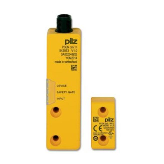
PSEN cs6.1 M12/8 Dimensions in mm Safety switch DEVICE SAFETY GATE INPUT 26,4 Actuator Legend: [1] Square marking [2] Triangle marking Operating Manual PSEN cs6.1 M12/8 1003423-EN-06... -
Page 33: Technical Details
Breaking capacity per output 2,4 W Potential isolation from system voltage Short circuit-proof Residual current at outputs 400 µA Voltage drop at OSSDs Conditional rated short circuit current 100 A Lowest operating current 2 mA Operating Manual PSEN cs6.1 M12/8 1003423-EN-06... - Page 34 10 - 55 Hz Amplitude 1 mm Shock stress In accordance with the standard EN 60947-5-2 Acceleration Duration 11 ms Airgap creepage Overvoltage category Pollution degree Rated insulation voltage 75 V Rated impulse withstand voltage 1 kV Operating Manual PSEN cs6.1 M12/8 1003423-EN-06...
- Page 35 Height 26,4 mm Width 101,6 mm Depth 19 mm Actuator dimensions Height 18 mm Width 37 mm Depth 19 mm Weight of safety switch 68 g Weight of actuator 15 g Weight 83 g Operating Manual PSEN cs6.1 M12/8 1003423-EN-06...
-
Page 36: Safety Characteristic Data
2) this product must accept any interference received, including interference that may cause undesired operation. Changes or modifications made to this product not expressly approved by Pilz may void the FCC authorization to operate this equipment. NOTE: This equipment has been tested and found to comply with the limits for a Class A digital device, pursuant to Part 15 of the FCC Rules. - Page 37 PSEN cs6.1 M12/8/ Safety gate system, fully 8-pin M12 male connector 542 109 PSEN cs6.1 M12 1unit coded PSEN cs6.1 M12/8 1switch Safety switch, fully coded 8-pin M12 male connector 542 159 PSEN cs6.1 M12 1actuator Actuator, coded 542 183 Accessories Installation materials...
- Page 38 Spring-loaded terminal 540 138 Device Diagnostics EC declaration of conformity This product/these products meet the requirements of the following directives of the European Parliament and of the Council. 2006/42/EC on machines 2014/53/EC on radio equipment Operating Manual PSEN cs6.1 M12/8 1003423-EN-06...
- Page 39 PSEN cs6.1 M12/8 The complete EC Declaration of Conformity is available on the Internet at www.pilz.com/ downloads. Representative: Norbert Fröhlich, Pilz GmbH & Co. KG, Felix-Wankel-Str. 2, 73760 Ost- fildern, Germany Operating Manual PSEN cs6.1 M12/8 1003423-EN-06...
- Page 40 Back cover Support Technical support is available from Pilz round the clock. Americas Australia Scandinavia Brazil +61 3 95600621 +45 74436332 +55 11 97569-2804 Spain Canada Europe +34 938497433 +1 888-315-PILZ (315-7459) Austria Switzerland Mexico +43 1 7986263-0 +41 62 88979-30...
Need help?
Do you have a question about the PSEN cs6.1 M12/8 and is the answer not in the manual?
Questions and answers