
Related Manuals for Broadcom Brocade DCX 8510-4 Backbone


Summary of Contents for Broadcom Brocade DCX 8510-4 Backbone
- Page 1 Brocade DCX 8510-4 Backbone Hardware Installation Guide Hardware Installation Guide 2 June 2020 Broadcom 53-1002177-19 2 June 2020...
- Page 2 2020 Broadcom. All Rights Reserved. Broadcom, the pulse logo, Brocade, the stylized B logo, Fabric OS, and SANnav are among the trademarks of Broadcom in the United States, the EU, and/or other countries. The term “Broadcom” refers to Broadcom Inc. and/or its subsidiaries.
-
Page 3: Table Of Contents
53-1002177-19 Hardware Installation Guide Brocade DCX 8510-4 Backbone Hardware Installation Guide Table of Contents About This Document..........................9 What’s new in this document............................9 Supported hardware and software..........................9 Notes, Cautions, and Danger Notices........................... 9 ® Contacting Technical Support for Your Brocade Product.................. - Page 4 53-1002177-19 Hardware Installation Guide Brocade DCX 8510-4 Backbone Hardware Installation Guide Time and Items Required............................35 Installing the Device in an 18–24-Inch Rack (XBR-DCX4S-0130)................35 Parts list................................35 Torque requirements............................37 Assembling the rack hardware.......................... 37 Installing the device in the rack.........................42 Installing the Device in a 27-31-Inch Rack (XBR-DCX4S-0121)................43...
- Page 5 53-1002177-19 Hardware Installation Guide Brocade DCX 8510-4 Backbone Hardware Installation Guide Setting the time zone..............................74 Synchronizing local time............................74 Determining installed software licenses........................75 Installing transceivers and attaching cables......................75 Installing SFP+ and mSFP transceivers and cables....................75 Qualified transceivers for the FC16-64 and CR16-x blades..................76 Installing QSFP transceivers and cables........................76...
- Page 6 53-1002177-19 Hardware Installation Guide Brocade DCX 8510-4 Backbone Hardware Installation Guide Removing a cable management finger assembly....................101 Replacing a cable management finger assembly....................101 Port and application blade removal and replacement..................... 101 Time and items required............................102 Removing a blade..............................102 Replacing a blade..............................
- Page 7 53-1002177-19 Hardware Installation Guide Brocade DCX 8510-4 Backbone Hardware Installation Guide Preparing for WWN card replacement........................128 Hot-swap replacement............................128 Power-down replacement............................129 Removing the WWN card and WWN bezel (logo plate)..................131 Transceiver and fiber optic cable removal and replacement.................. 134 Time and items required............................
- Page 8 53-1002177-19 Hardware Installation Guide Brocade DCX 8510-4 Backbone Hardware Installation Guide FC16-48 port blade port numbering...........................158 FC16-64 port blade port numbering...........................158 FS8-18 encryption blade port numbering........................159 FX8-24 extension blade port numbering........................159 Diagnostics and Troubleshooting....................160 Introduction................................... 160 Obtaining chassis and component status........................ 160 Interpreting POST and boot results...........................
-
Page 9: About This Document
DocSafe: You can download software and documentation. • Other Resources: Licensing Portal (top), SAN Health (top and bottom), Communities (top), Education (top). If you purchased Brocade product support from a Broadcom OEM/solution provider, contact your OEM/solution provider for all your product support needs. Broadcom 53-1002177-19... -
Page 10: Document Feedback
OEM/solution providers are trained and certified by Broadcom to support Brocade products. • Broadcom provides backline support for issues that cannot be resolved by the OEM/solution provider. • Brocade Supplemental Support augments your existing OEM support contract, providing direct access to Brocade expertise. -
Page 11: Product Overview
53-1002177-19 Hardware Installation Guide Brocade DCX 8510-4 Backbone Hardware Installation Guide Product Overview Product features Key product features include the following: • Up to 256 16-Gbps external ports in a single chassis , enabling high density SAN configurations with reduced footprint. - Page 12 53-1002177-19 Hardware Installation Guide Brocade DCX 8510-4 Backbone Hardware Installation Guide NOTE Device control processors and management modules contain batteries for RTC/NVRAM backup. Do not attempt to replace these batteries. Dispose of hardware components containing these batteries as required by local ordinances and regulations.
-
Page 13: Port Side View Of The Device
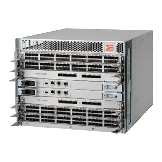
53-1002177-19 Hardware Installation Guide Brocade DCX 8510-4 Backbone Hardware Installation Guide Port side view of the device Figure 1: Port side view of the Brocade DCX 8510-4 (sample configuration) 1. Port blade (FC16-32) 2. Core switch blade (CR16-4) 3. Control processor blade (CP8) 4. -
Page 14: Nonport Side View Of The Device
53-1002177-19 Hardware Installation Guide Brocade DCX 8510-4 Backbone Hardware Installation Guide Figure 2: Port side view of Brocade DCX 8510-4 with the Airflow Diversion and Port Side Exhaust Kit installed (sample configuration) Nonport side view of the device The following figure shows a sample configuration of the nonport side view of the Brocade DCX 8510-4. -
Page 15: Supported Blades
53-1002177-19 Hardware Installation Guide Brocade DCX 8510-4 Backbone Hardware Installation Guide Figure 3: Nonport side view of the Brocade DCX 8510-4 (sample configuration) 1. WWN card bezel (logo plate) 2. Power supply 3. Blower assembly 4. Label with serial number and WWN... -
Page 16: Chassis Slots Numbering
53-1002177-19 Hardware Installation Guide Brocade DCX 8510-4 Backbone Hardware Installation Guide Table 1: Blades available for the device Description Name Function Control processor blade The CP8 blade contains the control plane for the chassis. There are two CP8 blades for redundancy. This control processor blade is compatible with the Brocade DCX 8510-8, Brocade DCX 8510-4, Brocade DCX-4S, and Brocade DCX platforms. -
Page 17: Port Numbering
53-1002177-19 Hardware Installation Guide Brocade DCX 8510-4 Backbone Hardware Installation Guide • Numbered 1 through 8, from bottom to top when facing the port side of the Brocade DCX 8510-4. • Slots 4 and 5 can be used only to install the control processor blades (CP8). -
Page 18: High Availability
53-1002177-19 Hardware Installation Guide Brocade DCX 8510-4 Backbone Hardware Installation Guide Blade Port numbering Trunking port groups • • FX8-24 blade FC ports labeled FC on the front panel: 0 through 11 Trunk group 0: FC ports 0-1 in two horizontal rows of six ports starting from the •... -
Page 19: Software Features
53-1002177-19 Hardware Installation Guide Brocade DCX 8510-4 Backbone Hardware Installation Guide • Modular design with hot-swappable components. • Flash memory that stores two firmware images per control processor. • USB port on control processor blades for most tasks that formerly required an FTP/SCP server, including software and firmware upgrades. -
Page 20: Network Manageability
53-1002177-19 Hardware Installation Guide Brocade DCX 8510-4 Backbone Hardware Installation Guide • DH-CHAP • SSHv2 (using AES, 3DES, RSA) • HTTPS (using AES) • SNMPv3 • FC-SP • Secure RPC • Secure file copy (SCP) • Telnet disable • Telnet timeout •... -
Page 21: Preparing For The Installation
Read the following sections before preparing to install the device. DANGER Use only optical transceivers that are qualified by Broadcom and comply with the FDA Class 1 radiation performance requirements defined in 21 CFR Subchapter I, and with IEC 60825 and EN60825. Optical products that do not comply with these standards might emit light that is hazardous to the eyes. -
Page 22: Time And Items Required
レーザ放射 光学器具で直接ビームを見ないこと クラス1 M レーザ製品 DANGER Use only optical transceivers that are qualified by Broadcom and comply with the FDA Class 1 radiation performance requirements defined in 21 CFR Subchapter I, and with IEC 60825 and EN60825. Optical products that do not comply with these standards might emit light that is hazardous to the eyes. -
Page 23: Items Included With The Device
53-1002177-19 Hardware Installation Guide Brocade DCX 8510-4 Backbone Hardware Installation Guide Table 3: Installation tasks, time, and items required Installation task Time estimate Items required Site preparation and unpacking the device 30 minutes 1/2-in. socket wrench (to remove pallet bolts). - Page 24 53-1002177-19 Hardware Installation Guide Brocade DCX 8510-4 Backbone Hardware Installation Guide – Control processor blades (CP8) – Core switch blades (CR16-4) – Port blades, application blades, and encryption blades (included based on customer specification) – Blade slot filler panels (for slots not filled by blades) –...
-
Page 25: Mounting The Device
53-1002177-19 Hardware Installation Guide Brocade DCX 8510-4 Backbone Hardware Installation Guide Mounting the Device Mounting options This device can be installed as a standalone unit on a flat surface or mounted a 19-inch Electronic Industries Association (EIA) or two-post telecommunications (TELCO)equipment rack. -
Page 26: Unpacking, Transporting, And Installing The Device
53-1002177-19 Hardware Installation Guide Brocade DCX 8510-4 Backbone Hardware Installation Guide DANGER Use safe lifting practices when moving the product. CAUTION To prevent damage to the chassis and components, never attempt to lift the chassis using the fan or power supply handles. -
Page 27: Installing The 8U Chassis Mid-Mount Rack Kit For Two-Post Racks (Xbr-Dcx4S-0126 And Xbr-X64-0126)
53-1002177-19 Hardware Installation Guide Brocade DCX 8510-4 Backbone Hardware Installation Guide 4. Remove the chassis door from the device. 5. Remove the vertical cable management fingers. 6. If installing the device in an equipment rack, install the applicable rack mount kit using instructions in Mounting the Device. - Page 28 53-1002177-19 Hardware Installation Guide Brocade DCX 8510-4 Backbone Hardware Installation Guide Figure 4: Rack Kit Parts (XBR-DCX4S-0126) 1. Saddle 2. Telco Mid-Mount Mounting Bracket (left) 3. Telco Mid-Mount Mounting Bracket (right) 4. 10-32 x .63 in.(1.60 cm) Phillips Screws with Square Cone Washer (for racks that have rails with round holes) 5.
- Page 29 53-1002177-19 Hardware Installation Guide Brocade DCX 8510-4 Backbone Hardware Installation Guide Figure 5: Rack Kit Parts (XBR-X64-0126) 1. Saddle 2. Telco Mid-Mount Mounting Bracket (left) 3. Telco Mid-mount Mounting Bracket (right) 4. 10-32 x .63 in.(1.60 cm) Phillips Screws with Square Cone Washer (for racks that have rails with round holes) 5.
-
Page 30: Assembling The Rack Hardware
53-1002177-19 Hardware Installation Guide Brocade DCX 8510-4 Backbone Hardware Installation Guide Assembling the Rack Hardware 1. Loosen the two 10-32 adjusting screws securing the each mid-mount bracket to the saddle (see the previous figure) and slide the brackets as far backward as possible. - Page 31 53-1002177-19 Hardware Installation Guide Brocade DCX 8510-4 Backbone Hardware Installation Guide Figure 7: Using Clip Nuts and Retainer Nuts to Secure Screws to Rack Rails 1. Clip Nuts (for rails with round holes) 2. Retainer Nuts (for rails with square holes) 3.
-
Page 32: Installing The Device In The Rack
53-1002177-19 Hardware Installation Guide Brocade DCX 8510-4 Backbone Hardware Installation Guide Figure 8: Telco Mid-Mount Brackets Installation 1. Telco Mid-Mount Mounting Brackets (left and right) Installing the device in the rack DANGER Use safe lifting practices when moving the product. - Page 33 53-1002177-19 Hardware Installation Guide Brocade DCX 8510-4 Backbone Hardware Installation Guide Figure 9: Sliding the device into the mid-mount saddle 6. Secure the device to the rack using six 10-32 screws with square-cone washers, three screws for each mounting bracket attached to the device. Refer to the following figure. Tighten the screws to 32 in-lb (36.86 cm-kg)
-
Page 34: Installing The 8U Chassis Airflow Diversion Or Port-Side Exhaust Kit For Four-Post Racks (Xbr-Dcx4S-0121 And Xbr-Dcx4S-0130)
53-1002177-19 Hardware Installation Guide Brocade DCX 8510-4 Backbone Hardware Installation Guide Figure 10: Device installed in mid-mount saddle 1. 10-32 screws with square-cone washers (6) NOTE For rails with round holes, use the clip nuts on the rack rails for securing 10-32 screws. For rails with square... -
Page 35: Time And Items Required
53-1002177-19 Hardware Installation Guide Brocade DCX 8510-4 Backbone Hardware Installation Guide For DCX-4S Directors, air flows into the device through its nonport side and out through the vent on the side of the chassis or air flows into the side vent and out the nonport side. This kit is designed to route the exhaust airflow fully to the port side of the chassis while mounted in a four-post rack. - Page 36 53-1002177-19 Hardware Installation Guide Brocade DCX 8510-4 Backbone Hardware Installation Guide Description Quantity Duct Shelf Shelf saddle 10-32 x .5 in. (1.27 cm) Phillips screw (blue Loctite on threads) 10-32 x .63 in.(1.60 cm) Phillips screw with square-cone washer 10-32 clip nut for racks that have rails with round holes...
-
Page 37: Torque Requirements
53-1002177-19 Hardware Installation Guide Brocade DCX 8510-4 Backbone Hardware Installation Guide 2. Duct 3. Shelf 4. 10-32 x .5 in. (1.27 cm) Phillips screw with blue Loctite on threads 5. 10-32 x .63 in.(1.60 cm) Phillips screw with square cone washer for racks that have rails with round holes 6. - Page 38 53-1002177-19 Hardware Installation Guide Brocade DCX 8510-4 Backbone Hardware Installation Guide these nuts in the rack rails to mount the shelf and device. You may mount the shelf and device in 9U of rack space higher or lower in the rack than shown.
- Page 39 53-1002177-19 Hardware Installation Guide Brocade DCX 8510-4 Backbone Hardware Installation Guide Figure 13: Installing saddle to equipment rack 1. Shelf saddle 2. 10-32 x .5 in. (1.27 cm) Phillips screw with blue Loctite on threads or 10-32 x .63 in.(1.60 cm) Phillips screw with square cone washer for racks that have rails with round holes.
- Page 40 53-1002177-19 Hardware Installation Guide Brocade DCX 8510-4 Backbone Hardware Installation Guide 4. Place the shelf (refer to the following figure) on the saddle then secure it to the rack rails using four 10-32 screws with washers (refer to Figure 7). Tighten the screws according to specifications under Torque requirements.
- Page 41 53-1002177-19 Hardware Installation Guide Brocade DCX 8510-4 Backbone Hardware Installation Guide 5. Install the air duct assembly (refer to the following figure) by inserting it down into the side-slot on the shelf. Ensure that the tabs of the duct align and engage with the slots in the shelf.
-
Page 42: Installing The Device In The Rack
53-1002177-19 Hardware Installation Guide Brocade DCX 8510-4 Backbone Hardware Installation Guide Figure 16: Securing top rail in rack 1. Top rail 2. Duct 3. 6-32 x .25 in. (.635 cm) Phillips screws 4. 10-32 x .5 in. (1.27 cm) Phillips screws with blue Loctite on threads and alignment washers or 10-32 x .63 in.(1.60 cm) Phillips screw with square cone washer... -
Page 43: Installing The Device In A 27-31-Inch Rack (Xbr-Dcx4S-0121)
53-1002177-19 Hardware Installation Guide Brocade DCX 8510-4 Backbone Hardware Installation Guide 3. If applicable, lock the wheels of the lift. 4. Carefully lift the device and slide it into the rack. 5. Secure the device to the rack with six 10-32 screws with washers, three screws on each side (refer to the following figure). -
Page 44: Parts List
53-1002177-19 Hardware Installation Guide Brocade DCX 8510-4 Backbone Hardware Installation Guide Parts list The following parts list refers to items illustrated in the following figure. NOTE Not all parts may be used with certain installations depending on the device type. -
Page 45: Torque Requirements
53-1002177-19 Hardware Installation Guide Brocade DCX 8510-4 Backbone Hardware Installation Guide Figure 18: Airflow Diversion and Port-Side Exhaust Kit assembly for 27-31 in. (68.58 to 78.74 cm) racks 1. Top rail 2. Duct 3. Shelf 4. 10-32 x .5 in. (1.27 cm) Phillips screw with blue Loctite on threads 5. -
Page 46: Assembling The Rack Hardware
53-1002177-19 Hardware Installation Guide Brocade DCX 8510-4 Backbone Hardware Installation Guide Table 7: Torque requirements for mounting screws Screw size Torque 6-32 x .25 in. (.635 cm) Phillips screw 8.75 in-lb (10 cm-kg) 10-32 x .63 in. (1.60 cm) Phillips screw 32 in-lb (36.86 cm-kg) - Page 47 53-1002177-19 Hardware Installation Guide Brocade DCX 8510-4 Backbone Hardware Installation Guide 3. Install the shelf as shown in the following figure. a) The shelf can be adjusted to a length of between 27 and 31 inches (68.58 and 78.74 cm) to accommodate your rack size.
- Page 48 53-1002177-19 Hardware Installation Guide Brocade DCX 8510-4 Backbone Hardware Installation Guide 2. Shelf 5. Install the top rail assembly to the air duct assembly as shown in the following figure. a) The top rail assembly can be adjusted to a length of between 27 and 31 inches (68.58 to 78.74 cm) to fit on the inside of the rack rails.
-
Page 49: Installing Shipping Brackets (Optional)
53-1002177-19 Hardware Installation Guide Brocade DCX 8510-4 Backbone Hardware Installation Guide 6. Secure the top rail assembly to the rack with four 10-32 screws, two screws on each end of the top rail assembly. • For rails with round holes, use two 10-32 screws with washers (refer to... -
Page 50: Installing The 8U Chassis 27-31-Inch Rail Rack Kit For Four-Post Racks (Xbr-Dcx4S-0120)
53-1002177-19 Hardware Installation Guide Brocade DCX 8510-4 Backbone Hardware Installation Guide Figure 23: Device and 27-31 in. (68.58 to 78.74 cm) kit installed in rack 1. Screw locations for 10-32 x .5 in. (1.27 cm) Phillips screw with blue Loctite on threads or 10-32 x .63 in.(1.60 cm) Phillips screw with square cone washer for racks that have rails with round holes. -
Page 51: Time And Items Required
53-1002177-19 Hardware Installation Guide Brocade DCX 8510-4 Backbone Hardware Installation Guide • Use Electronic Industries Association (EIA) standard racks to install a modular device in a 19 in. Provide a space that is 8 rack units (8U) high, with a rail-to-rail depth of 27-31 in.(68.58 to 78.74 cm). 1U is equal to 4.45 cm (1.75 in.). -
Page 52: Assembling The Rack Hardware
53-1002177-19 Hardware Installation Guide Brocade DCX 8510-4 Backbone Hardware Installation Guide Figure 24: Rack Kit Parts 1. Left Rail 2. Right Rail 3. 10-32 x .5 in. (1.27 cm) Phillips Screw 4. 10-32 x .63 in.(1.60 cm) Phillips Screw with Square Cone Washer (for racks that have rails with round holes) 5. - Page 53 53-1002177-19 Hardware Installation Guide Brocade DCX 8510-4 Backbone Hardware Installation Guide Figure 25: Device Rails Installed in Equipment Rack 1. 10-32 x .5 in. (1.27 cm) Phillips Screw (for square holes) or 10-32 x .63 in. (1.60 cm) Phillips Screw (for round holes) 3.
-
Page 54: Installing The Device In The Rack
53-1002177-19 Hardware Installation Guide Brocade DCX 8510-4 Backbone Hardware Installation Guide 2. Round Hole Rack Rail 3. Retainer Nut 4. Square Hole Rack Rail Installing the Device in the Rack 1. Ensure that the door is removed from the port side of the device if it is installed. See the procedures for removing and replacing the device door in this guide. - Page 55 53-1002177-19 Hardware Installation Guide Brocade DCX 8510-4 Backbone Hardware Installation Guide 6. Secure the device to the equipment rack racks with six 10-32 x .63 screws with square-cone washers, three screws on each side. Tighten the screws to a torque of 92 cm-kg (80 in-lb). See the following figure.
-
Page 56: Cable Management
53-1002177-19 Hardware Installation Guide Brocade DCX 8510-4 Backbone Hardware Installation Guide Cable Management Requirements and precautions The cable management finger assemblies are attached to the chassis on either side of the port side of the chassis and allow for simple cable management. The cable management finger assemblies can be installed without service disruption. -
Page 57: Installing Inter-Chassis Links (Icls)
53-1002177-19 Hardware Installation Guide Brocade DCX 8510-4 Backbone Hardware Installation Guide Figure 29: QSFP to QSFP standard cables 1. QSFP MTP connector Figure 30: QSFP-SFP/LC Break-out/Split-out cables 1. QSFP MTP connector 2. SFP+ LC connectors With the support for breakout cables, each port can be in a different mode. Inside the single physical QSFP port, individual ports can be configured as an E_Port, F_Port or EX_Port. - Page 58 53-1002177-19 Hardware Installation Guide Brocade DCX 8510-4 Backbone Hardware Installation Guide The following table describes the connector port LED patterns and the recommended actions for those patterns. Table 9: ICL QSFP connector port LEDs LED purpose Color Status Recommended action...
-
Page 59: Possible Icl Configurations
53-1002177-19 Hardware Installation Guide Brocade DCX 8510-4 Backbone Hardware Installation Guide Figure 32: 2 km QSFP with integrated cable 1. MTP 1x12 fiber male connector 2. Integrated 3 meter MTP cable 3. Transceiver with pull-tab • A third type of transceiver has a pull-tab to aid in removing the transceiver from the port connector (like shown in previous illustration), but has a separate MTP cable that plugs into the transceiver. - Page 60 53-1002177-19 Hardware Installation Guide Brocade DCX 8510-4 Backbone Hardware Installation Guide Figure 33: QSFP cable connections for Brocade DCX 8510 chassis (sample configuration) 1. Chassis 1 - DCX 8510-8 2. Chassis 2 - DCX 8510-4 The DCX 8510 chassis can be connected in a core/edge configuration. The following figure shows two core and four edge chassis.
- Page 61 53-1002177-19 Hardware Installation Guide Brocade DCX 8510-4 Backbone Hardware Installation Guide Figure 34: DCX 8510 core/edge ICL topology The DCX 8510 chassis can also be connected in a full mesh configuration as shown in the following figure. Although DCX 8510-8 chassis are shown in the figure, the chassis can be either DCX 8510-4 or DCX 8510-8. In this example, the trunk groups are shown in color.
-
Page 62: Using Brocade 2 Km Lwl Qsfps
53-1002177-19 Hardware Installation Guide Brocade DCX 8510-4 Backbone Hardware Installation Guide Figure 35: DCX 8510 full mesh ICL topology Using Brocade 2 km LWL QSFPs Up to 10 ICL ports using the 2km ICL QSFP are supported in a DCX 8510 backbone switch at the two km distance, which requires configuring 16 buffer credit per virtual channel. -
Page 63: Qualified Cables For The Fc8-64 Port Blade
53-1002177-19 Hardware Installation Guide Brocade DCX 8510-4 Backbone Hardware Installation Guide Figure 36: 2 km LWL QSFP transceiver with integrated cable 1. MTP 1 x 12 fiber male connector 2. Integrated 3 meter MTP cable 3. Transceiver with pull-tab Following are cabling options and recommendations: •... -
Page 64: High-Density Cabling For The Fc8-64 Port Blade
53-1002177-19 Hardware Installation Guide Brocade DCX 8510-4 Backbone Hardware Installation Guide Description Length Corning part number Molex part number Amphenol part number mSFP LC - standard LC, 10 m S50502S5120010M 106273-0529 943-99865-10010 duplex, multi-mode, OM3, 50/125 Patch cables - mSFP to... - Page 65 53-1002177-19 Hardware Installation Guide Brocade DCX 8510-4 Backbone Hardware Installation Guide Figure 38: Cable design for the mSFP patch cables for the FC8-64 high density port blade 1. mSFP connector 2. Duplex clip (black) 3. 6 mm cable 4. SFP connector Note that the duplex clip on the mSFP end of the cable is black for easier recognition.
-
Page 66: Initial Configuration
53-1002177-19 Hardware Installation Guide Brocade DCX 8510-4 Backbone Hardware Installation Guide Initial Configuration Items required The following items are required for initial setup and verification of the device: • The device, mounted and installed with the required blades, FRUs, transceivers, and cables and is connected to a power source. -
Page 67: Configuring The Device
53-1002177-19 Hardware Installation Guide Brocade DCX 8510-4 Backbone Hardware Installation Guide Configuring the device The device must be configured before it is connected to the fabric, and all of the configuration commands must be entered through the active CP blade. The device configuration includes the following parameters: •... -
Page 68: Establishing A Serial Connection To The Device
53-1002177-19 Hardware Installation Guide Brocade DCX 8510-4 Backbone Hardware Installation Guide Figure 39: Configuration tasks Establishing a serial connection to the device To establish a serial connection to the console port on the device, complete the following steps. 1. Verify that the device is powered on and that POST is complete by verifying that all power LED indicators on the port, control processor, and core switch blades display a steady green light. -
Page 69: Logging In To The Serial Console Port
53-1002177-19 Hardware Installation Guide Brocade DCX 8510-4 Backbone Hardware Installation Guide 3. Access the device using a terminal emulator application (such as HyperTerminal in a Windows environment or tip in a UNIX environment). 4. Disable any serial communication programs running on the workstation (such as synchronization programs). -
Page 70: Configuring The Ip Addresses
53-1002177-19 Hardware Installation Guide Brocade DCX 8510-4 Backbone Hardware Installation Guide Use Control-C to exit or press 'Enter' key to proceed. swDir:admin> 2. (Optional) Modify passwords. To skip modifying the password, press Ctrl+C. NOTE Passwords can be 8 to 40 characters long. They must begin with an alphabetic character. They can include numeric characters, the period (.), and the underscore (_) only. -
Page 71: Logging Off The Serial Console Port And Disconnecting The Serial Cable
53-1002177-19 Hardware Installation Guide Brocade DCX 8510-4 Backbone Hardware Installation Guide swDir:admin> ipaddrset -chassis Ethernet IP Address [0.0.0.0]: 192.168.1.1 Ethernet Subnetmask [0.0.0.0]: 255.255.255.0 Fibre Channel IP Address [0.0.0.0]: Fibre Channel Subnetmask [0.0.0.0]: Issuing gratuitous ARP...Done. Committing configuration...Done. swDir:admin> ipaddrset -cp 0 Host Name [cp0]: 192.168.1.2... -
Page 72: Establishing An Ethernet Connection To The Device
53-1002177-19 Hardware Installation Guide Brocade DCX 8510-4 Backbone Hardware Installation Guide Establishing an Ethernet connection to the device After using a serial connection to configure the IP addresses for the device, you can connect the active CP blade to the local area network (LAN). -
Page 73: Setting The Domain Id
53-1002177-19 Hardware Installation Guide Brocade DCX 8510-4 Backbone Hardware Installation Guide DCX8510_chassis 3. Record the new name for reference. Setting the domain ID Each switch in the fabric must have a unique domain ID. The domain ID can be manually set through the configure command or can be automatically set. -
Page 74: Setting The Time Zone
53-1002177-19 Hardware Installation Guide Brocade DCX 8510-4 Backbone Hardware Installation Guide switch:admin> date "0927123010" Thu Sep 27 12:30:00 UTC 2010 switch:admin> Setting the time zone You must perform the procedure on all chassis for which the time zone must be set. Because the value is written to nonvolatile memory, you only need to set the time zone once on each switch. -
Page 75: Determining Installed Software Licenses
53-1002177-19 Hardware Installation Guide Brocade DCX 8510-4 Backbone Hardware Installation Guide rest will be stored as backup servers that can take over if the active NTP server fails. The principal or primary FCS switch synchronizes its time with the NTP server every 64 seconds. -
Page 76: Qualified Transceivers For The Fc16-64 And Cr16-X Blades
53-1002177-19 Hardware Installation Guide Brocade DCX 8510-4 Backbone Hardware Installation Guide NOTE For current information on qualified transceivers supported by this device, refer to the Brocade Fibre Channel Transceiver Platform Support Matrix and Brocade Transceiver Module Resources on www.brocade.com NOTE The device supports only Brocade-qualified transceivers. - Page 77 53-1002177-19 Hardware Installation Guide Brocade DCX 8510-4 Backbone Hardware Installation Guide transceivers should be installed in the blades before connecting the cables. As each QSFP contains four 16-Gbps ports, be aware that any problems with one port could affect all four ports in the quad if the QSFP must be replaced.
-
Page 78: Managing Cables
53-1002177-19 Hardware Installation Guide Brocade DCX 8510-4 Backbone Hardware Installation Guide ------ No_Module ------ No_Module ------ No_Module ------ No_Module ------ No_Module ------ No_Module ------ No_Module ------ No_Module ------ No_Module ------ No_Module ------ No_Module ------ No_Module ------ No_Module ------ No_Module ------... -
Page 79: Verifying Correct Operation And Backing Up The Configuration
53-1002177-19 Hardware Installation Guide Brocade DCX 8510-4 Backbone Hardware Installation Guide • Leave at least 1 m (3.28 ft) of slack for each port cable. This provides room to remove and replace the device, allows for inadvertent movement of the rack, and helps prevent the cables from being bent to less than the minimum bend radius. -
Page 80: Powering Off The Chassis
53-1002177-19 Hardware Installation Guide Brocade DCX 8510-4 Backbone Hardware Installation Guide Powering off the chassis Perform the following steps to power off the chassis. 1. Shut down the chassis using the command. sysShutdown switch::admin> sysshutdown This command will shutdown the operating systems on your switch. -
Page 81: System Monitoring
53-1002177-19 Hardware Installation Guide Brocade DCX 8510-4 Backbone Hardware Installation Guide System Monitoring Monitoring overview The Brocade DCX 8510-4 is engineered for reliability and requires no routine operational steps or maintenance. This chapter provides information about determining the status of each component using LEDs and CLI commands. Refer to the Brocade Web Tools Administration Guide and the Brocade Fabric OS Administration Guide for additional information. - Page 82 53-1002177-19 Hardware Installation Guide Brocade DCX 8510-4 Backbone Hardware Installation Guide 821500 Online F-Port 10:00:00:05:33:26:10:72 821600 Online F-Port 10:00:00:05:33:48:5e:f4 821700 Online F-Port 10:00:00:05:1e:f8:a0:b2 821800 No_Module 821900 No_Module 821a00 No_Module 821b00 No_Module 821c00 No_Light 821d00 No_Light 821e00 No_Light 821f00 No_Light 822000...
- Page 83 53-1002177-19 Hardware Installation Guide Brocade DCX 8510-4 Backbone Hardware Installation Guide Manufacture: Day: 19 Month: 11 Year: 2010 Update: Day: 29 Month: Year: 2011 Time Alive: 32 days Time Awake: 0 days CP BLADE Slot: 4 Header Version: Power Consume Factor:...
- Page 84 53-1002177-19 Hardware Installation Guide Brocade DCX 8510-4 Backbone Hardware Installation Guide Power Consume Factor: -140 Power Usage (Watts): Factory Part Num: 60-1002145-02 Factory Serial Num: BQA0344F00S Manufacture: Day: Month: 11 Year: 2010 Update: Day: 29 Month: Year: 2011 Time Alive:...
-
Page 85: Determining The Status Of A Port, Application, Or Extension Blade
53-1002177-19 Hardware Installation Guide Brocade DCX 8510-4 Backbone Hardware Installation Guide BRD0000CA Part Num: SLKWRM0000X4S Unit: 2 Header Version: Power Consume Factor: Factory Part Num: 60-1000888-05 Factory Serial Num: ANQ0417F03P Manufacture: Day: Month: Year: 2010 Update: Day: 29 Month: Year: 2011... -
Page 86: Fc8-48E Port Blade Leds
53-1002177-19 Hardware Installation Guide Brocade DCX 8510-4 Backbone Hardware Installation Guide FC8-48E port blade LEDs Figure 41: FC8-48E port blade LEDs 1. Blade status LED 2. Blade power LED 3. Fibre Channel port 4. Port status LED FC8-64 port blade LEDs Figure 42: FC8-64 port blade LEDs 1. -
Page 87: Fc16-32 Port Blade Leds
53-1002177-19 Hardware Installation Guide Brocade DCX 8510-4 Backbone Hardware Installation Guide FC16-32 port blade LEDs Figure 43: FC16-32 port blade LEDs 1. Blade status LED 2. Blade power LED 3. Fibre Channel port 4. Port status LED FC16-48 port blade LEDs Figure 44: FC16-48 port blade LEDs 1. -
Page 88: Fc16-64 Port Blade Leds
53-1002177-19 Hardware Installation Guide Brocade DCX 8510-4 Backbone Hardware Installation Guide FC16-64 port blade LEDs Figure 45: FC16-64 port blade LEDs 1. Blade status LED 2. Blade power LED 3. Port status LED for FC port 36 4. QSFP port 9; FC ports 36-39 (right to left) -
Page 89: Fx8-24 Extension Blade Leds
53-1002177-19 Hardware Installation Guide Brocade DCX 8510-4 Backbone Hardware Installation Guide FX8-24 extension blade LEDs Figure 47: FX8-24 extension blade LEDs 1. Blade status LED 2. Blade power LED 3. GbE (GE) port 6 4. Port status LED for GbE port 6 5. -
Page 90: Fc Ports Status Led Description
53-1002177-19 Hardware Installation Guide Brocade DCX 8510-4 Backbone Hardware Installation Guide Table 13: Port and application blades status LED description LED purpose Color Status Recommended action Status LED No light (LED is off) Blade is either healthy or does Verify that the power LED is on. -
Page 91: Gbe And 10-Gbe Ports Status Led Description
53-1002177-19 Hardware Installation Guide Brocade DCX 8510-4 Backbone Hardware Installation Guide LED purpose Color Status Recommended action Slow-flashing amber (on 2 Port is disabled due Reset the port from seconds, then off 2 seconds) to diagnostic tests the workstation using... -
Page 92: Determining The Status Of A Control Processor Blade (Cp8)
53-1002177-19 Hardware Installation Guide Brocade DCX 8510-4 Backbone Hardware Installation Guide Determining the status of a control processor blade (CP8) Complete the following steps to determine the status of a control processor blade (CP8) 1. Check the LED indicators on the CP blade. The LED patterns may temporarily change during POST and other diagnostic tests. -
Page 93: Determining The Status Of A Core Switch Blade (Cr16-4)
53-1002177-19 Hardware Installation Guide Brocade DCX 8510-4 Backbone Hardware Installation Guide LED purpose Color Status Recommended action Fast-flashing amber (on 1/2 Environmental range exceeded. Check for out-of-bounds second, then off 1/2 second) environmental condition and correct it. Ethernet Link Status... -
Page 94: Determining The Status Of A Power Supply
53-1002177-19 Hardware Installation Guide Brocade DCX 8510-4 Backbone Hardware Installation Guide Table 17: CR blade LED descriptions LED purpose Color Status Recommended action Power Steady green CR16-4 blade is on. No action required. No light (LED is off) CR16-4 blade is not on. -
Page 95: Determining The Status Of A Blower Assembly
53-1002177-19 Hardware Installation Guide Brocade DCX 8510-4 Backbone Hardware Installation Guide Figure 50: Power supply 1. Power LED The following table describes the power supply LED patterns and the recommended actions for those patterns. Table 18: Power supply LED descriptions... -
Page 96: Determining The Status Of A Wwn Card
53-1002177-19 Hardware Installation Guide Brocade DCX 8510-4 Backbone Hardware Installation Guide Figure 51: Blower assembly 1. Power LED 2. Fault LED The following table describes the LED patterns for the blower assembly. Table 19: Blower assembly LED descriptions LED purpose... - Page 97 53-1002177-19 Hardware Installation Guide Brocade DCX 8510-4 Backbone Hardware Installation Guide Enter the command to display information about the WWN card. (WWN units correspond to information chassisShow specific to the WWN card.) Error messages that may indicate problems with a WWN card are summarized in the following table.
- Page 98 53-1002177-19 Hardware Installation Guide Brocade DCX 8510-4 Backbone Hardware Installation Guide Type of message Sample error message <timestamp>, [EM-1049], <sequence-number>,, WWN unit insertion was detected. INFO, <system-name>, FRU WWN # insertion detected. <timestamp>, [EM-1050], <sequence-number>,, WWN unit removal was detected.
-
Page 99: Removal And Replacement Procedures
53-1002177-19 Hardware Installation Guide Brocade DCX 8510-4 Backbone Hardware Installation Guide Removal and Replacement Procedures Introduction NOTE Read the safety notices before servicing (Caution and Danger Notices). The field-replaceable units (FRUs) in the device can be removed and replaced without special tools. The device can continue operating during many of the FRU replacements if the conditions specified in the procedures are followed. -
Page 100: Replacing A Chassis Door
53-1002177-19 Hardware Installation Guide Brocade DCX 8510-4 Backbone Hardware Installation Guide Figure 53: Removal and replacement of the chassis door Replacing a chassis door Complete the following steps to reinstall the door. 1. Align the holes in the door with the ball studs on the chassis. -
Page 101: Removing A Cable Management Finger Assembly
53-1002177-19 Hardware Installation Guide Brocade DCX 8510-4 Backbone Hardware Installation Guide Removing a cable management finger assembly Complete the following steps to remove the cable management finger assembly. 1. Remove the chassis door. 2. Remove the cables from the cable management finger assembly and rearrange the cables around the assembly. -
Page 102: Time And Items Required
53-1002177-19 Hardware Installation Guide Brocade DCX 8510-4 Backbone Hardware Installation Guide CAUTION If you do not install a module or a power supply in a slot, you must keep the slot filler panel in place. If you run the chassis with an uncovered slot, the system will overheat. - Page 103 53-1002177-19 Hardware Installation Guide Brocade DCX 8510-4 Backbone Hardware Installation Guide NOTE Before removing any cables from a blade, note the cable order (identify each cable by its physical port). It is a good practice to keep a table of cable to port mapping.
-
Page 104: Replacing A Blade
53-1002177-19 Hardware Installation Guide Brocade DCX 8510-4 Backbone Hardware Installation Guide 10. Unscrew the two thumbscrews from the ejectors on the blade using the Phillips screwdriver. Unscrew the left thumbscrew until it pops out. This initiates a hot-swap request. 11. Wait for the power LED to turn off in response to the hot-swap request before removing the blade. -
Page 105: Blade Filler Panel Removal And Replacement
53-1002177-19 Hardware Installation Guide Brocade DCX 8510-4 Backbone Hardware Installation Guide DANGER For safety reasons, the ESD wrist strap should contain a series 1 megaohm resistor. 1. Orient the blade so that the ports are at the front of the chassis and the flat side of the blade is on the bottom. -
Page 106: Replacing A Filler Panel
53-1002177-19 Hardware Installation Guide Brocade DCX 8510-4 Backbone Hardware Installation Guide CAUTION If you do not install a module or a power supply in a slot, you must keep the slot filler panel in place. If you run the chassis with an uncovered slot, the system will overheat. -
Page 107: Time And Items Required
53-1002177-19 Hardware Installation Guide Brocade DCX 8510-4 Backbone Hardware Installation Guide the directions under Downloading firmware from an FTP server Downloading firmware from a USB device carefully. NOTE If the new CP blade does not have the same firmware as the active CP blade, the new blade must be upgraded to the same firmware version. - Page 108 53-1002177-19 Hardware Installation Guide Brocade DCX 8510-4 Backbone Hardware Installation Guide NOTE The following instructions reference specific slot numbers as examples. These numbers will be different on a chassis with slots for four port blades and a chassis with slots for eight port blades. These numbers will be different between the DCX 8510-8/DCX and the DCX 8510-4/DCX-4S chassis.
-
Page 109: Power-Up Procedure
53-1002177-19 Hardware Installation Guide Brocade DCX 8510-4 Backbone Hardware Installation Guide 8. Run from the active CP blade to prevent failover or communication between the CP blades during the haDisable replacement. 9. Enter the command. This command uploads the backbone virtual fabric data. -
Page 110: Replacing A Control Processor Blade (Cp8)
53-1002177-19 Hardware Installation Guide Brocade DCX 8510-4 Backbone Hardware Installation Guide 4. Enter the command. This is required before physically removing and replacing a CP blade. haDisable 5. Power off the blade by sliding the slider switch in the left ejector to the right to the off position. Do not eject the blade until the power LED is off and you have completed the next two steps. -
Page 111: Power-Down Procedure
53-1002177-19 Hardware Installation Guide Brocade DCX 8510-4 Backbone Hardware Installation Guide Complete the following steps to remove a CP8 control blade. 1. Open the ejector handles to approximately 45 degrees. Orient the CP blade so that the handles are toward you and the flat metal side should be facing down. -
Page 112: Verifying Operation Of The New Cp Blade
53-1002177-19 Hardware Installation Guide Brocade DCX 8510-4 Backbone Hardware Installation Guide 5. Power down the chassis. 6. Remove CP blades using the following steps: a) Disconnect all cables from the blades. b) Unscrew the thumbscrew from both ejectors for a blade using the Phillips screwdriver. -
Page 113: Downloading Firmware From An Ftp Server
53-1002177-19 Hardware Installation Guide Brocade DCX 8510-4 Backbone Hardware Installation Guide 2. Log into each CP blade and enter the command to display the CP status. Verify the CP state, status, health, haShow and that the HA state is synchronized. Remedy any issues before proceeding. For more information on... - Page 114 53-1002177-19 Hardware Installation Guide Brocade DCX 8510-4 Backbone Hardware Installation Guide Complete the following steps to download the firmware from an FTP server. 1. Log in to the standby CP blade as admin. If you need to know the IP address of the standby blade, run ipaddrshow You should remain logged in to the active CP blade in order to monitor it.
-
Page 115: Downloading Firmware From A Usb Device
53-1002177-19 Hardware Installation Guide Brocade DCX 8510-4 Backbone Hardware Installation Guide 5. Log back in to the standby CP blade and run on the standby CP blade to validate a firmwareDownloadStatus successful commit. This may take 10 minutes. 6. If you are upgrading through several levels of the Fabric OS, repeat step 2 through step 5 as often as necessary based on the path outlined in the preceding table. - Page 116 53-1002177-19 Hardware Installation Guide Brocade DCX 8510-4 Backbone Hardware Installation Guide INIT: Switching to runlevel: 6 INIT: Sending processes the TERM signal DCX_124:admin> HAMu Heartbeat down, stop FSS Unmounting all ##exiting due to signal: 9, pending signals: 0x20000, 0x0 ilesystems.
- Page 117 53-1002177-19 Hardware Installation Guide Brocade DCX 8510-4 Backbone Hardware Installation Guide Slot 1 (CP0, active): Firmwaredownload command has completed successfully. Use firmwareshow to verify the firmware versions. 4. On the standby CP blade (the blade for which you just changed the firmware level), run reboot . The reboot of the standby CP will initiate a firmwarecommit to the secondary partition and log you out.
- Page 118 53-1002177-19 Hardware Installation Guide Brocade DCX 8510-4 Backbone Hardware Installation Guide Complete the following steps to download the firmware from a USB device to the replacement blade. 1. Insert the USB device into the active CP blade. 2. Attach a serial cable from the PC to the active CP blade.
-
Page 119: Completing The Replacement
53-1002177-19 Hardware Installation Guide Brocade DCX 8510-4 Backbone Hardware Installation Guide 8. Log back on to the standby CP blade and enter firmwareDownloadStatus on the standby CP blade to validate a successful commit. This may take 10 minutes. 9. If you are upgrading through several levels of the Fabric OS, repeat step 5 through step 8 as often as necessary based on the path outlined in the preceding table. -
Page 120: Core Switch Blade (Cr16-X) Removal And Replacement
53-1002177-19 Hardware Installation Guide Brocade DCX 8510-4 Backbone Hardware Installation Guide 4. Pack the faulty CP blade in the packaging provided with the new CP blade, and contact the switch supplier to determine the return procedure. 5. Replace the chassis door. -
Page 121: Replacing A Core Switch Blade (Cr16-X)
53-1002177-19 Hardware Installation Guide Brocade DCX 8510-4 Backbone Hardware Installation Guide NOTE The CR16-4 blade is compatible only with the Brocade DCX 8510-4. NOTE The device continues to operate while a core switch blade is being replaced. Complete the following steps to remove the core switch blade. -
Page 122: Power Supply Removal And Replacement
53-1002177-19 Hardware Installation Guide Brocade DCX 8510-4 Backbone Hardware Installation Guide Complete the following steps to replace the core switch blade. 1. Open the ejectors by rotating them toward the center of the blade face. Orient the CR blade so that the handles are toward you. -
Page 123: Removing A Power Supply
53-1002177-19 Hardware Installation Guide Brocade DCX 8510-4 Backbone Hardware Installation Guide Figure 59: Power supply identification 1. Power supply 1 (PS1) 2. Power supply 2 (PS2) Removing a power supply To remove a power supply, complete the following steps. 1. Perform the appropriate following action based on whether the device is operating: •... -
Page 124: Replacing A Power Supply
53-1002177-19 Hardware Installation Guide Brocade DCX 8510-4 Backbone Hardware Installation Guide Replacing a power supply To replace a power supply, complete the following steps. 1. If you are not replacing the power supply, insert a filler panel into the slot. -
Page 125: Removing A Blower Assembly
53-1002177-19 Hardware Installation Guide Brocade DCX 8510-4 Backbone Hardware Installation Guide Removing a blower assembly Complete the following steps to remove a blower assembly from the chassis. 1. Before removing a blower assembly, verify that the other blower assemblies are functioning correctly. The power LEDs should be steady green. -
Page 126: Time And Items Required
53-1002177-19 Hardware Installation Guide Brocade DCX 8510-4 Backbone Hardware Installation Guide RASlog messages and use the WWN Recovery Tool ( ) as directed in the following sections to recover WWN wwnrecover cards. The tool will direct you to contact customer support if recovery fails. In these cases, Brocade Support will determine whether one or both WWN cards need replaced and will request the partner or OEM to send WWN cards from FRU inventory to the nearest Brocade Support office to be reprogrammed. -
Page 127: Verifying The Need For Replacement
53-1002177-19 Hardware Installation Guide Brocade DCX 8510-4 Backbone Hardware Installation Guide If a data mismatch is detected during the audit, messages in the RASlog will provide a summary of all errors detected and prompt you through a data recovery process. The data recovery mechanism may vary depending on the error encountered and the data being compared. -
Page 128: Preparing For Wwn Card Replacement
53-1002177-19 Hardware Installation Guide Brocade DCX 8510-4 Backbone Hardware Installation Guide Preparing for WWN card replacement If the WWN cards require replacement, complete the following steps. Follow electrostatic discharge (ESD) precautions. DANGER For safety reasons, the ESD wrist strap should contain a series 1 megaohm resistor. -
Page 129: Power-Down Replacement
53-1002177-19 Hardware Installation Guide Brocade DCX 8510-4 Backbone Hardware Installation Guide 4. Verify that the WWN card is correctly connected by noting if the LEDs on the card reflects the status of the components. 5. Address any issues flagged by any RASlog EM-1220 and EM-1222 messages that display for the new card before proceeding. - Page 130 53-1002177-19 Hardware Installation Guide Brocade DCX 8510-4 Backbone Hardware Installation Guide DANGER For safety reasons, the ESD wrist strap should contain a series 1 megaohm resistor. NOTE Be aware that if replacing both WWN cards, the IP addresses on the new WWN cards will be in effect when the chassis powers up.
-
Page 131: Removing The Wwn Card And Wwn Bezel (Logo Plate)
53-1002177-19 Hardware Installation Guide Brocade DCX 8510-4 Backbone Hardware Installation Guide 8. Determine the active CP by entering the command. haShow 9. On the active CP, run the command and specify WWN 2 card for recovery when prompted in wwnrecover wwnrecover output messages. - Page 132 53-1002177-19 Hardware Installation Guide Brocade DCX 8510-4 Backbone Hardware Installation Guide (FICON/mainframe environments only) ficonshow switchrnid configupload The factory serial number and the sequence number in the following outputs should match, except in the ficonshow , which will have a number appended to the front indicating that the logical switch number, if virtual fabrics...
- Page 133 53-1002177-19 Hardware Installation Guide Brocade DCX 8510-4 Backbone Hardware Installation Guide If there are other logical switches on your chassis, use the command to connect to all the other setcontext switches and then run on these switches as well. switchcfgpersistentdisable b) Power down the entire chassis.
-
Page 134: Transceiver And Fiber Optic Cable Removal And Replacement
53-1002177-19 Hardware Installation Guide Brocade DCX 8510-4 Backbone Hardware Installation Guide Figure 63: Removal and replacement of the WWN bezel (logo plate) and WWN card 7. Use a Phillips screwdriver to unscrew the screws that secure the WWN card to the chassis. -
Page 135: Time And Items Required
53-1002177-19 Hardware Installation Guide Brocade DCX 8510-4 Backbone Hardware Installation Guide Time and items required The replacement procedure for a transceiver takes less than five minutes. Items required The following items are needed to replace a transceiver: • Replacement mSFP, SFP, SFP+, or XFP •... -
Page 136: Replacing An Sfp+ Transceiver
53-1002177-19 Hardware Installation Guide Brocade DCX 8510-4 Backbone Hardware Installation Guide Figure 65: Replacing an optical transceiver 1. Bail Figure 66: Replacing a 16 Gbps SFP+ optical transceiver Replacing an SFP+ transceiver Complete the following steps to replace an SFP+ transceiver. -
Page 137: Removing And Replacing An Msfp Optical Transceiver And Cable
53-1002177-19 Hardware Installation Guide Brocade DCX 8510-4 Backbone Hardware Installation Guide Removing and replacing an mSFP optical transceiver and cable Use the procedures in this section to remove and replace mSFP transceivers. Follow these guidelines while removing and replacing mSFP transceivers. -
Page 138: Qualified Transceivers For The Fc16-64 And Cr16-X Blades
53-1002177-19 Hardware Installation Guide Brocade DCX 8510-4 Backbone Hardware Installation Guide • The QSFP transceivers are used only with the FC16-64 port blades and core switch blades. Refer to "Qualified transceivers for the FC16-64 and CR16-x blades" in this publication for a list of QSFPs qualified for these blades. -
Page 139: Replacing A Qsfp Transceiver And Cable
53-1002177-19 Hardware Installation Guide Brocade DCX 8510-4 Backbone Hardware Installation Guide Figure 69: 2 km LWL QSFP transceiver with pull-tab and integrated cable 1. MTP 1x12 fiber male connector 2. Integrated 3 meter MTP cable 3. Transceiver with pull-tab •... -
Page 140: Chassis Removal And Replacement
53-1002177-19 Hardware Installation Guide Brocade DCX 8510-4 Backbone Hardware Installation Guide c) Repeat for each cable that requires replacement. d) Once all the cables are attached, refer to the Brocade Fabric OS Administration Guide for the configuration procedure. 2. If replacing a transceiver that has an integrated cable and pull-tab, perform the following steps: a) Align the transceiver with the blade port. -
Page 141: Faulty Chassis Indicators
53-1002177-19 Hardware Installation Guide Brocade DCX 8510-4 Backbone Hardware Installation Guide Faulty chassis indicators Verify that replacement of the chassis is necessary. Ensure that the components are firmly seated when troubleshooting, and contact your support provider with any questions about whether the chassis should be replaced. - Page 142 53-1002177-19 Hardware Installation Guide Brocade DCX 8510-4 Backbone Hardware Installation Guide Checked? Data Notes Information about the new chassis New factory serial number New serial number (if available) 1. Open a Telnet session and log in to the device as admin. The default password is password. Enable the logging function on your Telnet or serial console connection.
- Page 143 53-1002177-19 Hardware Installation Guide Brocade DCX 8510-4 Backbone Hardware Installation Guide Backplane IP address of CP1 : 10.0.0.6 IPv6 Autoconfiguration Enabled: Yes Local IPv6 Addresses: chassis 0 stateless fd00:60:69bc:63:205:1eff:fe39:e45a/64 preferred chassis 0 stateless fec0:60:69bc:63:205:1eff:fe39:e45a/64 preferred cp 0 stateless fd00:60:69bc:63:205:1eff:fe40:6230/64 preferred...
- Page 144 53-1002177-19 Hardware Installation Guide Brocade DCX 8510-4 Backbone Hardware Installation Guide Copy the command output into a text file named "SANbefor.txt." After the device is restored to the fabric, this information can be used to verify that no unintentional changes have occurred to the fabric.
-
Page 145: Disconnecting From Network And Fabric
53-1002177-19 Hardware Installation Guide Brocade DCX 8510-4 Backbone Hardware Installation Guide 9. Record the cable connections between the chassis and the target device and ports. 10. Run on the active CP. The information recorded can be very important in case you have difficulties supportSave during the replacement process. -
Page 146: Installing The Replacement Chassis
53-1002177-19 Hardware Installation Guide Brocade DCX 8510-4 Backbone Hardware Installation Guide DANGER For safety reasons, the ESD wrist strap should contain a series 1 megaohm resistor. 1. Remove the chassis door (Chassis door removal and replacement) if not already done. -
Page 147: Downloading The Configuration
53-1002177-19 Hardware Installation Guide Brocade DCX 8510-4 Backbone Hardware Installation Guide NOTE New WWN cards are shipped preinstalled in the replacement chassis. Do not replace the WWN cards in the replacement chassis with the old WWN cards from chassis that you are replacing. This will result in licensing and return materials authorization (RMA) issues for your product. -
Page 148: Reconnecting The System To The Network And Fabric
53-1002177-19 Hardware Installation Guide Brocade DCX 8510-4 Backbone Hardware Installation Guide switch:admin> login login: admin password: xxxxxxxx switch:admin> NOTE If you are using the Virtual Fabric feature, you must run before running the configdownload -vf command to restore the logical switch configuration. -
Page 149: Verifying Correct Operation Of System
53-1002177-19 Hardware Installation Guide Brocade DCX 8510-4 Backbone Hardware Installation Guide Verifying correct operation of system Complete the following steps to verify the correct operation of the device. 1. Log in to the device as admin. switch:admin> login login: admin password: xxxxxxxx switch:admin>... -
Page 150: Verifying Correct Configuration Of The Fabric
53-1002177-19 Hardware Installation Guide Brocade DCX 8510-4 Backbone Hardware Installation Guide 4. Verify that all the IP address information is correct by entering and checking the results against the IP ipAddrShow information recorded in the config-miscinfo.txt file. switch:admin> ipaddrshow SWITCH Ethernet IP Address: xxx.xxx.xxx.12... -
Page 151: Cable Routing Table
53-1002177-19 Hardware Installation Guide Brocade DCX 8510-4 Backbone Hardware Installation Guide Port ------------------------------------------------------------------- 1 | 1 | 1 | 1 | 1 | 128 | 128 | 128 | 128 | 128 | <output truncated> switch:admin> 2. Determine any differences between the information in the SANafter.txt file and the information in the SANbefor.txt file created earlier. - Page 152 53-1002177-19 Hardware Installation Guide Brocade DCX 8510-4 Backbone Hardware Installation Guide Slot/port Cable labels Connected device Slot/port of device Broadcom 53-1002177-19...
- Page 153 53-1002177-19 Hardware Installation Guide Brocade DCX 8510-4 Backbone Hardware Installation Guide Slot/port Cable labels Connected device Slot/port of device Broadcom 53-1002177-19...
-
Page 154: Application And Encryption Blades
53-1002177-19 Hardware Installation Guide Brocade DCX 8510-4 Backbone Hardware Installation Guide Application and Encryption Blades Introduction This appendix provides details about the application and encryption blades that are available optionally for the device. Contact your device supplier for additional information. - Page 155 53-1002177-19 Hardware Installation Guide Brocade DCX 8510-4 Backbone Hardware Installation Guide • 12 autosensing FC ports with link speeds of 1, 2, 4, or 8 Gbps • Ten GbE ports supporting FCIP with fixed link speed at 1 Gbps •...
-
Page 156: Port Numbering Templates
53-1002177-19 Hardware Installation Guide Brocade DCX 8510-4 Backbone Hardware Installation Guide Port Numbering Templates CR16-4 core blade port numbering Figure 70: CR16-4 core blade port numbering 1. Port map 2. QSFP ports 4-7 (right to left) 3. QSFP ports 0-3 (right to left) -
Page 157: Fc8-48E Port Blade Port Numbering
53-1002177-19 Hardware Installation Guide Brocade DCX 8510-4 Backbone Hardware Installation Guide 4. Port and trunking group map 5. FC ports 16-23 (right to left) 6. FC ports 0-7 (right to left) 7. FC ports 8-15 (right to left) FC8-48E port blade port numbering Figure 72: FC8-48E port blade port numbering 1. -
Page 158: Fc16-32 Port Blade Port Numbering
53-1002177-19 Hardware Installation Guide Brocade DCX 8510-4 Backbone Hardware Installation Guide FC16-32 port blade port numbering Figure 74: FC16-32 port blade port numbering 1. Blade power LED 2. Blade status LED 3. FC ports 24-31 (right to left) 4. Port and trunking group map 5. -
Page 159: Fs8-18 Encryption Blade Port Numbering
53-1002177-19 Hardware Installation Guide Brocade DCX 8510-4 Backbone Hardware Installation Guide 2. QSFP ports 0-7; FC ports 0-31 (right to left) FS8-18 encryption blade port numbering Figure 77: FS8-18 encryption blade port numbering 1. Gigabit Ethernet ports GE0-GE1 2. Smart card port 3. -
Page 160: Diagnostics And Troubleshooting
53-1002177-19 Hardware Installation Guide Brocade DCX 8510-4 Backbone Hardware Installation Guide Diagnostics and Troubleshooting Introduction For information about troubleshooting the entire fabric, refer to the Fabric OS Troubleshooting and Diagnostics Guide. The device includes a number of diagnostic aids to assist with troubleshooting, including LEDs on the hardware, commands that display current status, diagnostic tests for hardware and software, and error messages. -
Page 161: Interpreting Post And Boot Results
53-1002177-19 Hardware Installation Guide Brocade DCX 8510-4 Backbone Hardware Installation Guide Interpreting POST and boot results The device performs Power-On Self-Test (POST) by default each time the chassis is powered on, rebooted, or reset. The device can be rebooted using the (to reboot each CP individually) or commands. -
Page 162: Troubleshooting
53-1002177-19 Hardware Installation Guide Brocade DCX 8510-4 Backbone Hardware Installation Guide NOTE Error messages do not necessarily indicate that the device requires maintenance. Each diagnostic test can be implemented by entering the related command through a Telnet or serial session. For a list of diagnostic tests and commands, refer to the Brocade Fabric OS Administration Guide. - Page 163 53-1002177-19 Hardware Installation Guide Brocade DCX 8510-4 Backbone Hardware Installation Guide Issue Possible cause Recommended action The device was rebooted while an WWN card was uninstalled or failed. Initial setup results in IP address/Domain ID The device was connected to the fabric Refer to the Brocade Fabric OS conflict.
- Page 164 53-1002177-19 Hardware Installation Guide Brocade DCX 8510-4 Backbone Hardware Installation Guide Issue Possible cause Recommended action Blades might be faulty. Enter the slotShow command to determine status. For more information, enter the diagDisablePost command; then, use the slotPowerOff [slot number] and slotPowerOn [slot number[ command.
-
Page 165: Regulatory Statements
53-1002177-19 Hardware Installation Guide Brocade DCX 8510-4 Backbone Hardware Installation Guide Regulatory Statements BSMI Statement (Taiwan) Warning: This is Class A product. In a domestic environment, this product may cause radio interference, in which case the user may be required to take adequate measures. -
Page 166: China Rohs
53-1002177-19 Hardware Installation Guide Brocade DCX 8510-4 Backbone Hardware Installation Guide China ROHS FCC Warning (U.S. Only) This equipment has been tested and complies with the limits for a Class A computing device pursuant to Part 15 of the FCC rules. These limits are designed to provide reasonable protection against harmful interference when the equipment is operated in a commercial environment. -
Page 167: Vcci Statement
53-1002177-19 Hardware Installation Guide Brocade DCX 8510-4 Backbone Hardware Installation Guide VCCI Statement This is a Class A product based on the standard of the Voluntary Control Council for Interference by Information Technology Equipment (VCCI). If this equipment is used in a domestic environment, radio disturbance might arise. When such trouble occurs, the user might be required to take corrective actions. -
Page 168: Caution And Danger Notices
53-1002177-19 Hardware Installation Guide Brocade DCX 8510-4 Backbone Hardware Installation Guide Caution and Danger Notices Cautions A Caution statement alerts you to situations that can be potentially hazardous to you or cause damage to hardware, firmware, software, or data. Ein Vorsichthinweis warnt Sie vor potenziellen Personengefahren oder Beschädigung der Hardware, Firmware, Software oder auch vor einem möglichen Datenverlust... -
Page 169: Danger Notices
53-1002177-19 Hardware Installation Guide Brocade DCX 8510-4 Backbone Hardware Installation Guide PRECAUCIÓN La electricidad estática puede dañar el chasis y otros dispositivos electrónicos. A fin de impedir que se produzcan daños, conserve los dispositivos susceptibles de dañarse con la electricidad estática dentro de los paquetes protectores hasta que esté... - Page 170 53-1002177-19 Hardware Installation Guide Brocade DCX 8510-4 Backbone Hardware Installation Guide DANGER Remove both power cords before servicing. GEFAHR Trennen Sie beide Netzkabel, bevor Sie Wartungsarbeiten durchführen. DANGER Retirez les deux cordons d'alimentation avant toute maintenance. PELIGRO Desconecte ambos cables de alimentación antes de realizar reparaciones.
-
Page 171: Danger-Laser Shared
Laser Dangers DANGER Use only optical transceivers that are qualified by Broadcom and comply with the FDA Class 1 radiation performance requirements defined in 21 CFR Subchapter I, and with IEC 60825 and EN60825. Optical products that do not comply with these standards might emit light that is hazardous to the eyes. - Page 172 Brocade DCX 8510-4 Backbone Hardware Installation Guide DANGER Use only optical transceivers that are qualified by Broadcom and comply with the FDA Class 1 radiation performance requirements defined in 21 CFR Subchapter I, and with IEC 60825 and EN60825. Optical products that do not comply with these standards might emit light that is hazardous to the eyes.
-
Page 173: Revision History
53-1002177-19 Hardware Installation Guide Brocade DCX 8510-4 Backbone Hardware Installation Guide Revision History 53-1002177-19; 2 June 2020 The following changes have been made: • Removed the "Brocade DCX 8510 Technical Specifications" section from this guide. The technical specifications are provided in a separate guide.
Need help?
Do you have a question about the Brocade DCX 8510-4 Backbone and is the answer not in the manual?
Questions and answers