Table of Contents
Advertisement
Instruction manual
Instruction manual
Operating & Maintenance
Operating & Maintenance
4812274432.pdf
4812274432.pdf
Vibratory roller
Vibratory roller
Honda GX630R
Honda GX630R
Serial number
Serial number
10000303x0C003469 - 0C005137
10000303x0C005138 (Improved Frame) -
Translation of original instruction
Translation of original instruction
Reservation for changes
Reservation for changes
Printed in China
Printed in China
CC900G
CC900G
Engine
Engine
Advertisement
Table of Contents

Related Manuals for Fayat Dynapac CC900G


Summary of Contents for Fayat Dynapac CC900G
- Page 1 Instruction manual Instruction manual Operating & Maintenance Operating & Maintenance 4812274432.pdf 4812274432.pdf Vibratory roller Vibratory roller CC900G CC900G Engine Engine Honda GX630R Honda GX630R Serial number Serial number 10000303x0C003469 - 0C005137 10000303x0C005138 (Improved Frame) - Translation of original instruction Translation of original instruction Reservation for changes Reservation for changes Printed in China...
-
Page 3: Table Of Contents
Table of Contents Introduction ..........................1 The machine ....................1 Intended use ....................1 Warning symbols..................1 Safety information ..................1 General ....................... 2 Safety - General instructions....................3 Safety - when operating ......................5 Slopes ......................5 Driving near edges ..................6 Sitting position..................... - Page 4 Hydraulic system..................18 Tightening torque ..................18 ROPS - bolts ..................... 19 Identification ......................19 Machine plate.................... 19 Product identification number on the frame ..........20 Engine plates .................... 21 Machine description- Decals....................23 Location - decals ..................23 Safety decals..................... 24 Info decals....................
- Page 5 Normal braking..................35 Reserve brake................... 36 Switching off....................36 Parking ........................37 Chocking the drums .................. 37 Long-term parking........................38 Battery....................... 38 Air cleaner, exhaust pipe................38 Sprinkler system..................38 Fuel tank ....................38 Hydraulic reservoir ..................39 Steering cylinder, hinges, etc..............39 Hoods, tarpaulin ..................
- Page 6 General ..................... 56 Every 10 hours of operation (Daily)............56 After the first 20 hours of operation............56 After the FIRST 50 hours of operation ............57 Every 50 hours of operation ..............57 Every 100 hours of operation ..............57 Every 200 / 400 / 600 / 800 hours of operation .........
- Page 7 Maintenance - 200 / 400 / 600 / 800 h ................... 73 Spark plug - Replace................. 73 Engine's fuel filter - Check................. 74 Engine oil and oil filter - Change ............... 75 Forward/Reverse controls and joints - Check and lubrication....76 Maintenance - 500h .......................
- Page 8 Air cleaner - replace insert ................ 92 Hydraulic fluid filter - Change ..............93 Engine oil and oil filter - Change ............... 93 Hydraulic reservoir - fluid change.............. 95 Front drum - Changing the oil ..............96 Water tank - Cleaning ................96 4812274432.pdf 2017-07-10...
-
Page 9: Introduction
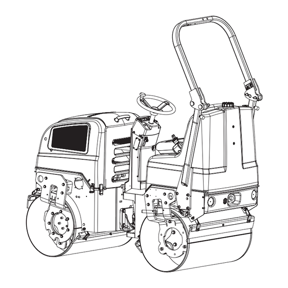
Introduction Introduction The machine Dynapac CC900G is a self-propelled vibratory tandem roller in the 1,6 metric tonnes class featuring 900 mm wide drums. The machine is equipped with drive, brakes, and vibration on both drums. Intended use CC900G is primarily used for smaller compaction works, such as minor roads, sidewalks, cycle ways and minor parking places. -
Page 10: General
Introduction Prevent persons from entering or remaining in Prevent persons from entering or remaining in the danger area, i.e. a distance of at least 7 m the danger area, i.e. a distance of at least 7 m (23 ft) in all directions from operating machines. (23 ft) in all directions from operating machines. -
Page 11: Safety - General Instructions
Safety - General instructions Safety - General instructions (Also read the safety manual) The operator must be familiar with the contents of the OPERATION section The operator must be familiar with the contents of the OPERATION section before starting the roller. before starting the roller. - Page 12 Safety - General instructions 16. Hearing protection is recommended if the noise level exceeds 85 dB(A). The 16. Hearing protection is recommended if the noise level exceeds 85 dB(A). The noise level can vary depending on the equipment on the machine and the noise level can vary depending on the equipment on the machine and the surface the machine is being used on.
-
Page 13: Safety - When Operating
Safety - when operating Safety - when operating Prevent persons from entering or remaining in Prevent persons from entering or remaining in the danger area, i.e. a distance of at least 7 m the danger area, i.e. a distance of at least 7 m (23 ft) in all directions from operating machines. -
Page 14: Driving Near Edges
Safety - when operating Driving near edges When driving near an edge, minimum 2/3 of the drum width must be on solid ground. Keep in mind that the machine’s center of Keep in mind that the machine’s center of gravity moves outwards when steering. For gravity moves outwards when steering. -
Page 15: Sitting Position
Safety - when operating Sitting position Remain seated at all times when operating the roller. Always use the seat belt where fitted. Where the Always use the seat belt where fitted. Where the seat belt is not used, there is a great risk that the seat belt is not used, there is a great risk that the operator will be thrown off and land under the operator will be thrown off and land under the... - Page 16 Safety - when operating 4812274432.pdf 2017-07-10...
-
Page 17: Special Instructions
Special instructions Special instructions Standard lubricants and other recommended oils and fluids Before leaving the factory, the systems and components are filled with the oils and fluids specified in the lubricant specification. These are suitable for ambient temperatures in the range -15°C to +40°C (5°F - 105°F). -
Page 18: Roll Over Protective Structure (Rops)
Special instructions Roll Over Protective Structure (ROPS) Never carry out any welding or drilling Never carry out any welding or drilling operations of any kind on the Roll Over operations of any kind on the Roll Over Protective Structure (ROPS). Protective Structure (ROPS). -
Page 19: Jump Starting
Special instructions Jump starting Do not connect the negative cable to the Do not connect the negative cable to the negative terminal on the dead battery. A spark negative terminal on the dead battery. A spark can ignite the oxy-hydrogen gas formed can ignite the oxy-hydrogen gas formed around the battery. - Page 20 Special instructions 4812274432.pdf 2017-07-10...
-
Page 21: Technical Specifications - Noise/Vibrations/Electrical
Technical specifications - Noise/Vibrations/Electrical Technical specifications - Noise/Vibrations/Electrical Vibrations - Operator station (ISO 2631) The vibration levels are measured in accordance with the operational cycle described in The vibration levels are measured in accordance with the operational cycle described in EU directive 2000/14/EC on machines equipped for the EU market, with vibration switched EU directive 2000/14/EC on machines equipped for the EU market, with vibration switched on, on soft polymer material and with the operator’s seat in the transport position. - Page 22 Technical specifications - Noise/Vibrations/Electrical 4812274432.pdf 2017-07-10...
-
Page 23: Technical Specifications - Dimensions
Technical specifications - Dimensions Technical specifications - Dimensions Dimensions, side view Dimensions Dimensions Wheelbase Wheelbase 1350 1350 53,1 53,1 Drum diameter Drum diameter 23,0 23,0 Height, with ROPS Height, with ROPS 2300 2300 90,5 90,5 Height, w/o ROPS Height, w/o ROPS 1585 1585 62,4... -
Page 24: Dimensions, Top View
Technical specifications - Dimensions Dimensions, top view Dimensions Dimensions Width Width 38,2 38,2 Overhang Overhang 1,38 1,38 Turning radius, outside Turning radius, outside 2700 2700 106,3 106,3 2660 2660 104,7 104,7 Drum shell thickness Drum shell thickness 35,4 35,4 α α... -
Page 25: Weights And Volumes
Technical specifications - Dimensions Weights and volumes Weights Service weight with ROPS Service weight with ROPS 1335 kg 1335 kg 2943 lbs 2943 lbs (EN500) (EN500) Weights Service weight with ROPS Operating mass 1335 kg 1250 kg 2943 lbs 2767 lbs (EN500) (EN500) Fluid volumes... -
Page 26: General
Technical specifications - Dimensions General Manufacturer/Model Manufacturer/Model Honda GX630 Honda GX630 Output at 3,600 rpm (SAE J1349) Output at 3,600 rpm (SAE J1349) 15,5 kW / 21 Hp 15,5 kW / 21 Hp Electrical system Electrical system Battery Battery 12V 60Ah 12V 60Ah Charging coil Charging coil... -
Page 27: Rops - Bolts
Technical specifications - Dimensions ROPS - bolts Bolt dimensions : Bolt dimensions : M12 (PN 508063) M12 (PN 508063) Strength class : Strength class : Tightening torque : Tightening torque : 70 Nm 70 Nm ROPS-bolts which are to be torque tightened ROPS-bolts which are to be torque tightened must be dry. -
Page 28: Product Identification Number On The Frame
Technical specifications - Dimensions Product identification number on the frame The machine PIN (Product Identification Number) (1) is punched on the right edge of the front frame. Fig. PIN Front frame 4812274432.pdf 2017-07-10... -
Page 29: Engine Plates
Technical specifications - Dimensions Engine plates The engine serial number (1) is punched below the starter. Please specify the engine serial number when ordering spares. Refer also to the engine manual. The engine's EPA plate (2). Figure. Engine 1. Serial number 2. - Page 30 Machine description- Decals 4812274432.pdf 2017-07-10...
-
Page 31: Machine Description- Decals
Machine description- Decals Machine description- Decals Location - decals 1, 9 Fig. Location, decals and signs Warning, Crush zone Warning, Crush zone 4700903422 4700903422 Lifting point Lifting point 4700357587 4700357587 Warning, Rotating engine components 4700903423 Warning, Rotating engine components 4700903423 Hydraulic fluid level Hydraulic fluid level 4700272373... -
Page 32: Safety Decals
Machine description- Decals Safety decals Always make sure that all safety decals are completely legible, and remove dirt or order new decals if they have become illegible. Use the part number specified on each decal. 4700903422 Warning - Crush zone, articulation/drum. Maintain a safe distance from the crush zone. -
Page 33: Info Decals
Machine description- Decals Info decals Handbook compartment Handbook compartment Petrol Petrol Lifting point Lifting point Hydraulic oil level Hydraulic oil level Hoisting plate Hoisting plate Securing point Securing point 2017-07-10 4812274432.pdf... -
Page 34: Instruments/Controls
Machine description- Decals Instruments/Controls Locations - Instruments and controls 1. Ignition key 7. Fuse box 2. Control, engine speed 8. Sprinkler 3. Parking brake 9. Horn 4. Vibration on/off, switch 10. Emergency stop 5. Fuel level, hour meter 11. Choke 6. -
Page 35: Function Description
Machine description- Decals Function description Designation Designation Symbol Symbol Function Function Starter switch The electric circuit is broken. All instruments and electrical controls are supplied with power Starter motor activation. Control, engine speed Pull the lever up to obtain working speed. Move the lever down to obtain idling speed. -
Page 36: Electrical System
Machine description- Decals Electrical system Relays and fuses on the machine The figure shows the positions of the various fuses and relays. The table below gives their amperage and function. All fuses are flat pin fuses. Relays Relays Starting Starting 12V 30A 12V 30A Start, vibration, brake... -
Page 37: Operation
Operation Operation Before starting Operator’s seat - Adjusting Adjust the operator’s seat so that the position is comfortable and so that the controls are within easy reach. The seat can be adjusted lengthways (1). Fig. Operator's seat 1. Length adjustment Sprinkler - Check Make sure that the emergency stop knob is actually pressed in. -
Page 38: Parking Brake
Operation Parking brake Activate parking brake before leaving the machine. The machine starts with the parking brake deactivated. Emergency stop The machine starts with emergency stop pulled out. Figure. Control panel 3. Parking brake 10. Emergency stop Operator position Replace the seat belt (1) if it shows signs of Replace the seat belt (1) if it shows signs of wear or has been subjected to high levels of wear or has been subjected to high levels of... -
Page 39: Starting
Operation Starting Starting the engine Make sure that the parking brake knob (3) is activated. Sit down in the operator's seat and set the forward/reverse lever (6) in neutral. You cannot start the petrol engine with the lever in any other position. Set the RPM control (2) to idle. -
Page 40: Driving
Operation Carefully move the forward/reverse lever (6) forwards or backwards, depending on which direction of travel is required. Speed increases as the lever is moved away from the neutral position. The speed should always be controlled using the The speed should always be controlled using the forward/reverse lever and never by changing the forward/reverse lever and never by changing the engine speed. -
Page 41: Vibration
Operation Vibration Manual vibration - Switching on Vibration should not be active when the roller is Vibration should not be active when the roller is stationary. This can damage both the surface and stationary. This can damage both the surface and the machine. - Page 42 Operation 4812274432.pdf 2017-07-10...
-
Page 43: Operating - Stopping
Operating - Stopping Operating - Stopping Braking Normal braking When starting and driving a machine that is cold, When starting and driving a machine that is cold, remember that the hydraulic fluid is also cold and remember that the hydraulic fluid is also cold and that braking distances can be longer than normal that braking distances can be longer than normal until the machine reaches the working temperature. -
Page 44: Reserve Brake
Operating - Stopping Reserve brake Braking is normally activated using the forward/reverse lever. The hydrostatic transmission retards and slows the roller when the lever is moved towards the neutral position. A disc brake in each drum motor acts as reserve brake when in motion and as a parking brake when stationary. -
Page 45: Parking
Operating - Stopping Parking Chocking the drums Never disembark from the machine when the is Never disembark from the machine when the is engine running, unless the reserve/parking brake engine running, unless the reserve/parking brake knob is depressed. knob is depressed. Make sure that the roller is parked in a safe place Make sure that the roller is parked in a safe place with respect to other road users. -
Page 46: Long-Term Parking
Long-term parking Long-term parking The following instructions should be followed The following instructions should be followed when long term parking (more than one month). when long term parking (more than one month). These measures apply when parking for a period of up to 6 months. -
Page 47: Steering Cylinder, Hinges, Etc
Long-term parking Steering cylinder, hinges, etc. Grease the steering cylinder piston with conservation grease. Grease the hinges on the doors to the engine compartment. Grease both ends of the forward/reverse control (bright parts) (see under the heading ‘Every 500 hours of operation’). Hoods, tarpaulin * Lower the instrument cover over the instrument panel. -
Page 48: Engine
Long-term parking Engine * Below description quote from manufacturer’s instructions in the engine manual that is supplied with the roller. STORING YOUR ENGINE Draining the Fuel Tank and Carburetor Storage Preparation Proper storage preparation is essential for keeping your engine trouble-free and looking good. -
Page 49: Miscellaneous
Miscellaneous Miscellaneous Locking the articulation Turn the steering wheel to the straight ahead position. Raise the locking arm (1) and turn 180 degrees downward. Ensure that the cotter pin (2) is guided into its lower position correctly for locking the articulation. Fig. -
Page 50: Securing Cc900G For Loading
Miscellaneous Securing CC900G for loading Securing the CC900G vibratory roller from Dynapac for transport. Roller loaded in forward direction Direct of travel 1 - 2 1 - 2 = double lashings, i.e. one lashing with two parts secured to two different lashing mounts, = double lashings, i.e. -
Page 51: Towing
Miscellaneous Load carrier Load carrier When loaded, the vibratory roller is centered laterally on the platform (± 5 cm). When loaded, the vibratory roller is centered laterally on the platform (± 5 cm). The parking brake is applied and in good working condition, and the articulated joint lock is The parking brake is applied and in good working condition, and the articulated joint lock is closed. - Page 52 Miscellaneous Figure. Releasing the brake 2. Press the screws (192) inwards to compress the springs (193) so that the screw reaches the brake (107) inner thread. 3. Tighten the two screws (192) alternately a little at a time so that the brake piston (107) loose (screw approximately 2 turns).
-
Page 53: Towing The Roller
Miscellaneous Tightening torque Tightening torque Screws (192) Screws (192) Plugs (191) Plugs (191) Towing the roller A towing bar must be used when towing, as the A towing bar must be used when towing, as the roller has no brakes and can only be slowed and roller has no brakes and can only be slowed and stopped by the vehicle towing the roller. - Page 54 Operating instructions - Summary 4812274432.pdf 2017-07-10...
-
Page 55: Operating Instructions - Summary
Operating instructions - Summary Operating instructions - Summary Follow the SAFETY INSTRUCTIONS specified in the Safety Manual. Follow the SAFETY INSTRUCTIONS specified in the Safety Manual. Make sure that all instructions in the MAINTENANCE section are followed. Make sure that all instructions in the MAINTENANCE section are followed. Set the reserve/parking brake to its pulled-out position. - Page 56 Operating instructions - Summary 4812274432.pdf 2017-07-10...
-
Page 57: Preventive Maintenance
Preventive maintenance Preventive maintenance Complete maintenance is necessary for the machine to function satisfactorily and at the lowest possible cost. The Maintenance section includes the periodic maintenance that must be carried out on the machine. The recommended maintenance intervals assume that the machine is used in a normal environment and working conditions. - Page 58 Preventive maintenance 4812274432.pdf 2017-07-10...
-
Page 59: Maintenance - Lubricants And Symbols
Maintenance - Lubricants and symbols Maintenance - Lubricants and symbols Always use high-quality lubricants and the Always use high-quality lubricants and the amounts recommended. Too much grease or amounts recommended. Too much grease or oil can cause overheating, resulting in rapid oil can cause overheating, resulting in rapid wear. - Page 60 Maintenance - Lubricants and symbols ENGINE OIL ENGINE OIL Air temperature -15°C - +50°C Air temperature -15°C - +50°C P/N 5580020624 (5 litres) P/N 5580020624 (5 litres) AtlasCopco Engine 100 (5°F-122°F) (5°F-122°F) , API CH-4 P/N 5501522700 (20 litres) P/N 5501522700 (20 litres) HYDRAULIC FLUID HYDRAULIC FLUID Air temperature -15°C - +40°C...
-
Page 61: Maintenance Symbols
Maintenance - Lubricants and symbols Maintenance symbols Engine, oil level Engine, oil level Air filter Air filter Engine, oil filter Engine, oil filter Battery Battery Hydraulic reservoir, level Hydraulic reservoir, level Sprinkler Sprinkler Hydraulic fluid, filter Hydraulic fluid, filter Sprinkler water Sprinkler water Drum, oil level Drum, oil level... - Page 62 Maintenance - Lubricants and symbols 4812274432.pdf 2017-07-10...
-
Page 63: Maintenance - Maintenance Schedule
Maintenance - Maintenance schedule Maintenance - Maintenance schedule Service and maintenance points 12, 13 Fig. Service and maintenance points 1. Water tank, filling 1. Water tank, filling 7. Air cleaner 7. Air cleaner 13. Hydraulic fluid, filling 13. Hydraulic fluid, filling 2. -
Page 64: General
Maintenance - Maintenance schedule General Periodic maintenance should be carried out after the number of hours specified. Use the daily, weekly etc. periods where number of hours cannot be used. Remove all dirt before filling, when checking Remove all dirt before filling, when checking oils and fuel and when lubricating using oil or oils and fuel and when lubricating using oil or grease. -
Page 65: After The First 50 Hours Of Operation
Maintenance - Maintenance schedule After the FIRST 50 hours of operation Refer to the contents to find the page number of the sections referred to ! Action Action Comment Comment Change the hydraulic fluid filter Change the hydraulic fluid filter Every 50 hours of operation Refer to the contents to find the page number of the sections referred to ! -
Page 66: Every 200 / 400 / 600 / 800 Hours Of Operation
Maintenance - Maintenance schedule Every 200 / 400 / 600 / 800 hours of operation Refer to the contents to find the page number of the sections referred to ! Pos. Pos. Action Action Comment Comment in fig in fig Replace the spark plugs Replace the spark plugs Refer to the engine manual. -
Page 67: Every 1000 Hours Of Operation
Maintenance - Maintenance schedule Every 1000 hours of operation Refer to the contents to find the page number of the sections referred to ! Pos. Pos. Action Action Comment Comment in fig in fig Replace the spark plugs Replace the spark plugs Refer to the engine manual. -
Page 68: Every 2000 Hours Of Operation
Maintenance - Maintenance schedule Every 2000 hours of operation Refer to the contents to find the page number of the sections referred to ! Pos. Pos. Action Action Comment Comment in fig in fig Replace the spark plugs Replace the spark plugs Refer to the engine manual Refer to the engine manual Check idling revs... -
Page 69: Maintenance - Maintenance Measures, Before Use
Maintenance - Maintenance measures, before use Maintenance - Maintenance measures, before use Park the roller on a level surface. Park the roller on a level surface. When checking and making adjustments, the When checking and making adjustments, the engine should be switched off and the engine should be switched off and the emergency/parking brake should be applied, if emergency/parking brake should be applied, if... - Page 70 Maintenance - Maintenance measures, before use 4812274432.pdf 2017-07-10...
-
Page 71: Maintenance, 10H
Maintenance, 10h Maintenance, 10h Park the roller on a level surface. Park the roller on a level surface. When checking and making adjustments, the When checking and making adjustments, the engine should be switched off and the engine should be switched off and the emergency/parking brake should be applied, if emergency/parking brake should be applied, if not otherwise specified. -
Page 72: Refueling
Maintenance, 10h Refueling Refuel the tank every day before starting work. Open the tank cap and fill through the filler pipe (1). Never refuel while the engine is running. Do not Never refuel while the engine is running. Do not smoke and avoid spilling fuel. -
Page 73: Air Circulation - Check
Maintenance, 10h Air circulation - Check Ensure that the petrol engine has free circulation of cooling air through the vents in the hood. Fig. Engine cover 1. Cooling air grille/engine Scrapers - Check, adjustment Make sure that the scrapers are undamaged. Adjust the scrapers if necessary in the following way: For firmer application of the scraper, undo the locking nut (2) and turn it to the right until the desired... -
Page 74: Air Cleaner - Check
Maintenance, 10h Air cleaner - check Check that hoses and couplings are not leaking and that the air cleaner cover is on properly. Clean the air cleaner when operated in extremely dusty environments. Fig. Engine 1. Air filter 4812274432.pdf 2017-07-10... -
Page 75: Maintenance - 20H
Maintenance - 20h Maintenance - 20h Park the roller on a level surface. Park the roller on a level surface. When checking and making adjustments, the When checking and making adjustments, the engine should be switched off and the engine should be switched off and the emergency/parking brake should be applied, if emergency/parking brake should be applied, if not otherwise specified. - Page 76 Maintenance - 20h Fit the drain plug (2) to the end of the hose. Fill with fresh engine oil (see under Lubricants heading for the correct oil grade), refit the filler cap (4) and check the level on the dipstick. Start the engine and check the tightness around the oil filter.
-
Page 77: Maintenance - 50H
Maintenance - 50h Maintenance - 50h Park the roller on a level surface. Park the roller on a level surface. When checking and making adjustments, the When checking and making adjustments, the engine should be switched off and the engine should be switched off and the emergency/parking brake should be applied, if emergency/parking brake should be applied, if not otherwise specified. -
Page 78: Air Cleaner - Cleaning
Maintenance - 50h Air cleaner - cleaning Unclip the four lock catches (1) and lift the air cleaner's cover (2). Lift out the plastic foam and clean it in warm soapy water, rinse and dry. Clean the air filter by tapping it with the palm of the hand or blow compressed air (not exceeding 207 kPa (2,1 kgf/cm2, 30 psi)) through the filter element from the air cleaner case side. -
Page 79: Maintenance - 100H
Maintenance - 100h Maintenance - 100h Park the roller on a level surface. Park the roller on a level surface. When checking and making adjustments, the When checking and making adjustments, the engine should be switched off and the engine should be switched off and the emergency/parking brake should be applied, if emergency/parking brake should be applied, if not otherwise specified. - Page 80 Maintenance - 100h 4812274432.pdf 2017-07-10...
-
Page 81: Maintenance - 200 / 400 / 600 / 800 H
Maintenance - 200 / 400 / 600 / 800 h Maintenance - 200 / 400 / 600 / 800 h Park the roller on a level surface. Park the roller on a level surface. When checking and making adjustments, the When checking and making adjustments, the engine should be switched off and the engine should be switched off and the... -
Page 82: Engine's Fuel Filter - Check
Maintenance - 200 / 400 / 600 / 800 h Engine's fuel filter - Check Switch off the engine and push in the Switch off the engine and push in the reserve/parking brake knob. reserve/parking brake knob. Use caution. Wear gloves. Use caution. -
Page 83: Engine Oil And Oil Filter - Change
Maintenance - 200 / 400 / 600 / 800 h Engine oil and oil filter - Change Run the engine until it is warm before draining the oil. Switch off the engine and push in the Switch off the engine and push in the reserve/parking brake knob. -
Page 84: Forward/Reverse Controls And Joints - Check And Lubrication
Maintenance - 200 / 400 / 600 / 800 h Forward/Reverse controls and joints - Check and lubrication Unscrew the protective plate. Check the friction on the forward/reverse lever. The friction nut (1) should be applied with sufficient pressure to keep the forward/reverse lever in the set position during operation. -
Page 85: Maintenance - 500H
Maintenance - 500h Maintenance - 500h Park the roller on a level surface. Park the roller on a level surface. When checking and making adjustments, the When checking and making adjustments, the engine should be switched off and the engine should be switched off and the emergency/parking brake should be applied, if emergency/parking brake should be applied, if not otherwise specified. -
Page 86: Hydraulic Reservoir - Check/Venting
Maintenance - 500h Hydraulic reservoir - Check/venting Unscrew and make sure that the reservoir cap is not blocked. Air must have unobstructed passage through the cap in both directions. If blocked in either direction, clean with a little diesel oil and blow with compressed air until unblocked or replace the cap with a new one. -
Page 87: Air Cleaner - Replace Insert
Maintenance - 500h Air cleaner - replace insert Pull the air cleaner cover latch (1) to the unlocked position and remove the cover (2). Remove the wing nut (3) from the filter element (4). Lift out the foam filter element (8) and the filter element (4). - Page 88 Maintenance - 500h 4812274432.pdf 2017-07-10...
-
Page 89: Maintenance - 1000H
Maintenance - 1000h Maintenance - 1000h Park the roller on a level surface. Park the roller on a level surface. When checking and making adjustments, the When checking and making adjustments, the engine should be switched off and the engine should be switched off and the emergency/parking brake should be applied, if emergency/parking brake should be applied, if not otherwise specified. -
Page 90: Engine's Fuel Filter - Replace
Maintenance - 1000h Engine's fuel filter - Replace Switch off the engine and push in the Switch off the engine and push in the reserve/parking brake knob. reserve/parking brake knob. Use caution. Wear gloves. Use caution. Wear gloves. Replace the fuel filter (1). Refer to the engine manual for detailed Refer to the engine manual for detailed Fig. -
Page 91: Forward/Reverse Controls And Joints - Check And Lubrication
Maintenance - 1000h Forward/Reverse controls and joints - Check and lubrication Unscrew the protective plate. Check the friction on the forward/reverse lever. The friction nut (1) should be applied with sufficient pressure to keep the forward/reverse lever in the set position during operation. -
Page 92: Front Drum - Checking The Oil Level
Maintenance - 1000h Front drum - Checking the oil level Park the roller on a level surface, and drive the roller slowly until the oil plug (1) is in the middle of the semicircle shaped notch in the drum suspension. Switch off the engine, disconnect the power and Switch off the engine, disconnect the power and push in the reserve/parking brake knob. -
Page 93: Steering Joint - Check
Maintenance - 1000h Steering joint - Check Inspect the steering joint to detect any damage or cracks. Check and tighten any loose bolts. Check also for any stiffness and play in the steering joint. Rectify if necessary. Fig. Steering joint Air cleaner - replace insert Pull the air cleaner cover latch (1) to the unlocked position and remove the cover (2). -
Page 94: Hydraulic Fluid Filter - Change
Maintenance - 1000h Hydraulic fluid filter - Change Remove the filter (1) and deliver to special waste Remove the filter (1) and deliver to special waste handling. This is a single-use filter and cannot be handling. This is a single-use filter and cannot be cleaned. -
Page 95: Engine's Fuel Filter - Check
Maintenance - 1000h Undo the oil filler cap (4) and remove the plug (2) from the end of the drain hose (1); allow all the engine oil to run out. Deliver the drained oil to special waste handling. Deliver the drained oil to special waste handling. Refer to the engine manual for detailed Refer to the engine manual for detailed instructions when changing oil and filters. - Page 96 Maintenance - 1000h 4812274432.pdf 2017-07-10...
-
Page 97: Maintenance - 2000H
Maintenance - 2000h Maintenance - 2000h Park the roller on a level surface. Park the roller on a level surface. When checking and making adjustments, the When checking and making adjustments, the engine should be switched off and the engine should be switched off and the emergency/parking brake should be applied, if emergency/parking brake should be applied, if not otherwise specified. -
Page 98: Engine's Fuel Filter - Replace
Maintenance - 2000h Engine's fuel filter - Replace Switch off the engine and push in the Switch off the engine and push in the reserve/parking brake knob. reserve/parking brake knob. Use caution. Wear gloves. Use caution. Wear gloves. Replace the fuel filter (1). Refer to the engine manual for detailed Refer to the engine manual for detailed Fig. -
Page 99: Forward/Reverse Controls And Joints - Check And Lubrication
Maintenance - 2000h Forward/Reverse controls and joints - Check and lubrication Unscrew the protective plate. Check the friction on the forward/reverse lever. The friction nut (1) should be applied with sufficient pressure to keep the forward/reverse lever in the set position during operation. -
Page 100: Steering Joint - Check
Maintenance - 2000h Steering joint - Check Inspect the steering joint to detect any damage or cracks. Check and tighten any loose bolts. Check also for any stiffness and play in the steering joint. Rectify if necessary. Fig. Steering joint Air cleaner - replace insert Pull the air cleaner cover latch (1) to the unlocked position and remove the cover (2). -
Page 101: Hydraulic Fluid Filter - Change
Maintenance - 2000h Hydraulic fluid filter - Change Remove the filter (1) and deliver to special waste Remove the filter (1) and deliver to special waste handling. This is a single-use filter and cannot be handling. This is a single-use filter and cannot be cleaned. - Page 102 Maintenance - 2000h Undo the oil filler cap (4) and remove the plug (2) from the end of the drain hose (1); allow all the engine oil to run out. Deliver the drained oil to special waste handling. Deliver the drained oil to special waste handling. Refer to the engine manual for detailed Refer to the engine manual for detailed instructions when changing oil and filters.
-
Page 103: Hydraulic Reservoir - Fluid Change
Maintenance - 2000h Hydraulic reservoir - fluid change Use an external drainage pump when draining/emptying the hydraulic reservoir. Danger of being burned when draining hot oil. Danger of being burned when draining hot oil. Wear gloves and eye protectors. Wear gloves and eye protectors. Unscrew the reservoir cap. -
Page 104: Front Drum - Changing The Oil
Maintenance - 2000h Front drum - Changing the oil Loosen the oil plug (1) slightly, when it is in position for level check (2), so that it can subsequently be unscrewed by hand. Park the roller on a level surface, and drive the roller slowly until the plug (1) is in the bottom position.
Need help?
Do you have a question about the Dynapac CC900G and is the answer not in the manual?
Questions and answers