Table of Contents
Advertisement
Advertisement
Chapters
Table of Contents
Troubleshooting

Related Manuals for Giant MY20


Summary of Contents for Giant MY20
- Page 1 MY20 SERVICE MANUAL...
-
Page 3: Table Of Contents
TABLE OF CONTENTS 1. Intro ......................2. MY20 G-Systems components overview .........7 3. Tools ....................... 4. Assembly guides ................5. Trouble shooting ................81 6. Supplement .................. -
Page 5: Intro
MANUAL MY20. This Service Manual contains specific information about the e-bike system components of recent Giant, Liv & Momentum e-bikes. It is designed to be used by a workshop mechanic, as a technical guide and reference work for servicing our E-Bikes. -
Page 7: My20 G-Systems Components Overview
2. MY20 G-SYSTEMS COMPONENTS OVERVIEW CHAPTER CONTENTS G-System ..................SyncDrive ..................SyncDrive Pro MY20 ................9 SyncDrive Sport .................. SyncDrive Life ..................13 Pedalplus ................... 6-sensor technology ................RideControl .................. RideControl One ..................17 RideControl Evo .................. RideControl Charge ................25 Remote (charge & Evo) .............. -
Page 8: G-System
The SyncDrive motors contain the main processing unit and all but one of the sensors. There are 3 different types of SyncDrive motors in MY20: Life, Sport & Pro. All three are updated with the latest 6-sensor technology. For MY20 the output for lights has also been increased to 9 Watt max. -
Page 9: Syncdrive
128mm wide Hollow BB axle with ISIS interface SMART ASSIST: Each MY20 SyncDrive Motor is equipped with PedalPlus 6-sensor tech- nology. Switching the assist level down to off, and then one level further, acti- vates the Smart Assist function (AUTO mode). The Smart Assist will automat- ically select the optimal power ratio depending on the input of all six sensors. - Page 10 Giant Service Tool software and dongle. SENSORS: The MY20 SyncDrive Pro motor uses PedalPlus 6 sensor technology to op- erate: Speed, pedaling torque, pedaling cadence, motor rpm, slope & accel- eration. More information about the sensors can be found in the PedalPlus chapter further on in this manual.
-
Page 11: Syncdrive Sport
Square taper (JIS) BB axle SMART ASSIST: Each MY20 SyncDrive Motor is equipped with PedalPlus 6-sensor tech- nology. Switching the assist level down to off, and then one level further, acti- vates the Smart Assist function (AUTO mode). The Smart Assist will automat- ically select the optimal power ratio depending on the input of all six sensors. - Page 12 Dealers have read access to certain information stored in the motor, like error codes and motor ODO, by using the Giant Service Tool software and dongle. SENSORS: The SyncDrive Sport motor uses PedalPlus 6 sensor technology to operate: Speed, pedaling torque, pedaling cadence, motor rpm, slope &...
-
Page 13: Syncdrive Life
Square taper (JIS) BB axle SMART ASSIST: Each MY20 SyncDrive Motor is equipped with PedalPlus 6-sensor tech- nology. Switching the assist level down to off, and then one level further, acti- vates the Smart Assist function (AUTO mode). The Smart Assist will automat- ically select the optimal power ratio depending on the input of all six sensors. - Page 14 Dealers have read access to certain information stored in the motor, like error codes and motor ODO, by using the Giant Service Tool software and dongle. SENSORS: The SyncDrive Life motor uses PedalPlus 6 sensor technology to operate: Speed, pedaling torque, pedaling cadence, motor rpm, slope &...
-
Page 15: Pedalplus
6. INTEGRATED SPEED SENSOR New in MY20 is the integrated speed sensor. This sensor works the same as the external sensor, but is integrated into the left rear dropout. The magnet is mounted on the disc-brake rotor using 2 of the 6 rotor mounting bolts. - Page 16 SMART ASSIST The six separate sensor signals are processed by the G-System software, which optimizes the motor output while riding within any set assist mode. The Smart Assist mode (Auto) goes a step further, by using the sensor data to continuously adjust and balance the power ratio automatically between the available 50-360% (depending on motor type).
-
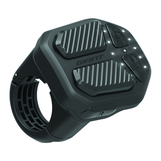
Page 17: Ridecontrol
LED lights. ANT+ In MY20, ANT+ connectivity is added to the RideControl One. Bike computers and other devices that support the ANT+ LEV (Light Electric Vehicle) profile can display various E-bike fields, like battery capacity, remaining range and assist level. - Page 18 LED INDICATORS: BATTERY CHARGE LEVEL INDICATOR The row of 5 LEDS (B1 - B5) located near the edge of the RideControl One indicate the battery charge level. Each LED represents a block of approx. 20% battery charge. So when all battery LEDS are on, this would mean that the battery is charged to about 80-100%.
- Page 19 ASSIST LEVEL INDICATOR The row of 5 LEDS (L1 - L5) located next to the Assist UP/DOWN buttons indicate the selected assist level. More lights on means more power assist. When all assist lights are off, the motor assist will be off. SMART ASSIST INDICATOR Press Assist Down button a few times down to Assist OFF, and 1 press more to activate the Smart Assist function.
- Page 20 ERRORS In the case of an error, the RideControl One will indicate with the LT LED blinking in red that there is an error, and one of the white Assist LEDS (L1, L2, L3 or L5). will blink to show which component the error is related to. Below an overview of the errors the RideControl One can show.
- Page 21 Ride Control. Older hardware & firmware versions have a very simple sequence (Method 1), later versions have a slightly modified sequence (Method 2), to prevent activating low speed mode by accident. MY20 bikes all have firmware with method 2, modified button sequence...
-
Page 22: Ridecontrol Evo
RIDECONTROL EVO The RideControl EVO remains a core item in MY20 and keeps evolving with new firmware updates, adding improvements and functionalities. OPERATION The remote is used for all control of the RideControl EVO functions. For in- formation on how to operate the EVO display, please refer to the e-bike user manual. - Page 23 EVO screen, indicating that the user should go to the dealer for maintenance. Currently dealers can follow their own procedure for service intervals. A list of advised maintenance intervals and procedures will be released in MY20. GIVEN ODO SETTING The SyncDrive ODO is stored in the motor and will start counting from the moment it is in use.
- Page 24 ERRORS If an error occurs, the RideControl EVO will notify the user. There are 5 error that could be displayed: • SyncDrive error • Speed sensor error • EnergyPak error • Bluetooth error • RideControl error The RideControl will show a sequence of messages, before returning back to the normal riding screen.
-
Page 25: Ridecontrol Charge
RIDECONTROL CHARGE The MY20 Charge displays are compatible with 5 assist modes and Smart Assist. It is also possible to update the firmware, display cadence rpm, set the Given ODO, and connect to the RideControl app. Charge display COMPATIBILITY The Charge display connects to all G-system bikes, just like EVO and RC One. - Page 26 Currently dealers can follow their own procedure for service intervals. A list of advised maintenance intervals and procedures will be released in MY20. GIVEN ODO SETTING The SyncDrive ODO is stored in the motor will start counting from the mo- ment it is in use.
-
Page 27: Remote (Charge & Evo)
diagnose process. The Extensive Service Tool report will contain all the test results and detailed error codes. These codes are explained in the specific Service Tool Manual (PDF) that comes with the Service software. REMOTE (CHARGE & EVO) There is one type of remote controller. It has six buttons and one type of connector for the G-system;... -
Page 28: Ridecontrol Features Overview
RIDECONTROL FEATURES OVERVIEW FEATURE CHARGE • (5 blocks) • (10 blocks) • (5 leds) EnergyPak Capacity (block) RANGE • • • On connected device* EnergyPak Capacity % • • • On connected device* Remaining Range • (6 modes + off) •... -
Page 29: Energypak
• 400Wh ENERGYPAK SMART In MY20, the integrated EnergyPaks got a few updated internals and up- dated Battery Management System (BMS) These EnergyPaks are now called EnergyPak Smart. Among other small improvements, the update makes them compatible with accessories like EnergyPak Plus (Range extender battery). -
Page 30: The First Charge (All Energypaks)
SYNCDRIVE PRO ENERGYPAK MODE RANGE (KM) MODE RANGE (KM) MODE RANGE (KM) 500WH Eco+ Eco+ Basic Integrated (MY19) Normal Normal Active 244M36500I-01V Smart (MY20) Sport Sport Sport 244M36500I-03V Sport+ Sport+ Power Eco+ Eco+ Basic 400WH Normal Normal Active Sport Sport... -
Page 31: Charger
In MY20 a new Smart Charger version is added, with an 90 degree angled charge plug. It functions exactly the same as the existing Smart Charger, but this charger works only with 220V AC outlets. -
Page 32: Charging Duration Table
CHARGING DURATION TABLE Below table indicates charge times for different batteries derived from calculations and testing. These times can vary, depending on various factors like ambient temperature, battery health etc. 110V AC 220V AC 100-240V AC 3A FAST CHARGER 4A FAST CHARGER 6A SMART CHARGER 400WH 500WH... -
Page 33: Tools
3. TOOLS TABLE OF CONTENTS Giant specific tools and general tools ..........34 Service tool software & USB dongle ..........35 Sockets and keys ................35 Speed sensor and integrated battery lock ........35 Spider socket, 2-sprocket spider .............36 Spider socket, 8 notch ..............36 Torque tool ..................36... -
Page 34: Giant Specific Tools And General Tools
3.1 GIANT SPECIFIC TOOLS AND GENERAL TOOLS In order to perform best maintenance and repairs on G-System E-bikes, some general and specific tools are required, such as: • Service Tool, software & USB Dongle (Giant specific) • Sockets, wrenches and keys (Giant specific) •... -
Page 35: Service Tool Software & Usb Dongle
PC running the Service Tool software. The software provides step-by-step walkthroughs for diagnostics of all G-system components on Giant E-bikes. It collects data from various compo- nents of the E-Bike, has built-in solutions and assembly guides for a majority of issues that could arise, and can export the results in detailed reports. -
Page 36: Spider Socket, 2-Sprocket Spider
SyncDrive Sport motor, a conventional 36mm hex-socket will not fit, because the outside diameter is too large to fit the spider. A special socket with smaller outside diameter can be ordered from Giant: 2520-36NUT-02V. Security Torx key: Socket M36 for 3/8” Torque... -
Page 37: Battery Capacity Tester & Cable
3.5 BATTERY CAPACITY TESTER & CABLE G-system battery quality can be checked quickly and easily with the Service Tool Software, so the Battery Capacity Tester (5481-test-06V) is not neces- sary for these batteries. For discharging EnergyPak battery, the capacity tester is still usefull. A: Power On/Off switch Switches the tester On or Off. -
Page 38: Multimeter
It is not the intention of this manual to elaborate on this subject. For G-system, the Service Tool (and some additional spare parts) should suffice for diagnosing most issues. If this is somehow not the case, the Giant service department can provide further information and guidance. -
Page 39: Assembly Guides
4. ASSEMBLY GUIDES TABLE OF CONTENTS SyncDrive - motor ................SyncDrive Pro motor ................. SyncDrive Comfort / Sport / Life motor ..........43 Battery connector spacer ..............45 SyncDrive external speed sensor ............ Integrated speed sensor replacement ........... RideControl – remote & display ............52 Remote button &... -
Page 40: Syncdrive - Motor
4.1 SYNCDRIVE - MOTOR SYNCDRIVE PRO MOTOR Motors can only be serviced by Giant Service Center. Contact your local Giant Service Center for further directions. DISASSEMBLE General operational procedures, to be taken into account before any repairs are done. • Remove the battery, to prevent accidental motor support engagement! •... - Page 41 Loosen and remove all motor cover bolts. For Full Suspension bikes: Slightly loosen battery connector cover/base plate bolts (just a few turns anti- clockwise) to create some movement in all directions. Remove the motor covers. For Full Suspension bikes: Both Left and right covers are attached to the battery connector cover with a “snap- hook”...
- Page 42 ASSEMBLE: Follow all the previous steps in reversed order. Use Loctite 263 thread locker on M8 and M6 motor bolts to prevent bolts from loosening over time due to vibrations. Be sure to tighten the motor bolts to the specified torque using a calibrated torque wrench: Left side M8 bolts tightening torque: 22 Nm Right side M6 bolts tightening torque: 11 Nm...
-
Page 43: Syncdrive Comfort / Sport / Life Motor
4.1 SYNCDRIVE - MOTOR SYNCDRIVE COMFORT / SPORT / LIFE MOTOR Motors can only be serviced by Giant Service Center. Contact your local Giant Service Center for further directions. DISASSEMBLE Yamaha have designed a sideways play of 1 mm in the bottom bracket axle Of Sport &... - Page 44 Remove the left motor cover. Loosen the three frame bolts. The rear bolt should remain inside the frame. The two front bolts can be removed. The motor now can twist, but will not fall out. Disconnect all the wires. Remove the third motor bolt and remove the motor.
-
Page 45: Battery Connector Spacer
4.1 SYNCDRIVE - MOTOR BATTERY CONNECTOR SPACER ASSEMBLY INSTRUCTION FOR INTEGRATED BATTERY Remove the battery Remove the 4 screws of the battery connector Lift the connector up out of the bracket, as far as it will go without too much force. Avoid pulling too hard on the connector, as this might damage the wires. - Page 46 The spacer should fit in the recess easily and all the holes should line-up nicely. Insert all screws and engage the threads a few turns. Tighten the 4 screws to 1Nm. Place the battery. The bike is now ready for use.
-
Page 47: Syncdrive External Speed Sensor
4.1 SYNCDRIVE - MOTOR SYNCDRIVE EXTERNAL SPEED SENSOR Follow illustration for proper speed sensor and spoke magnet assembly: To prevent unneeded replacements, start by making sure the speed sensor is positioned correctly:... -
Page 48: Integrated Speed Sensor Replacement
4.1 SYNCDRIVE - MOTOR INTEGRATED SPEED SENSOR REPLACEMENT SOP FOR INTEGRATED SPEED SENSOR General operational procedures, to be taken into account before any repairs are done. • Remove the battery, to prevent accidental motor support engagement! ATTENTION • Switch the system on, display will fade out. •... - Page 49 Remove the cable protector using a Allen key size 2.5 Remove the two bolts of the motor cover, using a Allen key size 2.5 Remove the bolt of the motor cover, using a Allen key size 4 Remove the left cranck arm, using a Allen key size 8 Remove the 4 bolts from the side cover, using a Allen key size 2.5 Remove the 2 bolts from the side cover, using a Allen key size 2.5...
- Page 50 Loosen the bolt at the rear right side of the motor, using a Torx 30 tool, do not remove the bolt Remove the bolt at the front right side of the motor, using a Torx 30 tool Remove the bolt at the front left side of the motor, using a Torx 30 tool Loosen the bolt at the rear left side of the motor, using a Torx 30 tool, do not remove the bolt With the rear motor bolts acting as a hinge, lower the motor as far as it...
- Page 51 Remove the two bolts out of the speed sensor, using a Allen key size 2.5 Guide the cable trough the chain stay, and take it out of the frame. Follow all the previous steps in reversed order. Use Loctite 263 thread- locker on M8 and M6 motor bolts to prevent bolts from loosening over time due to vibrations.
-
Page 52: Ridecontrol - Remote & Display
4.2 RIDECONTROL – REMOTE & DISPLAY REMOTE BUTTON & BRACKET DISASSEMBLE Disconnect the display wire connector from the remote wire connector. Loosen the grip/remote mounting bracket clamping screw. Remove the handlebar endcap. Remove the grip and bracket from the handlebar. Remove the grip from the remote mounting bracket. Remove the 3 screws from the bottom of the remote. -
Page 53: Ridecontrol - Remote & Display
4.3 RIDECONTROL - REMOTE & DISPLAY EVO DISPLAY & BRACKET (MTB TYPE) DISASSEMBLE: Remove the screw from the cable exit hole cover. Then take the rubber out of the hole and slide it out of the way. Locate the display cable at the cable exit hole in the frame, and take out the connectors. - Page 54 Remove the mounting bracket including display from the handlebar Remove the 4 screws on the bottom of the display bracket Remove the display from the bracket. ASSEMBLE: Repeat steps in reverse for re-assembly. When placing the bracket back on the handlebar, make sure that the wires exit on the front side, in front of the handle stem cap.
-
Page 55: Evo Display & Bracket (City Type)
4.3 RIDECONTROL - REMOTE & DISPLAY EVO DISPLAY & BRACKET (CITY TYPE) DISASSEMBLE: Locate the display cable at the cable exit hole in the frame, and take out the connectors. Remove any cable binders or tie-wraps if needed. Please note that other cables can obstruct the exit hole. Try to avoid using too much force while pulling out the connector to prevent damage to the cable. - Page 56 Remove the 2 bolts from the display bracket clamps. Remove the display bracket. ASSEMBLE: Repeat steps in reverse for re-assembly. When placing the bracket back on the handlebar, make sure that the wires exit on the front side, in front of the handle stem cap.
-
Page 57: Energypak-Battery
4.4 ENERGYPAK-BATTERY INTEGRATED BATTERY COVER TRANCE-E/INTRIGUE E+ DISASSEMBLE: Remove side rubber between battery and battery cover. Remove cover screw. Slide cover over battery. ASSEMBLE: Make sure all surfaces are clean and degreased. Make sure 4 rubbers and 1 screw are present. Rubbers are dedicated for one side, the tabs should be oriented as shown. - Page 58 Stick the finger-notch rubber onto the inside of the cover. Make sure the edges line up neatly with the cover. Now place the bottom side rubber against its slider Slide the battery towards the fixing screw’s mounting bracket of the cover.
- Page 59 Make sure the rubber lips line up with the ridges in the cover. Insert and stick the first end of the rubber onto the battery. Make sure everything is properly aligned. Make any necessary adjustments before continuing to the next step. Carefully peel away the film, while guiding and securing the rubber in place with the other hand.
-
Page 60: Replacing Ridecontrol One S.o.p
4.4 ENERGYPAK-BATTERY REPLACING RIDECONTROL ONE S.O.P. FOR MODELS WITH INTEGRATED BATTERY Unlock the battery and remove the battery. While unlocking, support the battery to prevent damage due to falling out. Remove the two tamper proof bolts of the locking mechanism using the pin-in torx tool, part-number: 2520-T25-01V. - Page 61 Take the rubber out of the frame and push the cable of the RC One fur- ther in to the frame.. Take the connectors out of the frame and disconnect them. Pull the connector of the RC One out of the frame. Pull the connector of the RC One through the rubber.
- Page 62 New RC One, part-number: 245-FLED28-03. Place the RC One onto the handlebar. Tighten the screw of the RC One at 1 Nm. Push the connector of the RC One trough the rubber.. Put the connector back in to the frame. Make sure you have enough length to pull the cable out of the frame.
- Page 63 Spray a little bit of WD-40 on to the rubber hose, this makes it easier to slide the hose onto the connectors. WD-40 also drives out moisture. Connect the connectors to each other and slide the hose over the con- nectors.
- Page 64 Put the battery back into the frame and hold it. The locking mechanism will align now with the battery. Tighten the screws at 4 to 5 Nm. Check if the battery can smoothly move in and out of the frame when locking and unlocking.
-
Page 65: Side-Release Battery Cover & Casing
4.4 ENERGYPAK-BATTERY SIDE-RELEASE BATTERY COVER & CASING DISASSEMBLE: To remove the battery covers: Start with the rear end of the battery as pictured. Use a tire-lever to prevent damage. Start at the corner of the cover, lift it up until the first hook snaps out of its groove. Continue to lift and snap the next hook out of its groove. - Page 66 Continue down the length of the battery until the topside of the cover is completely released. Remove the cover the same way as the previous one. To remove the battery casing: Please note that this operation could cause some (minor) damage to the battery case. If there is any more than super- ficial damage, the case should be replaced.
- Page 67 Now pull the battery casing apart. Hold the top half in one hand and wiggle off the bottom half with the other hand. ASSEMBLE: For battery casing: Gently slide in cell pack in bottom side housing. Position battery & charge connector. Slide over top side housing, pay attention of no cables getting stuck inside.
-
Page 68: Energypak Fitting Improvement S.o.p
4.4 ENERGYPAK-BATTERY ENERGYPAK FITTING IMPROVEMENT S.O.P. MY19 FITTING INTEGRATED TOP RELEASE ENERGYPAK PART 1: REPLACEMENT OF COVER RUBBERS Open the lock and remove the battery from the bike. Place the battery on a non-scratching surface. Remove the small screw from the cover attachment plate on the bottom of the Battery. - Page 69 Carefully align and place the bottom rubber on the cover. Position of the rubberplug is good: Gently slide the cover onto the battery until the cover attachment plate sits against the bottom of the battery. Place the small screw from the cover attachment plate on the bottom of the battery and tighten it.
-
Page 70: Part 2: Checking And Adjusting Lock Alignment
4.4 ENERGYPAK-BATTERY ENERGYPAK FITTING IMPROVEMENT S.O.P. MY19 FITTING INTEGRATED TOP RELEASE ENERGYPAK PART 2: CHECKING AND ADJUSTING LOCK ALIGNMENT Before proceeding, make sure part 1 of the S.O.P. is finished (Replace- ment of cover rubbers). Open the lock and remove the EnergyPak from the bike. Place the Ener- gyPak on a non-scratching surface. - Page 71 Loosen the bolt on the bottom of the down tube. Push the upper side of the battery positioning tool carefully as close as possible towards the frame. Tighten the 3 bolts that keep the lock assembly in place. (5-6 Nm.) Push the battery positioning tool as close as possible towards the bottom of the tube.
- Page 72 Apply Battery Terminal Grease onto the power connector. By using this type of grease the battery slides more easily into place, the grease will also protect the connectors against moisture. Place the battery back into the tube. Make sure the EnergyPak is locked;...
-
Page 73: Battery Carrier Battery Casing
4.4 ENERGYPAK-BATTERY BATTERY CARRIER BATTERY CASING DISASSEMBLE: To remove the battery casing: Please note that this operation could cause some (minor) damage to the battery case. If there is any more than super- ficial damage, the case should be replaced. Remove the 4 screws on the corners on the bottom of the battery. - Page 74 Now pull the battery casing apart. Hold the bottom half in one hand and wiggle the top off with the other hand. ASSEMBLE: For battery casing: Gently slide in cell pack in bottom side housing. Posi- tion battery & charge connector. Slide over top side housing, pay atten- tion of no cables getting stuck inside.
-
Page 75: Remainders
4.5 REMAINDERS SIDE-PULL BATTERY LOCK DISASSEMBLE: Loosen and remove the 4 bolts of the inner cover of the lock compart- ment. Remove the inner cover. There is a hook on the bottom. Use a tire-lever to lift it out without damage. Gently pull out the inner cover. If necessary use the tire-lever to create some room around the edges. - Page 76 Remove the 4 screws to remove the cover from the assembly. Replace the lock if necessary. ASSEMBLE: Reverse previous steps when only lock replacement is needed. The battery could jam or fall out during riding if the lock isn’t properly adjusted! Adjust the lock assembly base plate when the battery doesn’t fit well in the frame.
- Page 77 Use the locked extended tape-measure and/or pencil marking as a refer- ence for mounting the new base plate. Repeat steps in reverse for re-assembly. Make sure all bolts are tightened properly. Double check if the battery fits well, and locks securely.
-
Page 78: Head Tube Light
4.5 REMAINDERS HEAD TUBE LIGHT DISASSEMBLE: If the bike hangs in a bike lift or a work stand, lower the bike so the front tire just touches the floor. Block wheel rotation by squeezing the brake lever and secure it with a strap, rubber band or something similar. Create some slack on all cables by gently pulling them out of the frame as far as they will go. - Page 79 Disconnect the light and replace it. ASSEMBLE: Reverse the previous steps for re-assembly.
-
Page 81: Trouble Shooting
5. TROUBLE SHOOTING CHAPTER CONTENTS Trouble shooting overview ............RideControl Evo error ..............RideControl charge error ............Error codes ................. System malfunction ..............Response 1, switching on impossible ..........87 Response 2, switching off impossible / walk assistance .... Response 3, button function loss ........... -
Page 82: Trouble Shooting Overview
See chapter 4.4: Error Codes See chapter 4.5: System Malfunction My system can’t switch on or off. What to do? How come Giant Syncdrive Central motor makes a different noise than some See chapter 4.6: Other issues - Motor noise issues competitors? How come range can vary? See chapter 4.6: Other issues - Range issues... -
Page 83: Ridecontrol Evo Error
The error codes are described in the Service Tool manual, and also a few pages further down in this G-System Service Manual. Unless stated otherwise by Service Tool or Giant information, no part replace- ment is needed.,... -
Page 84: Ridecontrol Charge Error
The error codes are described in the Service Tool manual, and also a few pages further in this G-System Service Manual. Unless stated otherwise by Service Tool or Giant information, no part replace- ment is needed. -
Page 85: Error Codes
5.4 ERROR CODES As mentioned before, error codes are just an indication of hick-ups that happened. Unless stated otherwise by Service Tool or Giant information, no part replacement is needed when an error code appears. DISPLAY FAILURE CATEGORY ERROR CODE... -
Page 86: System Malfunction
5.5 SYSTEM MALFUNCTION Switching on/off issues My system can’t switch on. What to do? If the system can’t be switched on, the Service Tool can’t provide correct solution. In that case, choose the correct response from the table below: ISSUE BEHAVIOUR ACTION Response 1... -
Page 87: Response 1, Switching On Impossible
Replace display the connector (to the remote button?) Is corrosion visible on the USB Replace display port? Is corrosion visible on the re- Replace remote button mote and/or display connectors? and/or display Are the issues solved? Done Contact Giant Service Center... -
Page 88: Response 2, Switching Off Impossible / Walk Assistance
RESPONSE 2, SWITCHING OFF IMPOSSIBLE / WALK ASSISTANCE Can the system be influenced by bending the display wire at Replace display the connector (to the remote button?) Are the issues solved? Done Replace remote button Done Done Are the issues solved? Contact Giant Service Center... -
Page 89: Response 3, Button Function Loss
RESPONSE 3, BUTTON FUNCTION LOSS Do some buttons occasionally Replace display loose functionality? Are the issues solved? Done Contact Giant Service Center... -
Page 90: Motor Noise Questions
Low speed, low gear. Release power during shifting. For better range, Giant advises to shift according to the speed. For low speeds and setting off, low gearing is best. The higher the speed, the higher the gear can be chosen. For smooth support and optimum range, it is best to... -
Page 91: Charger Questions
(0,5A) to 29V. Once this Voltage is reached, the battery will accept a normal charge again. Contact Giant service department if battery Voltage is 0 or much lower than 29V, or when voltage is normal (between 29-42V) but doesn’t raise when... -
Page 93: Supplement
6. SUPPLEMENT CHAPTER CONTENTS EnergyPak LED indicator ............EnergyPak LED indicator Charging ..........Led indication EnergyPak ............Led indication Count of cycle ............. Service mode EnergyPak ............MY19 Quick-E 45 (EU) ............... -
Page 94: Energypak Led Indicator
6.1 ENERGYPAK LED INDICATOR FOR BATTERIES WITH 4 LED INDICATION State of charge (not charging): Push and release the button on the EnergyPak to read out the current state of charge. LED Indication State of charge (%) 0 - 25 26 - 50 51 - 75 76 - 100... -
Page 95: Energypak Led Indicator Charging
6.2 ENERGYPAK LED INDICATOR CHARGING FOR BATTERIES WITH 4 LED INDICATION State of charge while charging: When the charger is connected, the LED board will display the current state of charge LED Indication State of charge (%) 0 - 25 26 - 50 51 - 75 76 - 100... -
Page 96: Led Indication Energypak
6.3 LED INDICATION ENERGYPAK FOR BATTERIES WITH 5 LED INDICATION State of charge while charging: When the charger is connected, the LED board will display the current state of charge State of charge (not charging): Push and release the button on the EnergyPak to read out the current state of charge. LED Indication State of charge (%) 0 - 10... -
Page 97: Led Indication Count Of Cycle
6.4 LED INDICATION COUNT OF CYCLE FOR BATTERIES WITH 5 LED INDICATION To read out the count of cycle (number of times the battery has been fully charged), press the button twice in a row. LED Indication Count of Cycle 0 - 50 51 - 100 101 -150... - Page 98 LED Indication Count of Cycle 501 - 550 551 - 600 601 - 650 651 - or more : Led On : Led Blinking...
-
Page 99: Service Mode Energypak
6.5 SERVICE MODE ENERGYPAK FOR BATTERIES WITH 5 LED INDICATION The service mode is displaying 5 stages, in these stages you can read out error codes and the condition of the battery. Entering service mode: Keep the button pressed in, after 7 to 8 seconds the LED will indicate the 1st service stage. After entering the 1st service stage, the error code will be displayed on the LED board. - Page 100 6.5 SERVICE MODE ENERGYPAK FOR BATTERIES WITH 5 LED INDICATION The service mode is displaying 5 stages, in these stages you can read out error codes and the condition of the battery. STAGE 1 / ERR1 (1) LED Indication Error No error Over charge Over discharge...
- Page 101 6.5 SERVICE MODE ENERGYPAK FOR BATTERIES WITH 5 LED INDICATION The service mode is displaying 5 stages, in these stages you can read out error codes and the condition of the battery. STAGE 2 / ERR1 (2) LED Indication Error No error Cell over temp Cell thermistor open...
- Page 102 6.5 SERVICE MODE ENERGYPAK FOR BATTERIES WITH 5 LED INDICATION State of charge while charging: When the charger is connected, the LED board will display the current state of charge The service mode is displaying 5 stages, in these stages you can read out error codes and the condition of the battery. STAGE 3 / ERR2 (1) LED Indication Error...
- Page 103 6.5 SERVICE MODE ENERGYPAK FOR BATTERIES WITH 5 LED INDICATION State of charge while charging: When the charger is connected, the LED board will display the current state of charge The service mode is displaying 5 stages, in these stages you can read out error codes and the condition of the battery. STAGE 4 / ERR2 (2) LED Indication Error...
- Page 104 6.5 SERVICE MODE ENERGYPAK FOR BATTERIES WITH 5 LED INDICATION State of charge while charging: When the charger is connected, the LED board will display the current state of charge The service mode is displaying 5 stages, in these stages you can read out error codes and the condition of the battery. STAGE 3 / ERR2 (1) LED Indication Error...
-
Page 105: My19 Quick-E 45 (Eu)
6.6 MY19 QUICK-E 45 (EU) G-SYSTEM WIRING SCHEME...
Need help?
Do you have a question about the MY20 and is the answer not in the manual?
Questions and answers