Sign In
Upload
Download
Table of Contents
Contents
Add to my manuals
Delete from my manuals
Share
URL of this page:
HTML Link:
Bookmark this page
Add
Manual will be automatically added to "My Manuals"
Print this page
×
Bookmark added
×
Added to my manuals
Manuals
Brands
Hunter Manuals
Tyre Changers
TCX56
Operating instructions manual
Hunter TCX56 Operating Instructions Manual
Standard version, leverless version
Hide thumbs
1
2
3
4
5
Table Of Contents
6
7
8
9
10
11
12
13
14
15
16
17
18
19
20
21
22
23
24
25
26
27
28
29
30
31
32
33
34
35
36
37
38
39
40
41
42
43
44
45
46
47
48
49
50
51
52
53
54
55
56
57
58
59
60
61
62
63
64
65
66
67
68
page
of
68
Go
/
68
Contents
Table of Contents
Bookmarks
Table of Contents
Table of Contents
1 Getting Started
Introduction
A - PURPOSE of the MANUAL
For Your Safety
Hazard Definitions
General Warnings and Instructions
Electrical Indications
Specific Precautions/Power Source
Equipment Installation and Service
Equipment Specification
Explanations of Symbols
Air Pressures
Special Rim/Tire Considerations
Intended Use of the Machine
Employee Training
Pre-Use Checks
During Use
Control Pedal Configurations
Wheel Rotation Pedal
Tire Bead Breaker Shovel Control
Wheel Clamping Pedal
Column Rotation Pedal
Air Inflation Pedal
Moving Parts
Inflator and Pressure Limiter
Mount / Demount Head
Equipment Components
Bead Press System (BPS) Components
2 Basic Procedures
Bead Breaking
Placing Wheel on Tire Changer
Clamping the Wheel from Inside of Rim - Steel Rims
Clamping the Wheel from Outside of Rim - Alloy Rims
Demounting Standard Tire from Rim
Tcx56 - Standard Mounting Head
Standard Mount / Demount Head
Plastic Protectors Bead Lever
Tcx57 - Leverless Mounting Head
Top Bead Demounting
Difficult Tires
Precautionary Notes
Bottom Bead Demounting with Tool Head
Bottom Bead Demounting with Disc
Difficult Tires
Alternate Procedure
Using the Bead Lever
Mounting Standard Tire to Rim
Mounting of Difficult Tires: Low Profile or Run-Flat Tires
Match Mounting
Tire Inflation
Special Procedure
Removal of Wheel from Tire Changer
Clamping Jaw Extensions AR46N
3 Advanced Procedures
Advanced Bead Breaking Procedures
Bead Breaking "AH" Wheels (E.g. BMW M3, M5, some Porsches, Range Rover, Lancia, Etc.)
Bead Breaking "AH" Wheels as Follows
Advanced Demounting Procedures (for TCX56)
Demounting Tire from Rim Using the Bead Lever Tool Without the Plastic Sleeve Protector
Demounting Upper Bead
Demounting Lower Bead
Advanced Mounting Procedures
Standard Mount/Demount Head Assembly
Checking Mount/Demount Head Calibration
For Steel Heads
Set Position of Steel Mount/Demount Head on Hex Shaft
For Plastic Heads
Set Position of Plastic Mount/Demount Head on Hex Shaft
Adjust the Offset of Lock Mechanism - Steel and Plastic Heads
Mount/Demount Head Assembly
Mount/Demount Head Calibration
4 Maintenance
Maintenance Schedule
Maintenance and Replacement Parts
5 Glossary
Rim Diagram
Illustrations of Various Rim Designs
Advertisement
Quick Links
1
Equipment Components
2
Maintenance and Replacement Parts
Download this manual
Code 4-132467 01/15
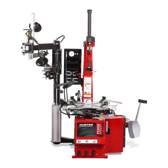
TCX56/57
Tire Changer Family
Operating Instructions
TCX 57
TCX 56
Standard version
Leverless version
©Copyright 2009-2012 Hunter Engineering Company
Table of
Contents
Previous
Page
Next
Page
1
2
3
4
5
Advertisement
Table of Contents
Need help?
Do you have a question about the TCX56 and is the answer not in the manual?
Ask a question
Questions and answers
Related Manuals for Hunter TCX56
Tyre Changers Hunter TCX575 Operation Instructions Manual
Tire changer (48 pages)
Tyre Changers Hunter TCX450 Operation Manual
Tire changer (52 pages)
Tyre Changers Hunter TCX640 Operation Manual
Tire changer (52 pages)
Tyre Changers Hunter TCX500 Operation Manual
Tire changer (52 pages)
Tyre Changers Hunter TCX550 Operation Manual
Tire changer (52 pages)
Tyre Changers Hunter TCX525 Operation Manual
Tire changer (52 pages)
Tyre Changers Hunter TCX3000 Instruction Manual
Hydraulic car tyre changer (152 pages)
Tyre Changers Hunter TCX57 Operating Instructions Manual
Standard version, leverless version (68 pages)
Tyre Changers Hunter TCX50 Operation Manual
(52 pages)
Tyre Changers Hunter TCX50H Series Operation Manual
(55 pages)
Tyre Changers Hunter TCX 58 Operating Instructions Manual
(84 pages)
Tyre Changers Hunter TCX 59 Operating Instructions Manual
(84 pages)
Tyre Changers Hunter TCX50C Operation Manual
(50 pages)
Tyre Changers Hunter TC39 Series Operation Instructions Manual
(37 pages)
Tyre Changers Hunter Revolution Series Operation Instructions Manual
(12 pages)
Tyre Changers Hunter TC33 Series Operation Instructions Manual
(55 pages)
This manual is also suitable for:
Tcx57
Table of Contents
Print
Rename the bookmark
Delete bookmark?
Delete from my manuals?
Login
Sign In
OR
Sign in with Facebook
Sign in with Google
Upload manual
Upload from disk
Upload from URL


Need help?
Do you have a question about the TCX56 and is the answer not in the manual?
Questions and answers