
Related Manuals for Hunter TCX50H Series


Summary of Contents for Hunter TCX50H Series
- Page 1 4-122607 - 07/17 TCX50H Tire Changer Family Operations Manual ©Copyright 2021 Hunter Engineering Company...
- Page 3 If you have any questions concerning the proper use or maintenance of your Tire Changer, please call your authorized Hunter Engineering Company representative.. You can also contact Hunter Engineering Company at Tel: 800-448-6848 or 314-731-3020, Fax. 314-731-1776 or use Sincerely,...
- Page 4 OWNER INFORMATION Owner Name _____________________________________________________________________ Owner Address ___________________________________________________________________ Model Number ____________________________________________________________________ Serial Number ____________________________________________________________________ Date Purchased ___________________________________________________________________ Date Installed ____________________________________________________________________ Service and Parts Representative _____________________________________________________ Phone Number ___________________________________________________________________ Sales Representative ______________________________________________________________ Phone Number ___________________________________________________________________ Training Checklist Safety Precautions Trained Declined Warning and Caution Labels Pinch Points and Other Potential Hazards Safe Operating Procedures...
- Page 5 Mounting Trained Declined Standard Wheels Mounting of Stiff, Low Profile Tires Reverse Drop Center Wheels Proper Bead Lubrication for Mounting Protection Inflation Trained Declined Safety Precautions Lubrication and Removal of Valve Core Bead Sealing and Seating Individuals and Dates Trained ___________________________________ ___________________________________ ___________________________________...
-
Page 6: Table Of Contents
Contents 1. Getting Started..................8 1.1 Introduction ..................... 8 1.1.a – PURPOSE OF THE MANUAL ............8 1.2 For Your Safety ....................9 Hazard Definitions ................... 9 1.3 General Warnings and Instructions .............. 9 Electrical Indications ................13 Specific Precautions/Power Source ............14 Equipment installation and service ............ - Page 7 3.3 Advanced Mounting Procedures ..............33 3.4 Mount/Demount Head Assembly ..............33 Checking Mount/Demount Head Calibration For Steel Heads ....33 Set Position of Steel Mount/Demount Head on Hex Shaft ....33 For Tilting Plastic Heads ............... 35 Set Position of Plastic Mount/Demount Head on Hex Shaft ....35 Adjust the Offset of Lock Mechanism –...
-
Page 8: Getting Started
In addition, so we can contact our customers with any necessary safety information, please ask the new owner to complete and return to Hunter the change of ownership form attached to the last page of this manual. Alternately, the new owner can send an email to newuser@hunter.com. -
Page 9: For Your Safety
1.2 For Your Safety Hazard Definitions These symbols identify situations that could be detrimental to your safety and/or cause equipment damage. DANGER DANGER: Indicates an imminently hazardous situation which, if not avoided, will result in death or serious injury. WARNING WARNING: Indicates a potentially hazardous situation which, if not avoided, could result in death or serious injury. - Page 10 WARNING Avoid Personal Injury. Carefully read, understand and follow the warnings and instructions given in this manual. This manual is an essential part of the product. Keep it with the machine in a safe place for future reference. 2. Overinflated tires can explode, producing hazardous flying debris that may result in an accident.
- Page 11 22. This machine may only be used, maintained or repaired by properly trained employees of your company. Repairs should only be performed by qualified personnel. Your Hunter service representative is the most qualified person. The employer is responsible for determining if an employee is qualified to safely make any repairs to the machine should repair be attempted by users.
- Page 12 DECAL PLACEMENT HUNTER ENGINEERING COMPANY 11250 HUNTER DRIVE BRIDGETON, MISSOURI 63044 Model TCX500E SERIES MADE IN ITALY Code ANNO DI COSTRUZIONE/ XX/XX ac MANUFACTURED 20XX XX/XX 0-11XXXXXX/XX Serial N. bar/psi /XX-XX Port.max IIAXXXXXX Operation Instructions for TCX50H Tire Charger...
-
Page 13: Electrical Indications
Part Number Description RP11-4-123655 DECAL-PEDAL OPERATION RP11-4-402030 DECAL-INFLATRON PEDAL OPERATION 128-1484-2 DECAL-HUNTER LOGO TCX50 128-1485-2 DECAL-HUNTER LOGO TCX51 128-1486-2 DECAL-HUNTER LOGO TCX53 RP11-4-402021 DECAL-MANUAL TIRE BLEED VALVE RP11-4-115244 DECAL-DANGER OPERATION RP11-4-115243 DECAL-WARNING OPERATION RP11-4-402027 DECAL-MAXIMUM INLET PRESSURE RP11-3020842 DECAL-TABLE ROTATION... -
Page 14: Specific Precautions/Power Source
Use only a power cord that is in good condition. Equipment installation and service A factory-authorized representative should perform installation. This equipment contains no user serviceable parts. All repairs must be referred to a qualified Hunter Service Representative Equipment specification Electrical Voltage:... -
Page 15: Air Pressures
Risk of electrical shock. 1.3.b. Air Pressures The machine is equipped with an internal pressure limiting valve to minimize the risk of over inflating the tire. DANGER • EXPLOSION HAZARD • Never exceed tire pressure recommended by tire manufacturer. Never mismatch tire size and rim size. -
Page 16: Employee Training
1.6 Employee Training 1. The employer is obligated to provide a program to train all employees who service rim wheels in the hazards involved in servicing those rim wheels and the safety procedures to be followed. Service or servicing means the mounting and demounting of rim wheels, and related activities such as inflating, deflating, installing, removing and handling. -
Page 17: During Use
1.8 During Use In the event you hear any strange noise or feel unusual vibrations, if a component system is not operating properly or if there is anything unusual at all, stop using the machine immediately. • Identify the cause and take any necessary remedial action. •... -
Page 18: Tire Bead Breaker Shovel Control
1.11 Tire Bead Breaker Shovel control WARNING Keep arms and legs from between the bead breaker arm and the side of the housing. CRUSH HAZARD CRUSH HAZARD EXPLOSION HAZARD 4-402023 Press the “In” button to close bead breaker arm and loosen bead (red arrow). -
Page 19: Air Inflation Pedal
1.13 Air Inflation Pedal On the left side of the base, the air inflation pedal operates the two-stage air inflation system. Refer to illustrations on page 27. The pedal controls the air going to the inflation hose and the air inflation jets. DANGER •... -
Page 20: Mount / Demount Head
1.16 Mount / Demount Head WARNING • MOVING PARTS PRESENT. MOVING PARTS CAN CUT AND CRUSH. • Keep hands away from moving parts. • Crush may cause injury. The mount/demount head is suspended from the column above the turntable. The head has a mounting and demounting lip that is designed to install or remove the bead of tire as the wheel is rotated clockwise. -
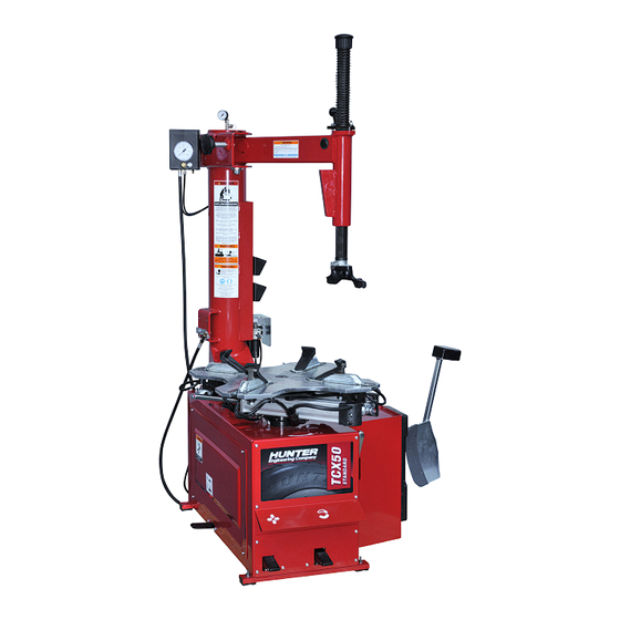
Page 21: Equipment Components
1.17 Equipment Components PRESSURE RELIEF COLUMN STOP VALVE HEAD POSITION SCREW LOCK PRESSURE GUAGE AIR RELEASE BUTTON OILER/ REGULATOR STANDARD MOUNT/ DEMOUNT HEAD MOUNTING INFLATION PASTE HOSE CLAMP AND AIR SHOVEL BLADE JET (4 PLACES) POSITION ADJUSTMENT PIN TURNTABLE BEAD BREAKERARM AND SHOVEL AIR INFLATION PEDAL... -
Page 22: Basic Procedures
2. Basic Procedures 2.1 Bead Breaking CRUSH HAZARD CRUSH HAZARD EXPLOSION HAZARD 4-402023 WARNING All air pressure inside the tire must be removed before proceeding. Never attempt to break the bead until all air is removed from the tire. Failure to remove all air from tire may result in injury to operator, or damage to equipment, tire, or wheel. -
Page 23: Placing Wheel On Tire Changer
Release the “In” button to disengage the bead-breaker arm and press the “Out” button to allow the bead breaker arm to open. If the bead has not completely loosened, rotate the wheel and repeat the bead breaking procedure at a different area on the tire. - Page 24 NOTICE Always verify that all four clamps are on the rim before applying pressure to prevent possible damage to the rim. Plastic jaw covers may be used to help maintain rim protection when clamping externally. Plastic covers also be used to prevent wheel slip. Plastic jaw covers may be replaced periodically when worn by ordering kit RP11-8-11100358 which contains 2 sets of plastic covers.
-
Page 25: Demounting Standard Tire From Rim
2.3 Demounting Standard Tire from Rim Standard Mount / Demount Head NOTICE Clean the mount/demount head to remove dirt and debris before demounting the tire from the rim. Press the wheel rotation pedal until the valve location is in the one o’clock position. Position the mount/demount head against the outer edge of the upper rim lip. - Page 26 Press the wheel rotation pedal to rotate the wheel clockwise. Remove the bead lever tool from the tire when it easily slides out, approximately after a quarter rotation of the wheel. Continue to press the wheel rotation pedal to rotate the wheel clockwise until the entire bead is lifted from the rim.
-
Page 27: Tire Inflation
2.4 Tire Inflation DANGER • EXPLOSION HAZARD • Never exceed tire pressure recommended by tire manufacturer. Never mismatch tire size and rim size. • Avoid personal injury or death. Verify that both upper and lower tire beads and rim bead seat have been properly lubricated with an approved mounting paste. -
Page 28: Special Procedure
WARNING An exploding tire and rim may be propelled upward and outward with enough force to cause serious injury or death. Do not mount any tire unless the tire size (molded into the sidewall) matches the rim size (stamped into the rim) exactly or if the rim or tire are defective or damaged. This tire changer is not a safety device and will not restrain exploding tires and rims. - Page 29 AIR-JET FROM HERE NOTICE To increase the effectiveness of the inflation jets, always liberally lubricate beads and raise the lower bead while activating inflation jets. Step down partially on the pedal to inflate tire and seal beads with inflation hose. Frequently stop to check bead seating pressure on gauge.
-
Page 30: Removal Of Wheel From Tire Changer
2.5 Removal of Wheel from Tire Changer Lift the clamping pedal to release the rim from the clamping device. 2.6 Optional Clamping Jaw Extensions The clamping jaw extension / reducers add 4 inches (102 mm) of exterior clamping OR reduce external clamping by 5 inches (127 mm). JAW ADAPTORS IN EXTENSION JAW ADAPTORS IN REDUCER CONFIGURATION ON 26”... -
Page 31: Advanced Procedures
3. Advanced Procedures The capabilities of the TCX50H tire changer family allow the user to utilize numerous advanced procedures on a variety of rims and tires. For the operator to take advantage of these features, this section explains in detail what additional steps can be taken. 3.1 Advanced Bead Breaking Procedures Bead Breaking “AH”... -
Page 32: Advanced Demounting Procedures
Swing the bead breaker arm toward the tire and position the blade one to two inches from the edge of the rim on the sidewall of the tire. Press the “in” button on the bead-breaker control handle. The bead breaker arm will be pulled toward the tire changer to break the bead. Press the “out”... -
Page 33: Advanced Mounting Procedures
3.3 Advanced Mounting Procedures Always use this “checklist” as a guide when mounting tires to ensure proper service. There are four basic steps when mounting a tire to a rim: • Position the bead on top of the rear lip of mount/demount head. •... - Page 34 HEX SHAFT SET SCREWS ADJUSTMENT HEAD BOLTS RETAINING BOLT 4- Position the tool head manually against the edge of the rim so that both sides of the tool head are resting on it. 5- Tighten the set screws in alternation to maintain 5/64 in. horizontal gap at leading and trailing edge of the mount head.
-
Page 35: For Tilting Plastic Heads
Figure below is a summary of the desired end result. 17-18” For Tilting Plastic Heads Figure below is a summary of the desired end result. The head will adjust itself to each rim diameter, due to its tilting feature. TILTING Set Position of Plastic Mount/Demount Head on Hex Shaft 1- Fit the head on the hexagonal shaft. -
Page 36: Adjust The Offset Of Lock Mechanism - Steel And Plastic Heads
Adjust the Offset of Lock Mechanism – Steel and Plastic Heads 1- Again, position the mount/demount head on the outer edge of upper rip lip and lock in this position. 2- Use gauges to measure distances between head and the top of the rim. Measure at inserts on steel head. -
Page 37: Tcx51H Operational Supplement
4. TCX51H Operational Supplement BP Arm Operation 4.1 General Information This chapter contains information for the correct use of the optional BP Bead Press Arm. The BP Bead Press Arm has been designed as an accessory to help the operator mount the tire on the rim, or to demount the tire from the rim. -
Page 38: Operation
4.3 Operation The BP Bead Press Arm has been designed to facilitate the operations of wheel locking and mounting/demounting the tire on or from the rim. These operations, especially with low-profile, very wide tires, or very hard beads can be very difficult. Clamping the Wheel Break the beads of the tire following the instructions in Section 2.1, Bead Breaking, page If you plan to clamp the wheel from the inside, follow the instructions in Section 2.2, Clamping... -
Page 39: Demounting
Demounting If the outer bead of the tire has “re-seated”, or needs additional lubrication, the bead loosening procedure can be repeated with the BP Bead Press Arm rather than the side shovel. The BP Bead Press Arm can be used when removing the tire from the rim. 1- Position the mount/demount head on the tire and rim. -
Page 40: Using The Bead Press Head Hook To Lift The Tire
Using the Bead Press Head Hook to Lift the Tire Use the hook on the bead press head to help lift the tire during demount. With upper bead demounted, use the bead lever and position the bead press head hook under the upper bead on the opposite side of the tire. - Page 41 2- Rotate clockwise . The Bead Press Arm head will revolve with the tire and keep the bead in the drop center. The second bead will thus be mounted on the rim without any effort or danger to the operator and without damaging the tire. 3- If equipped use the optional clamp to assist mounting when ever more difficult tires are being serviced.
-
Page 42: Tcx53H Operational Supplement
5. TCX53H Operational Supplement Bead Press System Operation 5.1 General Information This chapter contains information for the correct use of the optional Bead Press System (BPS). The BPS has been designed as an accessory to help the operator mount the tire on the rim, or to demount the tire from the rim. -
Page 43: Operation
5.3 Operation The Bead Press System has been designed to facilitate the operations of wheel locking and mounting/demounting the tire on or from the rim. These operations, especially with low-profile, very wide tires, or very hard beads can be very difficult. Clamping the Wheel Break the beads of the tire following the instructions in Section 2.1, Bead Breaking, page If you plan to clamp the wheel from the inside, follow the instructions in Section 2.2, Clamping... -
Page 44: Demounting The Outer Bead
3. Move the control lever downwards until the roller presses on the tire and the bead moves a few millimeters away from the rim, then rotate the turntable clockwise. The swivel arm will turn with the tire until it comes against the end travel stop. At this point the roller will begin to loosen the top bead on the tire. -
Page 45: Breaking The Inner Bead
7. Operate the BPS control lever to lower the arm and put pressure on the tire until the bead is in the drop center of the rim. This prevents the bead from being excessively taut and allows it to rise more easily on the toolhead. 8. -
Page 46: Demounting The Inner Bead
Demounting the Inner Bead 1. If the wheel has a sensor, rotate the table top until it lines up with the toolhead. 2. Position the tire lifting disc under the inner bead, then, using the BPS control lever, lift the bead until it is in the middle of the drop center. -
Page 47: Special Procedure For Run Flat Wheels / Low Profile
Special Procedure for Run Flat Wheels / Low Profile With the second roller arm, the Bead Press System can correctly work on Run Flat wheels. NOTICE The majority of Run Flat wheels are equipped with an internal sensor so that the pressure can be measured. -
Page 48: Mounting The Outer Bead
Mounting the Outer Bead 1. If the wheel has an internal sensor, position it directly across from the toolhead. 2. Mount the second roller arm on the BPS. 3. Position both rollers as shown below. 4. Lower the arms until the outer bead is in the drop center and under the hooked section of the toolhead. -
Page 49: Sensor Inspection/Replacement
Sensor Inspection/Replacement If the wheel has an internal sensor, the BPS used with the second roller will allow you to inspect and replace the actual sensor itself without having to remove the tire from the rim. NOTICE Only work on the sensor after having consulted the operation and maintenance manuals of the vehicle and sensor itself. -
Page 50: Maintenance
6. Maintenance 6.1 Maintenance Schedule DANGER • EXPLOSION HAZARD • Never exceed tire pressure recommended by tire manufacturer. Never mismatch tire size and rim size. • Avoid personal injury or death. CRUSH HAZARD CRUSH HAZARD EXPLOSION HAZARD 4-402023 CRUSH HAZARD. Before making any adjustments or carrying out maintenance, disconnect the electricrical and compressed air supplies from the equipment and make sure that all moving parts are suitably immobilized. - Page 51 The components of Hunter Engineering Company products are designed as a single integrated system. To avoid compromises in terms of safety, performance, durability and function, and to prevent voiding of the warranty, do not substitute Hunter Engineering Company components with components manufactured by other companies. Use only ORIGINAL replacement PARTS supplied by Hunter Engineering Company.
-
Page 52: Maintenance And Replacement Parts
Weekly Do not use cleaning solvents to clean pressure regulator/oiler. Refill the pressure regulator/oiler using only Hunter Lubri-Oil, 148-133-2, as needed. Petroleum- based oils should never be used in the oiler and may void all warranties. -
Page 53: Glossary
7. Glossary 7.1 Rim Diagram Operation Instructions for TCX50H Tire Charger... -
Page 54: Illustrations Of Various Rim Designs
7.2 Illustrations of Various Rim Designs Operation Instructions for TCX50H Tire Charger... - Page 55 Hunter Research and Training Center HUNTER TRAINING Hunter operates the most advanced, up-to-date Training Center in the industry today. The courses have been designed to meet the needs of new and experienced technicians who want to increase their mechanical and diagnostic capabilities. The low student-teacher ratio (average 7 to 1) and the emphasis on “hands-on”...
Need help?
Do you have a question about the TCX50H Series and is the answer not in the manual?
Questions and answers