
Related Manuals for Hunter TCX575


Summary of Contents for Hunter TCX575
- Page 1 Form 6097-T, 01-12 Supersedes Form 6097-T, 10-09c TCX575 Tire Changer Operation Instructions ©Copyright 2009-2012 Hunter Engineering Company...
- Page 3 EC Declaration of Conformity We herewith declare, HUNTER ENGINEERING COMPANY 11250 Hunter Drive Bridgeton, Missouri 63044-2391 USA that the following described machine in our delivered version complies with the appropriate basic safety and health requirements based on its design and type, as brought into circulation by us. In case of alteration of the machine, not agreed upon by us, this declaration will lose its validity.
- Page 4 OWNER INFORMATION Model Number ____________________________________________________________________ Serial Number ____________________________________________________________________ Date Installed ____________________________________________________________________ Service and Parts Representative _____________________________________________________ Phone Number ___________________________________________________________________ Sales Representative ______________________________________________________________ Phone Number ___________________________________________________________________ Concept and Procedure Explanation Safety Precautions Trained Declined □ □ Warning and Caution Labels □ □...
- Page 5 Mounting Trained Declined □ □ Standard Wheels □ □ Mounting of Stiff, Low Profile Tires □ □ Proper Bead Lubrication for Mounting Protection □ □ Single/Dual Arm Bead Press System Operation Inflation Trained Declined □ □ Safety Precautions □ □ Lubrication and Removal of Valve Core □...
-
Page 7: Table Of Contents
1.11 Mount / Demount Head ..................... 6 1.12 Equipment Components ..................7 TCX575 Tire Changer Components ..............7 Bead Press System (BPS) Components ............... 8 TCX575 Tire Changer Decal Locations ..............9 2. BASIC PROCEDURES .................. 11 2.1 Bead Breaking ......................11 PowerOut Versions .................... - Page 8 5.1 Rim Diagram ......................37 5.2 Illustrations of Various Rim Designs ..............38...
-
Page 9: Getting Started
The owner of the TCX575 is solely responsible for enforcing safety procedures and arranging technical training. The TCX575 is to be operated only by a qualified trained technician. Maintaining records of personnel trained is solely the responsibility of the owner or management. - Page 10 Misuse of this equipment can cause personal injury and shorten the life of the tire changer. To prevent accidents or damage to the tire changer, use only Hunter recommended procedures and accessories. Wear OSHA approved eye protection while operating the tire changer.
-
Page 11: Control Pedals
Hunter Engineering Company 11250 Hunter Drive Bridgeton, Missouri 63044 800-448-6848 314-731-3020 Internet address: www.hunter.com 1.3 Control Pedals Control pedals on the TCX575 tire changer are configured as shown below: PowerOut Version NOTE: SHOVEL CONTROLLED COLUMN TABLE CLAMP ROTATION... -
Page 12: Wheel Rotation Pedal
Press the "In" button to close bead breaker arm and loosen bead. Press the "Out" button to allow the bead breaker arm to open. 4 1. Getting Started Operation Instructions for TCX575 Tire Changer... -
Page 13: Wheel Clamping Pedal
Step down partially on the pedal to inflate tires through inflation hose. Step down completely on the pedal to activate the air inflator jets to seal tire beads. 1. Getting Started 5 Operation Instructions for TCX575 Tire Changer... -
Page 14: Inflator And Pressure Limiter
The bead of tire is placed on top of mounting lip during mounting. The bead of tire is placed on top of demounting lip during demounting. The automatic lever is placed inside the tire to ease the demounting process. 6 1. Getting Started Operation Instructions for TCX575 Tire Changer... -
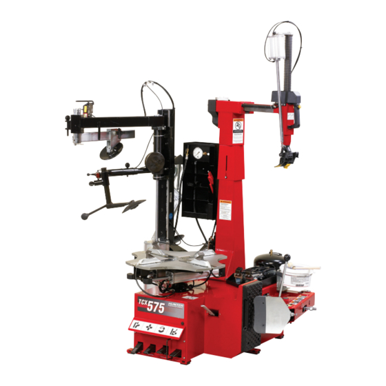
Page 15: Equipment Components
OILER/REGULATOR BEAD TURNTABLE LOOSENING ARM AND SHOVEL TABLE HEIGHT ADJUSTMENT KNOB (not shown) AIR INFLATION PEDAL TIRE BEAD COLUMN LOOSENING ROTATION PEDAL WHEEL PEDAL WHEEL ROTATION CLAMPING PEDAL PEDAL 1. Getting Started 7 Operation Instructions for TCX575 Tire Changer... -
Page 16: Bead Press System (Bps) Components
2. Rim Presser cone 7. Sliding locking lever 3. Control Lever 8. Demounting arm lock 4. Bead presser roller 9. Arm end of travel pin 5. Match mounting lock 8 1. Getting Started Operation Instructions for TCX575 Tire Changer... -
Page 17: Tcx575 Tire Changer Decal Locations
RP11-4-402018 DECAL-HUNTER BEAD PRESS SYSTEM RP11-3013640 DECAL-BPS POSITIONING RP11-4-402021 DECAL-MANUAL TIRE BLEED VALVE RP11-4-402038 DECAL-VERTICAL COLUMN LOCK BUTTON OPERATION RP11-4-402028 DECAL-WARNING PRESSUREL IMITATIONS RP11-3016548 DECAL-BPS LOCK RP11-4-402022 DECAL-WARNING OPERATION 1. Getting Started 9 Operation Instructions for TCX575 Tire Changer... - Page 18 10 1. Getting Started Operation Instructions for TCX575 Tire Changer...
-
Page 19: Basic Procedures
Press the "Out" button to allow the bead breaker arm to open and position the wheel against the side of the tire changer, between the bead-breaker arm and the housing. 2. Basic Procedures 11 Operation Instructions for TCX575 Tire Changer... -
Page 20: Non-Powerout Versions
If the bead has not completely loosened, rotate the wheel and repeat the bead breaking procedure at a different area on the tire. Turn the wheel and break the opposite bead using the same procedure. 12 2. Basic Procedures Operation Instructions for TCX575 Tire Changer... -
Page 21: Placing Wheel On Tire Changer
Slide the mount/demount head in or out along the upper rail and lower the head into position. Push the button on handle to lock head into position. The mount / demount head will automatically build in the proper spacing. 2. Basic Procedures 13 Operation Instructions for TCX575 Tire Changer... - Page 22 If the automatic lever does not completely seat under the upper bead, continue to rotate until it does. Press the wheel rotation pedal until the valve location is in the one o'clock position. 14 2. Basic Procedures Operation Instructions for TCX575 Tire Changer...
-
Page 23: Difficult Tires
On difficult tires where the automatic bead lever does not have sufficient power to pull the tire over, use the Bead Press System (BPS) on the opposite side of the tire and press down. TOOL HEAD BPS DISC 2. Basic Procedures 15 Operation Instructions for TCX575 Tire Changer... - Page 24 BPS disc and push down to create a gap between the tire and the rim edge (A), then insert the automatic bead lever (B). PUSH DOWN AT THIS POINT INSERT AUTOMATIC BEAD LEVER 16 2. Basic Procedures Operation Instructions for TCX575 Tire Changer...
-
Page 25: Precautionary Notes
NOTE: Alternatively, you may lift the tire up first, lower the automatic lever, lift the tire into place and then lower the automatic lever beneath the bottom bead. 2. Basic Procedures 17 Operation Instructions for TCX575 Tire Changer... -
Page 26: Bottom Bead Demounting With Disc
Return the tool head to the “resting” position. Lower and align the lower disc to touch the bottom of the rim edge. 18 2. Basic Procedures Operation Instructions for TCX575 Tire Changer... - Page 27 This will create a gap between the rim edge and the tire. With the tire in position, press the wheel rotation pedal to rotate the wheel clockwise and demount the bottom bead. 2. Basic Procedures 19 Operation Instructions for TCX575 Tire Changer...
-
Page 28: Difficult Tires
Press the wheel rotation pedal until the valve location is in the one o'clock position. Position the mount/demount head against the outer edge of the upper rim lip. 20 2. Basic Procedures Operation Instructions for TCX575 Tire Changer... - Page 29 Remove the bead lever tool from the tire when it easily slides out, approximately after a quarter rotation of the wheel. Continue to press the wheel rotation pedal to rotate the wheel clockwise until the entire bead is lifted from the rim. 2. Basic Procedures 21 Operation Instructions for TCX575 Tire Changer...
-
Page 30: Mounting Standard Tire To Rim
Mount a standard tire to rim as follows: Lubricate inside and outside of both beads of the tire to be mounted with supplied mounting paste. 22 2. Basic Procedures Operation Instructions for TCX575 Tire Changer... - Page 31 When mounting the top bead, it is important to get the correct positioning of the tire on the mount / demount head. MOUNT HEAD CORRECTLY PLACED MOUNT HEAD INCORRECTLY PLACED 2. Basic Procedures 23 Operation Instructions for TCX575 Tire Changer...
- Page 32 With the tire in position, press the wheel rotation pedal to rotate the wheel clockwise and mount the top bead. 24 2. Basic Procedures Operation Instructions for TCX575 Tire Changer...
-
Page 33: Match Mounting
Position the lower disc at the rim edge on the bottom of the assembly and lock it in place. Raise the lower disc such that the pitch between the upper and discs is approximately equal. UPPER DISC LOWER DISC 2. Basic Procedures 25 Operation Instructions for TCX575 Tire Changer... -
Page 34: Tire Inflation
If tire is over-inflated, air may be removed from the tire by pressing the brass manual air release button located below the air pressure gauge. 26 2. Basic Procedures Operation Instructions for TCX575 Tire Changer... -
Page 35: Removal Of Wheel From Tire Changer
Disconnect inflation hose from valve stem. 2.7 Removal of Wheel from Tire Changer Lift the clamping pedal to release the rim from the clamping device. 2. Basic Procedures 27 Operation Instructions for TCX575 Tire Changer... -
Page 36: Advanced Procedures
3. Advanced Procedures The capabilities of the TCX575 allows the user to utilize numerous advanced procedures on a variety of rims and tires. For the operator to take advantage of these features, this section explains in detail what additional steps can be taken. - Page 37 Do not attempt to use the BPS Device for bead breaking. It is only to be used to loosen beads that have already been loosened with the side shovel. 3. Advanced Procedures 29 Operation Instructions for TCX575 Tire Changer...
-
Page 39: Maintenance, Calibration And Replacement Parts
Do not hose down or power wash electric tire changers. CAUTION: Proper care and maintenance are necessary to ensure that the TCX575 operates properly. Proper care will also ensure that rims and tires are not damaged during the mount/demount process. -
Page 40: Mount/Demount Head Assembly
3. Position the tool head manually against the edge of the rim so that both sides of the tool head are resting on it. Keep the tool head in position without engaging the head position lock. 32 4. Maintenance, Calibration and Replacement Parts Operation Instructions for TCX575 Tire Changer... -
Page 41: Horizontal Adjustment Of The Tool Head
TOOL HEAD SHOULD TOUCH RIM AT THIS POINT TOOL HEAD SHOULD BE FLUSH WITH EDGE OF RIM 4. Maintenance, Calibration and Replacement Parts 33 Operation Instructions for TCX575 Tire Changer... -
Page 42: Adjusting The Vertical Gap
Re-check gap. Adjusting the Horizontal Gap 1. Release the tool head, then reposition it on the rim and lock it in place with the head position lock. 34 4. Maintenance, Calibration and Replacement Parts Operation Instructions for TCX575 Tire Changer... - Page 43 The distance should be between .08 and .16 inch. If not, repeat the calibration process. .08 - .16 inch GAP 4. Maintenance, Calibration and Replacement Parts 35 Operation Instructions for TCX575 Tire Changer...
-
Page 44: Replacement Parts
Bead Lever Protector Sleeve (Std) (4) RP11-8-11400098 Jaw Protection Kit (2 sets - 8 covers) RP11-8-11400085 Mount/demount Protector Kit consisting RP11-8-11400293 10 demounting protectors 5 mounting protectors 15 protector screws 36 4. Maintenance, Calibration and Replacement Parts Operation Instructions for TCX575 Tire Changer... -
Page 45: Glossary
5.1 Rim Diagram RIM WIDTH OUTBOARD INBOARD OUTBOARD BEAD SEAT FLANGE FLANGE INBOARD BEAD SEAT RIM CENTERLINE POSITIVE OFFSET NEGATIVE OFFSET CENTERLINE REAR SPACING DROP CENTER INBOARD OUTBOARD SAFETY HUMP SAFETY HUMP 5. Glossary 37 Operation Instructions for TCX575 Tire Changer... - Page 46 REVERSE DROP CENTER CONICAL OUTBOARD MULTIPLE STROKES REQUIRED FOR REMOVAL OF LOWER BEAD INBOARD LONG DROP CENTER CYLINDRICAL OUTBOARD RIM DISASSEMBLY REQUIRED - DO NOT USE ON TCX550 INBOARD NO DROP CENTER 38 5. Glossary Operation Instructions for TCX575 Tire Changer...
- Page 48 Hunter Research and Training Center HUNTER TRAINING Hunter operates the most advanced, up-to-date Training Center in the industry today. The courses have been designed to meet the needs of new and experienced technicians who want to increase their mechanical and diagnostic capabilities. The low student-teacher ratio (average 7 to 1) and the emphasis on “hands-on”...
Need help?
Do you have a question about the TCX575 and is the answer not in the manual?
Questions and answers