
Related Manuals for Hunter TC39 Series


Summary of Contents for Hunter TC39 Series
- Page 1 OPERATION INSTRUCTIONS 7108-M010-3_H Rev. 3 (02/2020) TC39 Series Tire Changer Copyright 2018 Hunter Engineering Company...
- Page 2 OWNER INFORMATION Model Number _____________________________________________________________________ Serial Number _____________________________________________________________________ Date Installed ______________________________________________________________________ Service and Parts Representative ______________________________________________________ Phone Number _____________________________________________________________________ Sales Representative ________________________________________________________________ Phone Number _____________________________________________________________________ Concept and Procedure Explanation Safety Precautions Trained Declined Warning and Caution Labels Bead Roller Maintenance and Performance Checks Trained Declined Air Pressure Check...
- Page 3 Individuals and Date Trained ___________________________________ ___________________________________ ___________________________________ ___________________________________ ___________________________________ ___________________________________ ___________________________________ ___________________________________ ___________________________________ ___________________________________ ___________________________________ ___________________________________ ___________________________________ ___________________________________ ___________________________________ ___________________________________ ___________________________________ ___________________________________ ___________________________________ ___________________________________ ___________________________________ ___________________________________ ___________________________________ ___________________________________ ___________________________________ ___________________________________...
-
Page 4: Table Of Contents
3. MAINTENANCE AND CALIBRATION ............29 3.1 Maintenance Schedule ..................29 3.2 Maintenance Replacement Parts ................. 30 3.3 Checking the Bead Rollers ................... 31 3.4 Tool Head Adjustment ..................32 Contents • • • • i TC39 Series Changer Operation Instructions... -
Page 5: Getting Started
DANGER: Immediate hazards, which will result in severe personal injury or death. These symbols identify situations that could be detrimental to your safety and/or cause equipment damage. Getting Started • • • • 1 TC39 Series Changer Operation Instructions... -
Page 6: Important Safety Instructions
Read and understand all instructions before operating this machine. Misuse of this equipment can cause personal injury and shorten the life of the TC. To prevent accidents or damage to the TC, use only Hunter recommended procedures and accessories. Wear OSHA approved eye protection while operating the TC. -
Page 7: Decal Placement
Service and maintain machine regularly as outlined in “Maintenance and Calibration,” on page 29. For further information contact: Hunter Engineering Company 11250 Hunter Drive http://www.hunter.com Bridgeton, Missouri 63044 (314) 731-3020 Decal Placement Getting Started • • • • 3 TC39 Series Changer Operation Instructions... -
Page 8: Electrical
To prevent the possibility of electrical shock injury or damage to the equipment when servicing the TC, power must be disconnected by removing the power cord from the electrical power outlet. 4 • • • • Getting Started TC39 Series Changer Operation Instructions... -
Page 9: Specific Precautions/Power Source
CCW – 7rpm Torque: 867 ft-lbs Max. Tire Diameter: 46 in. Max Bead Roller Opening Width: 15 in. Diameter Range: 10-26 in. Bead Roller Power; Each Roller: 2645 lbs. Getting Started • • • • 5 TC39 Series Changer Operation Instructions... -
Page 10: Safety Summary
Step down on the pedal to rotate the wheel clockwise (variable speed). Lift the pedal to rotate the wheel counterclockwise (fixed speed). CAUTION: Keep hands clear of wheel, tire, and rollers during bead loosening. 6 • • • • Getting Started TC39 Series Changer Operation Instructions... -
Page 11: Air Inflation Pedal
Position 1 (rest position) stops the operated bead breaker roller in its current position; Position 2 (held position) lowers the upper bead breaker roller or lifts the lower bead breaker roller; Getting Started • • • • 7 TC39 Series Changer Operation Instructions... - Page 12 Tool command unit consists of two push buttons. The upper push button controls the rising, while the lower push button controls tool descent. 8 • • • • Getting Started TC39 Series Changer Operation Instructions...
-
Page 13: Equipment Components
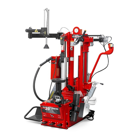
1.10 Equipment Components Getting Started • • • • 9 TC39 Series Changer Operation Instructions... -
Page 14: Tool Head
Demounting If the tool head breaks near the middle the user was rotating the wheel and tire assembly while pressing the “Tool Head Raise” button. 10 • • • • Getting Started TC39 Series Changer Operation Instructions... - Page 15 Ensure the bead is completely in the drop center on wheels where the drop center is far from the bead seat. BEAD NOT IN DROP CENTER BEAD FULLY IN DROP CENTER Getting Started • • • • 11 TC39 Series Changer Operation Instructions...
-
Page 16: Basic Procedures
If the bead has not completely loosened, rotate the wheel and repeat the bead loosening procedure at a different area on the tire. Turn the wheel and loosen the opposite bead using the same procedure. 12 • • • • Basic Procedures TC39 Series Changer Operation Instructions... -
Page 17: Placing Wheel On Tc
Use the lowest height for most reverse drop-center wheels. To adjust center support height, pull the knob outwards on center support and raise or lower center support table to desired height. Basic Procedures • • • • 13 TC39 Series Changer Operation Instructions... -
Page 18: Standard And High Offset Wheels
Place the wheel, face up, on the center support. Ensure the anti-rotation pin enters a lug hole in the wheel. Insert wheel clamp, press down and twist clockwise 1/4 turn to lock into center support. 14 • • • • Basic Procedures TC39 Series Changer Operation Instructions... -
Page 19: Reverse Drop Center Wheels
Adjust center support position to appropriate settings for the tire and wheel combination to be serviced. This is typically the lowest setting. Place anti-rotation pin protector and wheel protector pad on center support Anti/Rotation Pin with Extensions Basic Procedures • • • • 15 TC39 Series Changer Operation Instructions... - Page 20 Insert wheel clamp, press down and twist clockwise 1/4 turn to lock into center support. The clamping shaft is equipped with a quick clamp cone to speed clamping. Simply activate the Quick Clamp, drop the cone into place then hand tighten. 16 • • • • Basic Procedures TC39 Series Changer Operation Instructions...
-
Page 21: Large Pilot Hole Wheels
Place wheel on center support ensuring anti-rotation pin inserts one lug hole. Place adapter cone on the wheel. Insert wheel clamp, press down and twist clockwise 1/4 turn to lock into center support. Basic Procedures • • • • 17 TC39 Series Changer Operation Instructions... -
Page 22: Bead Loosening
CAUTION: Never place hands near the rollers while applying force and rotating tire. Hands could be pulled between the roller and tire causing injury. Remove upper roller. 18 • • • • Basic Procedures TC39 Series Changer Operation Instructions... -
Page 23: Demounting Tires From Rim
Refer to “Demounting” on page 10 for more details. With the upper roller pressing down on the tire insert the mount / demount head in between the bead and the rim. Remove the upper roller. Basic Procedures • • • • 19 TC39 Series Changer Operation Instructions... - Page 24 Raise the lower roller until the lower bead is slightly above the rim. Rotate wheel until the entire bead is lifted from the rim. Remove tire from rim. 20 • • • • Basic Procedures TC39 Series Changer Operation Instructions...
-
Page 25: Mounting Tire To Rim
Lower the lower the mount/demount head to cradle the rim. Rotate to mount the lower bead onto the tire. Stop when the lower bead is on the rim. Basic Procedures • • • • 21 TC39 Series Changer Operation Instructions... - Page 26 (B). CAUTION: Improper procedures on the next step may damage tool head. Refer to “Demounting” on page 10 for more details. Rotate clockwise to mount the tire. 22 • • • • Basic Procedures TC39 Series Changer Operation Instructions...
- Page 27 While rotating watch the bead at the mount / demount head. Ensure it is going under the demount hump on the head and not over it. Correct Incorrect Front View Rear View Remove the mount / demount head from the tire. Basic Procedures • • • • 23 TC39 Series Changer Operation Instructions...
- Page 28 Failure to do so may cause the upper bead roller to contact the bead press and cause damage. Best position after use Remove the upper roller from the tire. 24 • • • • Basic Procedures TC39 Series Changer Operation Instructions...
-
Page 29: Mounting Tough, Low Profile Tires
Position the roller of the Plus Device on the tire sidewall at the 2 o’clock position and press the bead into the drop centre. Turn clockwise until the upper bead is mounted. Basic Procedures • • • • 25 TC39 Series Changer Operation Instructions... -
Page 30: Matching/Optimizing Of Tire To Rim
Continue rotating the tire and rim at different speeds until the rim spins inside the tire and the mark on the tire is positioned where needed in reference to the rim. Once matching has occurred, retract arms and inflate. 26 • • • • Basic Procedures TC39 Series Changer Operation Instructions... -
Page 31: Tire Inflation
Press the bead blaster hose on the wheel rim as shown below. Ensure the hose head is pressed in. NOTE: The nozzle should be horizontal for optimal performance. NOZZLE IS HORIZONTAL CORRECT NOZZLE IS NOT NOZZLE IS NOT HORIZONTAL HORIZONTAL INCORRECT INCORRECT Basic Procedures • • • • 27 TC39 Series Changer Operation Instructions... -
Page 32: Removal Of Wheel From Tc
Press down quick clamp and turn counter-clockwise to unlock clamp from center support. Remove wheel clamp. Remove wheel from center support. If applicable, remove anti-rotation pin extensions and wheel protector pad from center support. 28 • • • • Basic Procedures TC39 Series Changer Operation Instructions... -
Page 33: Maintenance And Calibration
Replace worn parts as needed (rubber pads and blocks, rollers, and mount/demount head). Clean all areas that contact rims or tires to prevent possible scratching to rim. Maintenance and Calibration • • • • 29 TC39 Series Changer Operation Instructions... -
Page 34: Maintenance Replacement Parts
Do not use cleaning solvents to clean pressure regulator/oiler. Periodically Refill the pressure regulator/oiler using only Hunter Lubri-oil as needed. Petroleum-based oils should never be used in the oiler and may void all warranties. -
Page 35: Checking The Bead Rollers
Raise the lower bead arm, verify clearance of 1 mm (1/24”) from the rim edge. Adjust rollers as follows: In case of adjustment, disconnect the air supply from the machine to allow the unlock of the necks. Maintenance and Calibration • • • • 31 TC39 Series Changer Operation Instructions... -
Page 36: Tool Head Adjustment
Adjust bolt at top of tool head arm until tool head is approximately perpendicular to wheel. Adjust Here Tool Head Support Tighten jam nut on adjustment bolt. 32 • • • • Maintenance and Calibration TC39 Series Changer Operation Instructions... - Page 37 (6) months. In case of any warranty claim, it will be necessary to contact your local authorized Hunter Service Representative. To have an item considered for warranty, it must be returned to Hunter Engineering Company for inspection and evaluation.
Need help?
Do you have a question about the TC39 Series and is the answer not in the manual?
Questions and answers