
Related Manuals for iDirect Evolution X7


Summary of Contents for iDirect Evolution X7
- Page 1 Evolution X7 Satellite Router Installation, Support, and Maintenance Guide Installation, Support, and Maintenance Guide Evolution X7 Satellite Router Router Products September 30, 2013...
- Page 2 Copyright © 2013 VT iDirect, Inc. All rights reserved. Reproduction in whole or in part without permission is prohibited. Information contained herein is subject to change without notice. The specifications and information regarding the products in this document are subject to change without notice. All statements, information, and recommendations in this document are believed to be accurate, but are presented without warranty of any kind, express, or implied.
- Page 3 Revision History The following table shows all revisions for this document. To determine if this is the latest revision, check the TAC Web site at http://tac.idirect.net. Revision Date Updates September 30, 2013 Initial release (JS) Installation, Support, and Maintenance Guide...
- Page 4 Revision History Installation, Support, and Maintenance Guide Evolution X7 Satellite Router...
-
Page 5: Table Of Contents
4.1 Installation Steps at a Glance ........13 Installation, Support, and Maintenance Guide Evolution X7 Satellite Router... - Page 6 4.2 Tools and Supplies Required for Installation ......15 4.3 Unpacking iDirect Evolution X7 Router Equipment..... 15 4.4 Components Typically Included in an Order .
- Page 7 F.3 Level 2 Reset ..........46 Installation, Support, and Maintenance Guide Evolution X7 Satellite Router...
- Page 8 Figure E-1. DC-DC Power Supply Assembly at a Glance ......42 Installation, Support, and Maintenance Guide viii Evolution X7 Satellite Router...
- Page 9 Table D-2. Ethernet Port Pinouts ................37 Table D-3. RJ-45 to DB-9 Pinouts ................39 Table E-1. X7 Router DC Power Module Connector Parts ..........41 Table E-2. Power Module Power Cable Installation Instructions Detail ......42 Installation, Support, and Maintenance Guide Evolution X7 Satellite Router...
- Page 10 Tables Installation, Support, and Maintenance Guide Evolution X7 Satellite Router...
-
Page 11: About
Intended Audience This manual is intended for use by the VSAT (Very Small Aperture Terminal) equipment installer, System Engineer, and Network Operator responsible for maintaining the iDirect Network. Only qualified service personnel should install the X7 Router. Familiarity with cabling and wiring practices is beneficial. -
Page 12: Document Conventions
Related Documents The following documents are available at http://tac.idirect.net. Consult these documents for information about installing and using iDirect’s satellite network software and equipment. • iDX iBuilder User Guide • iDX iMonitor User Guide •... -
Page 13: Related Training Services
Getting Help iDX Software users guides, installation procedures and guides, an FAQ page, and other documentation that supports iDirect products, are available on the TAC Web site located at: http://tac.idirect.net. To find answers to questions or information, contact the iDirect Technical Assistance Center (TAC) at (703) 648-8151. - Page 14 About Installation, Support, and Maintenance Guide Evolution X7 Satellite Router...
-
Page 15: Introduction
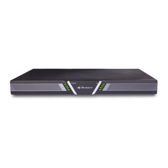
1 Introduction The iDirect Evolution X7 Satellite Router (X7 Router) is a next-generation router supporting DVB-S2/ACM on the outbound and A-TDMA. It uses a compact, rack-mount design, embedded 8-port switch, and variant power supply configurations making it an ideal enterprise class solution. -
Page 16: Power Supply Options
Option 3: 36-76V DC +24 V, +48 V Power Supply Option 3 DC power module for the X7 Router comes with dual selectable +24V/+48V power support for either a +24V or +48V BUC. Installation, Support, and Maintenance Guide Evolution X7 Satellite Router... -
Page 17: Specifications
32˚ to +113˚F (0˚ to +45˚C ) @ 10,000 Feet Storage -40˚ to +176˚F (-40˚ to 80˚C) Temperature Gradient .5˚C per minute ( but < 20˚C per hour) Relative Humidity Operational 90%, non-condensing Storage 5 to 93% Installation, Support, and Maintenance Guide Evolution X7 Satellite Router... -
Page 18: Power Specifications
Option 1, 2, & 3: 24 VDC @ 4.9A (117 W MAX) Option 2 & 3: 48 VDC @ 3.3A (158 W MAX) DC Power @ RX Inputs 13-18 VDC @ 500 mA, voltage is software configurable Installation, Support, and Maintenance Guide Evolution X7 Satellite Router... -
Page 19: Rf Specifications
AC Power Cord Supplied, per country of use DC Input Connector Self-capturing terminal block, 14-16 AWG Efficiency 87% Min RF Specifications The Evolution X7 Satellite Router RF specifications are listed in Table 2-3. Table 2-3. RF Specifications Category Description IF Interface, Impedance Type “F”, Zo = 75 ohms... - Page 20 Spurious & Harmonic Content < -60 dBc, with output @ -20 dBm, (In-band < -32 dBc) Transmitter Muting 50 dB (min); residual carrier < -90 dBm with baseband (BB) and RF muted Installation, Support, and Maintenance Guide Evolution X7 Satellite Router...
-
Page 21: Interfaces
This chapter describes the X7 Router physical interfaces and LEDs, and contains the following sections: • Section 3.1, X7 Router Front LEDs on page 8 • Section 3.3, X7 Router Rear Panel Description on page 10 Installation, Support, and Maintenance Guide Evolution X7 Satellite Router... -
Page 22: X7 Router Front Leds
X7 Front Panel LED Status Descriptions Descriptions for states of LEDs may vary between iDX Software Releases. Check the release specific iDX Satellite Router Installation and Commissioning Guide, Web iSite User Guide, and Installation, Support, and Maintenance Guide Evolution X7 Satellite Router... -
Page 23: Table 3-2. X7 Router Idx 3.2 Led Descriptions
1 second flashing Yellow Downstream carrier configured, demodulator locked to downstream carrier, Network Clock Reference (NCR) not yet locked Green Downstream carrier configured, demodulator and NCR locked to downstream carrier Installation, Support, and Maintenance Guide Evolution X7 Satellite Router... -
Page 24: X7 Router Rear Panel Description
OFF, then router is in Rx (receive) only mode Authentication failed X7 Router Rear Panel Description The X7 Router rear panel is shown in Figure 3-2 and defined in Table 3-3 on page Figure 3-2. Rear Panel Description Installation, Support, and Maintenance Guide Evolution X7 Satellite Router... -
Page 25: Table 3-3. X7 Router Rear Panel Connector And Led Descriptions
LNB Power LEDs: if off, no power to LNB Green - No fault Red - Over-current protection has tripped 13, 15 (future) RX1 IN, RX2 IN Receiver Inputs (F), RX 2 IN is reserved for future use Installation, Support, and Maintenance Guide Evolution X7 Satellite Router... - Page 26 X7 Router Rear Panel Description Installation, Support, and Maintenance Guide Evolution X7 Satellite Router...
-
Page 27: X7 Router Installation
Section 4.1, Installation Steps at a Glance on page 13 • Section 4.2, Tools and Supplies Required for Installation on page 15 • Section 4.3, Unpacking iDirect Evolution X7 Router Equipment on page 15 • Section 4.4, Components Typically Included in an Order on page 15 •... -
Page 28: Installation Checklist
(for routers with DC power supply options, only). 1. Unpack the router according to the unpacking instructions in Section 4.3, Unpacking iDirect Evolution X7 Router Equipment on page 2. Account for all components for the installation. A typical list is given in Section 4.4, Components Typically Included in an Order on page 3. -
Page 29: Tools And Supplies Required For Installation
Remove the tape and any exterior covering from the box lid Save the Evolution X7 Satellite Router shipping boxes after unpacking the system. These boxes will be needed in the event of moving or shipping the system in the future. See Section 5.5,... -
Page 30: X7 Router Mounting
2. Select the appropriate BUC voltage (+24 or +48 VDC) by sliding the BUC voltage selector switch (Table 3-3, X7 Router Rear Panel Connector and LED Descriptions on page Callout #8). 24 VDC BUC voltage selection is the factory setting. Installation, Support, and Maintenance Guide Evolution X7 Satellite Router... -
Page 31: Installing With A 24-48 Vdc Power Supply (Option 3)
5. Set the X7 Router power switch to the ON position (1). 6. Upon powering up, a Level 0 Reset occurs. Reset options are available in Appendix F, X7 Reset on page 45. Installation, Support, and Maintenance Guide Evolution X7 Satellite Router... -
Page 32: Preparing The Pc For Connection To The X7 Router
Refer to the iDX Satellite Router Installation and Commissioning Guide for the release of software installed on the system and for instructions. To download the guide, go to http:\\tac.idirect.net and click Satellite Routers. Installation, Support, and Maintenance Guide Evolution X7 Satellite Router... -
Page 33: Maintenance
(adjust only those controls that are covered by the operating instructions) • If the X7 Router has been dropped or if the chassis has been damaged • When the X7 Router exhibits a distinct change in performance Installation, Support, and Maintenance Guide Evolution X7 Satellite Router... -
Page 34: Maintaining The X7 Router
Table 5-1 describes the most common X7 Router troubleshooting events and actions to take. Consult with the iDirect TAC when considering a reset. Reset functions are described in Section F.1, Level 0 Reset on page 45. Table 5-1. Troubleshooting Events and Actions to Take... -
Page 35: Removing And Replacing The Power Module
The Option 1 Power Module does not support a 48V BUC, and has this barcode: Option 1 Removing and Replacing the Power Module In the event the Power Module must be removed and/or replaced, Table 5-1 describes the steps to take. Installation, Support, and Maintenance Guide Evolution X7 Satellite Router... -
Page 36: Repacking The X7 Router
For warranty service, obtain a Return Material Authorization (RMA) number from the reseller or iDirect prior to shipping. Direct customers of iDirect, may contact the iDirect TAC directly to obtain an RMA number and shipping instructions. Follow the shipping instructions, complete the RMA form, and attach the form to the outside of the shipping box. -
Page 37: Appendix A Acronyms And Abbreviations
BaseBand deciBel isotropic Below-Decks Interface Module deciBel milli-Watt BIST Built-In Self-Test deciBel Watt BITE Built-In Test Equipment Direct Current BUC Part Number Double Data Rate BPSK Binary Phase Shift Keying Installation, Support, and Maintenance Guide Evolution X7 Satellite Router... - Page 38 Loss of Signal Gain over Temperature Line-Replaceable Unit GigaHertz GPIO General-Purpose Input/Output Global Positioning System Mbps Megabits per second Mcps Megachips per second Mobile Earth Station High-Capacity Payload MF-TDMA Multi-Frequency TDMA Installation, Support, and Maintenance Guide Evolution X7 Satellite Router...
- Page 39 Preliminary Design Review TDMA Time Division Multiple Access Phased Locked Loop Terminal Functional ID Phase Shift Keying Terminal Manufacturer ID Power Supply Unit TPCFEC Turbo Product Code FEC Terminal Part Number Installation, Support, and Maintenance Guide Evolution X7 Satellite Router...
- Page 40 Terminal Serial Number Terminal Transmit Control Tx or TX Transmit Universal Data Protocol Underwriters Laboratories Volts Alternating Current Volts Direct Current VSAT Very Small Aperture Terminal Weighted Fair Queuing Wideband Global SATCOM Installation, Support, and Maintenance Guide Evolution X7 Satellite Router...
-
Page 41: Appendix B Safety
Appendix B Safety Follow the safety guidelines in this chapter during installation of the Evolution X7 Satellite Router. These guidelines help to protect the X7 Router from potential damage and help to ensure personal safety. Keep this safety information handy for reference. -
Page 42: Electrical Safety
Follow the warnings and cautions below for personal safety and to protect the equipment from electrical hazards. WARNING: Do not work on the system, or connect or disconnect cables, during periods of lightning activity. Installation, Support, and Maintenance Guide Evolution X7 Satellite Router... -
Page 43: Physical And Environmental Considerations
(including amplifiers) that produce heat. • Accessories Do not place the chassis on any unstable rack, cart, stand, table, or bracket. Mounting of the product must follow the manufacturer’s instructions. Installation, Support, and Maintenance Guide Evolution X7 Satellite Router... - Page 44 Operational and Maintenance Safety Chapter 5 on page 19 provides detailed maintenance information. As the Evolution X7 Satellite Router is used, the following safety guidelines must be observed: • Cables — Never use any other RF cable than what is supplied or recommended by iDirect •...
-
Page 45: Appendix C Tools Needed
Table C-1. Recommended Installation Tools and Equipment Quantity Tool Number 2 Phillips screwdriver F-type Compression Tool RG-6 Coax Stripper Coax / Wire Cutter Length as Needed RG-6 or RG-11 solid copper conductor coax outdoor rated cable Installation, Support, and Maintenance Guide Evolution X7 Satellite Router... - Page 46 Installation, Support, and Maintenance Guide Evolution X7 Satellite Router...
-
Page 47: Appendix D Cable Preparation
In general, specific and detailed instructions are for RG-6 cables and connectors, only. Use high quality coaxial outdoor cable to connect the Evolution X7 Satellite Router to the Outdoor Unit (ODU) equipment. iDirect recommends that a solid copper center conductor,... -
Page 48: Figure D-1. Coax Cable Cutting Technique
D-1. For RG-6, use a two-step Coax Stripper such as the LC-CST 1257 from Paladin Tools. Table D-1. Coax Trim Dimensions Length A Length B Length C (inch (mm)) (inch (mm)) (inch (mm)) RG-6 5/8 (15.9) 1/4 (6.4) 3/8 (9.5) Installation, Support, and Maintenance Guide Evolution X7 Satellite Router... -
Page 49: Figure D-2. Cutting Technique For Removing Foil In The Braid
7. If the conductive foil is burred, then smooth out the burr so that the edge (area where the dielectric material was removed) is smooth and provides a lead-in for the connector mandrel. Installation, Support, and Maintenance Guide Evolution X7 Satellite Router... -
Page 50: Figure D-4. Attaching The Compression Fitting F-Type Connector
9. Finish connecting the cable to the connector with the compression tool connector, such as Holland Compression Tool 1855 as shown in Figure D-5. Figure D-5. Compression fitting F-Type Weatherproof Plug and Tool Installation, Support, and Maintenance Guide Evolution X7 Satellite Router... -
Page 51: D.2 Ethernet Port Pinouts
Ethernet ports (labeled LAN 1-8) of the X7 Router and the pinout order is shown in Figure D-6. Table D-2. Ethernet Port Pinouts RJ-45 Pin Description Installation, Support, and Maintenance Guide Evolution X7 Satellite Router... -
Page 52: Straight Through And Crossover Rj-45 Cables
10-Mbps and 100-Mbps transmission over Unshielded Twisted-Pair (UTP) cables. Use Category-3 or Category-5 UTP cable with RJ-45 connectors to attach the 10/100 Base-T Ethernet LAN ports on the Evolution X7 Satellite Router chassis to the customer provided LAN Hub or switch. -
Page 53: Table D-3. Rj-45 To Db-9 Pinouts
Figure D-8 on page Table D-3. RJ-45 to DB-9 Pinouts Console Port RJ-45 to DB-9 Console RJ-45 Pin Color Code (DTE) Terminal Adapter Device Blue Orange Black Green Yellow Brown Rx-RF-Power White/Grey Not Connected Installation, Support, and Maintenance Guide Evolution X7 Satellite Router... -
Page 54: Figure D-8. Rj-45 To Db-9 Female Dte Adapter
Console Port Connection Figure D-8. RJ-45 to DB-9 Female DTE Adapter Installation, Support, and Maintenance Guide Evolution X7 Satellite Router... -
Page 55: Appendix E Dc Power Supply Installation
Terminal block plug Included in kit, P/N Phoenix 1779848 Cable Entry Housing Cable Entry Housing Strain Strain Relief and Relief and Cable Tie, included Cable Tie in kit, P/N 1803947, and cable Installation, Support, and Maintenance Guide Evolution X7 Satellite Router... -
Page 56: Figure E-1. Dc-Dc Power Supply Assembly At A Glance
DC terminal block plug. Fasten the three screws securely. Do not over-tighten. Insert the cable tie through one of the holes in the right half of the strain relief clip. Installation, Support, and Maintenance Guide Evolution X7 Satellite Router... - Page 57 2. Insert the finished terminal block plug, with the cable entry housing, into the terminal block header in the power supply. Installation, Support, and Maintenance Guide Evolution X7 Satellite Router...
- Page 58 Installation, Support, and Maintenance Guide Evolution X7 Satellite Router...
-
Page 59: Appendix F X7 Reset
Appendix F X7 Reset The X7 Router has three types of reset functions: Level 0, Level 1, and Level 2. Each type has a different effect on the router. Contact the iDirect TAC center for more information. Level 0 Reset Level 0 reset provides a basic reset function. -
Page 60: Level 2 Reset
Recovery: none - reload software, options file, configuration • Router rear LEDs: BUC PWR LED (see callout #9, Table 3-3 on page 11) will turn solid green when the reset button is held for greater than 15 seconds Installation, Support, and Maintenance Guide Evolution X7 Satellite Router...
Need help?
Do you have a question about the Evolution X7 and is the answer not in the manual?
Questions and answers