
Related Manuals for iDirect iQ 200


Summary of Contents for iDirect iQ 200
- Page 1 200 Rackmount Satellite Router Installation, Support, and Maintenance Guide Installation, Support, and Maintenance Guide iQ 200 Rackmount Satellite Router Router Products Evolution and Velocity September 25, 2018...
- Page 2 TAC Contact Information: Phone: 703.648.8151 ~ Email: tac@idirect.net ~ Web site: tac.idirect.net iDirect Government™, created in 2007, is a wholly owned subsidiary of iDirect and was formed to better serve the U.S. government and defense communities. Company Web site: www.idirectgov.com ~ Main Phone: 703.648.8118...
- Page 3 Revision History The following table shows all revisions for this document. To determine if this is the latest revision, check the TAC Web site at http://tac.idirect.net. Revision Date Updates September 25, 2018 Initial release of the document. Installation, Support, and Maintenance Guide...
- Page 4 Revision History Installation, Support, and Maintenance Guide iQ 200 Rackmount Satellite Router...
-
Page 5: Table Of Contents
...........7 3.1 iQ 200 Rackmount Satellite Router Front LEDs ......7 3.2 iQ 200 Rackmount Front Panel LED Status Descriptions . - Page 6 4.3 Unpacking iDirect Equipment ........15...
- Page 7 ......37 Appendix E iQ 200 Rackmount Satellite Router Reset ....41 E.1 Level 0 Reset .
- Page 8 Figure 1-1. iQ 200 Rackmount Satellite Router ....... . 1...
- Page 9 Table C-2. Ethernet Port Pinouts ................34 Table C-3. RJ-45 to DB-9 Pinouts ................35 Table D-1. iQ 200 Rackmount Router DC Power Module Connector Parts ......37 Table D-2. Power Module Power Cable Installation Instructions Detail......38 Installation, Support, and Maintenance Guide...
- Page 10 Tables Installation, Support, and Maintenance Guide iQ 200 Rackmount Satellite Router...
-
Page 11: About
This manual is intended for use by the VSAT (Very Small Aperture Terminal) equipment installer, System Engineer, and Network Operator responsible for maintaining the iDirect Network. Only qualified service personnel should install the iQ 200 Rackmount Satellite Router. Familiarity with cabling and wiring practices is beneficial. -
Page 12: Document Conventions
About • Chapter 5, Maintenance on page 19 describes maintenance procedures for the iQ 200 Rackmount Satellite Router. NOTE: A basic list of acronyms and abbreviations can be found in Appendix A, Acronyms and Abbreviations. Document Conventions This section illustrates and describes the conventions used throughout this document. -
Page 13: Document Set
About Document Set The following iDirect documents are available at TAC and contain information relevant to installing and using iDirect satellite network software and equipment. Refer to Getting Help on page xiii for TAC access information. ® For Evolution •... -
Page 14: Warranty, Rohs, Weee, Declaration Of Conformity
Telephone: (703) 648.8000 • E-mail: sales@idirect.net Warranty, RoHS, WEEE, Declaration of Conformity Complete iDirect hardware product statements for the iQ 200 Rackmount Satellite Router are available at these Web sites: • http://www.idirect.net/warranty, for the hardware warranty • http://www.idirect.net/rohs, for the RoHS statement of compliance •... -
Page 15: Introduction
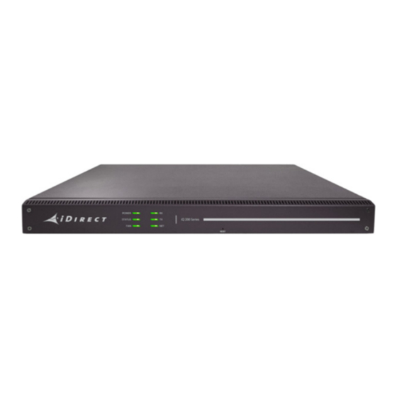
Section 1.1, Features on page 1 • Section 1.2, Power Supply Options on page 2 This manual explains how to safely install and maintain the iQ 200 Rackmount Satellite Router. The iQ 200 Rackmount Satellite Router is shown in Figure 1-1. -
Page 16: Power Supply Options
Power Supply Options Power Supply Options NOTE: The iQ 200 Rackmount can be ordered in any of the two configurations specified in Table 1-1. The Power Supply Unit (PSU) is a Field Replaceable Unit (FRU) and can be swapped in the field. -
Page 17: Specifications
Section 2.2, Power Specifications on page 4 • Section 2.3, RF Specifications on page 5 Mechanical and Environmental Specifications The installation site must be able to accommodate the iQ 200 Rackmount Satellite Router mechanical and environmental specifications. The mechanical and environmental specifications are listed in Table 2-1. -
Page 18: Power Specifications
Vibration Operational ETSI 300 019-2-6 Class 6.1, 5-200Hz Power Specifications The iQ 200 Rackmount Satellite Router power specifications are listed in Table 2-2. CAUTION: If negative voltages are used such as Telecom -48VDC, the negative most voltage is always connected to –ve terminal (in the Telecom case this would be -48V) and the positive most voltage is always connected to the +ve terminal (in the Telecom case this would be 0VR). -
Page 19: Rf Specifications
Description DC Input Connector Self-capturing terminal block, 14-18 AWG Efficiency of the Power 87% (MIN) Supply RF Specifications The iQ 200 Rackmount Satellite Router RF specifications are listed in Table 2-3. Table 2-3. RF Specifications Category Description LNB Support 22 kHz tone for High / Low Band IF Interface, Impedance Type “F”, Zo = 75 ohms... - Page 20 RF Specifications Table 2-3. RF Specifications (continued) Category Description Transmitter Muting 50 dB (min) between carrier on and off states within 0.1 us at the same attenuation state Installation, Support, and Maintenance Guide iQ 200 Rackmount Satellite Router...
-
Page 21: Interfaces
3 Interfaces This chapter describes the iQ 200 Rackmount Satellite Router physical interfaces and LEDs, and contains the following sections: • Section 3.1, iQ 200 Rackmount Satellite Router Front LEDs on page 7 • Section 3.2, iQ 200 Rackmount Front Panel LED Status Descriptions on page 8 •... -
Page 22: Iq 200 Rackmount Front Panel Led Status Descriptions
Figure 3-1 on page 7 shows the front panel and Table 3-2 describes the front panel LED color and status information: Table 3-2. iQ 200 Rackmount Satellite Router Front Panel LED Descriptions Signal Label Definition Color/Type Indicates the fan status... - Page 23 200 Rackmount Front Panel LED Status Descriptions Table 3-2. iQ 200 Rackmount Satellite Router Front Panel LED Descriptions (continued) Signal Label Definition Color/Type Solid Amber Transmitter is disabled 1 second Transmitter acquiring upstream connection flashing Amber Solid Green Transmitter upstream connection acquired...
-
Page 24: Iq 200 Rackmount Satellite Router Rear Panel Descriptions
200 Rackmount Satellite Router Rear Panel Descriptions iQ 200 Rackmount Satellite Router Rear Panel Descriptions The iQ 200 Rackmount Satellite Router rear panel is displayed in Figure 3-2 and defined in Table 3-3 on page Figure 3-2. iQ 200 Rackmount Satellite Router Rear Panel Description Table 3-3. - Page 25 200 Rackmount Satellite Router Rear Panel Descriptions Table 3-3. iQ 200 Rackmount Satellite Router Rear Panel Descriptions (continued) Callout Label Interface Definition and Connector Type 13 and 14 ETH1 and ETH2 Ethernet Communications Ports, RJ-45 10/100/1000 Ethernet ports, 802.1q VLAN NOTE: The Ethernet ports are 1G.
- Page 26 200 Rackmount Satellite Router Rear Panel Descriptions Installation, Support, and Maintenance Guide iQ 200 Rackmount Satellite Router...
-
Page 27: Installation
• Section 4.5, Mounting the iQ 200 Rackmount Satellite Router on page 16 • Section 4.6, Preparing the PC for Connection to the iQ 200 Rackmount Satellite Router on page 18 • Section 4.7, Configuring the iQ 200 Rackmount Satellite Router on page 18... -
Page 28: Installation Checklist
Do not overload wall outlets, extension cords, or integral convenience receptacles • Heat Do not place the iQ 200 Rackmount Satellite Router near heat sources, such as radiators, heat registers, stoves, or other products (including amplifiers) that produce heat •... -
Page 29: Tools And Supplies Required For Installation
10. Prepare PC for iQ 200 Rackmount Satellite Router connection as specified in Section 4.6, Preparing the PC for Connection to the iQ 200 Rackmount Satellite Router on page 11. Login PC to the user interface. 12. Install the firmware and configure the satellite router as specified in Section 4.7,... -
Page 30: Components Typically Included In An Order
Section 5.5, Repacking the iQ 200 Rackmount Satellite Router on page 22 for repacking information. Remove items from the box only as needed. Verify all of the proper iQ 200 Rackmount Satellite Router components and accessory items listed in the order have been received, including the optional equipment ordered. See Section 4.4, Components Typically Included in... -
Page 31: Installing With An Ac Power Supply (Option 1)
1. First, perform steps 1-6 of the Installation Checklist, Section 4.1, on page 2. Connect the TX and RX coax cables to the iQ 200 Rackmount Satellite Router and secure but do not over-tighten. See C.1, Coax Cable Preparation on page 29 for preparation details. -
Page 32: Preparing The Pc For Connection To The Iq 200 Rackmount Satellite Router
• Has a Web browser installed • Has an IP address that is on the same subnet of the iQ 200 Rackmount Satellite Router • Includes a Network Interface Card (NIC) connected with a CAT 5 Ethernet cable Configuring the iQ 200 Rackmount Satellite... -
Page 33: Maintenance
WARNING: Do not attempt to service the router internal assemblies, as opening and removing covers may expose personnel to dangerous voltages or other hazards. There are no user serviceable parts inside. When an iQ 200 Rackmount Satellite Router requires service, observe the safety guidelines in this section. 5.1.1 Servicing Do not attempt to service the iQ 200 Rackmount Satellite Router internal assembly. -
Page 34: Maintaining The Iq 200 Rackmount Satellite Router
(adjust only those controls that are covered by the operating instructions) • If the iQ 200 Rackmount Satellite Router has been dropped or if the chassis has been damaged • When the iQ 200 Rackmount Satellite Router exhibits a distinct change in performance... -
Page 35: Troubleshooting The Iq 200 Rackmount Router
Table 5-1 describes the most common iQ 200 Rackmount Satellite Router troubleshooting events and actions. Consult with the iDirect TAC when considering a reset. Reset functions are described in Section E, iQ 200 Rackmount Satellite Router Reset on page 41. -
Page 36: Repacking The Iq 200 Rackmount Satellite Router
Plug power cord into power supply input receptacle Repacking the iQ 200 Rackmount Satellite Router If the iQ 200 Rackmount Satellite Router system is damaged or if the chassis needs to be moved to another location, the unit needs to be repacked in the original shipping boxes. -
Page 37: Appendix A Acronyms And Abbreviations
BaseBand deciBel isotropic Below-Decks Interface Module deciBel milli-Watt BIST Built-In Self-Test deciBel Watt BITE Built-In Test Equipment Direct Current BUC Part Number Double Data Rate BPSK Binary Phase Shift Keying Installation, Support, and Maintenance Guide iQ 200 Rackmount Satellite Router... - Page 38 Loss of Signal Gain over Temperature Line-Replaceable Unit GigaHertz GPIO General-Purpose Input/Output Global Positioning System Mbps Megabits per second Mcps Megachips per second Mobile Earth Station High-Capacity Payload MF-TDMA Multi-Frequency TDMA Installation, Support, and Maintenance Guide iQ 200 Rackmount Satellite Router...
- Page 39 Preliminary Design Review TDMA Time Division Multiple Access Phased Locked Loop Terminal Functional ID Phase Shift Keying Terminal Manufacturer ID Power Supply Unit TPCFEC Turbo Product Code FEC Terminal Part Number Installation, Support, and Maintenance Guide iQ 200 Rackmount Satellite Router...
- Page 40 Terminal Serial Number Terminal Transmit Control Tx or TX Transmit Universal Data Protocol Underwriters Laboratories Volts Alternating Current Volts Direct Current VSAT Very Small Aperture Terminal Weighted Fair Queuing Wideband Global SATCOM Installation, Support, and Maintenance Guide iQ 200 Rackmount Satellite Router...
-
Page 41: Appendix B Tools Needed
Table B-1. Recommended Installation Tools and Equipment Quantity Tool Number 2 Phillips screwdriver F-type Compression Tool RG-6 Coax Stripper Coax / Wire Cutter Length as Needed RG-6 or RG-11 solid copper conductor coax outdoor rated cable Installation, Support, and Maintenance Guide iQ 200 Rackmount Satellite Router... - Page 42 Installation, Support, and Maintenance Guide iQ 200 Rackmount Satellite Router...
-
Page 43: Appendix C Cable Preparation
In general, specific and detailed instructions are for RG-6 cables and connectors, only. Use high quality coaxial outdoor cable to connect the iQ 200 Rackmount Satellite Router to the Outdoor Unit (ODU) equipment. iDirect recommends that a solid copper center conductor,... -
Page 44: Figure C-1. Coax Cable Cutting Technique
C-1. For RG-6, use a two-step Coax Stripper such as the LC-CST 1257 from Paladin Tools. Table C-1. Coax Trim Dimensions Length A Length B Length C (inch (mm)) (inch (mm)) (inch (mm)) RG-6 5/8 (15.9) 1/4 (6.4) 3/8 (9.5) Installation, Support, and Maintenance Guide iQ 200 Rackmount Satellite Router... -
Page 45: Figure C-2. Cutting Technique For Removing Foil In The Braid
Table C-1. Coax Trim Dimensions RG-11 13/32 (10.3) 3/32 (2.4) 13/32 (10.3) 3. Remove any foil in the braid as shown in Figure C-2. Figure C-2. Cutting Technique for Removing Foil in the Braid Installation, Support, and Maintenance Guide iQ 200 Rackmount Satellite Router... -
Page 46: Figure C-3. Procedure To Cut The Quad Shield Cable
NOTE: The white colored inner dielectric insulation should be flush with the inner rear surface of the connector. Refer to the picture on the right (C) in Figure C-4 for an RG-6/RG-11 termination. Installation, Support, and Maintenance Guide iQ 200 Rackmount Satellite Router... -
Page 47: Figure C-4. Attaching The Compression Fitting F-Type Connector
It must be straight and cylindrical without any burrs at the end. Failure to follow this technique could result in damage to the satellite router, BUC, LNB connector and/or possible intermittent service. Installation, Support, and Maintenance Guide iQ 200 Rackmount Satellite Router... -
Page 48: Ethernet Port Pinouts
LAN 1 port is the recommended port to connect the Ethernet cable to the Ethernet port on the PC running the user interface. Either crossover or straight through cables may be used with the iQ 200 Rackmount Router. It is not necessary for the PC to auto-sense. Details of the iQ 200 Rackmount Router LAN/Ethernet port pinouts are described in Section C.2.1... -
Page 49: Straight Through And Crossover Rj-45 Cables
(8) data bits, no (N) parity bit, and one (1) stop bit, (115200/8-N-1) The signal and pinouts for the asynchronous serial Console port (RS-232) of the iQ 200 Rackmount Router and an RJ-45 to DB-9 female DTE adapter are listed in Table C-3. -
Page 50: Figure C-8. Rj-45 To Db-9 Female Dte Adapter
Console Port RJ-45 to DB-9 Console RJ-45 Pin Color Code (DTE) Terminal Adapter Device Orange Black Green Yellow Brown Rx-RF-Power White/Grey Not Connected Figure C-8. RJ-45 to DB-9 Female DTE Adapter Installation, Support, and Maintenance Guide iQ 200 Rackmount Satellite Router... -
Page 51: Table D-1. Iq 200 Rackmount Router Dc Power Module Connector Parts
D-1. “At a Glance” instructions are in Figure D-1 on page 38 with corresponding detailed steps in Table D-2 on page Table D-1. iQ 200 Rackmount Router DC Power Module Connector Parts Name Description Diagram or Reference DC Terminal block... -
Page 52: Figure D-1. Dc-Dc Power Supply Assembly At A Glance
DC terminal block plug. Fasten the three screws securely. Do not over-tighten. Insert the cable tie through one of the holes in the right half of the strain relief clip. Installation, Support, and Maintenance Guide iQ 200 Rackmount Satellite Router... - Page 53 2. Insert the finished terminal block plug, with the cable entry housing, into the terminal block header in the power supply. Installation, Support, and Maintenance Guide iQ 200 Rackmount Satellite Router...
- Page 54 Installation, Support, and Maintenance Guide iQ 200 Rackmount Satellite Router...
- Page 55 Appendix E iQ 200 Rackmount Satellite Router Reset The iQ 200 Rackmount Satellite Router has two types of reset functions: Level 0, and Level 1. Each type has a different effect on the router. Contact the iDirect TAC center for more information.
- Page 56 Router boots with factory default image (default options file, software, and passwords), access to Terminal WUI is available at the Management port ETH 2 at 192.168.0.1 • Recovery: none - reload software, options file, configuration Installation, Support, and Maintenance Guide iQ 200 Rackmount Satellite Router...
- Page 58 13861 Sunrise Valley Drive, Suite 300 Herndon, VA 20171-6126 +1 703.648.8000 +1 866.345.0983 www.idirect.net Advancing a Connected World...
Need help?
Do you have a question about the iQ 200 and is the answer not in the manual?
Questions and answers