iDirect X1 Installation, Support, And Maintenance Manual
Evolution satellite router
Hide thumbs
Also See for X1:
- Installation and safety manual (60 pages) ,
- Installation manual (130 pages) ,
- Installation and safety manual (80 pages)

Related Manuals for iDirect X1


Summary of Contents for iDirect X1
-
Page 1: Maintenance Guide
Evolution X1 Satellite Router Installation, Support, and Maintenance Guide Installation, Support, and Maintenance Guide Evolution X1 Satellite Router Router Products June 28, 2013... - Page 2 Copyright © 2013 VT iDirect, Inc. All rights reserved. Reproduction in whole or in part without permission is prohibited. Information contained herein is subject to change without notice. The specifications and information regarding the products in this document are subject to change without notice. All statements, information, and recommendations in this document are believed to be accurate, but are presented without warranty of any kind, express, or implied.
-
Page 3: Revision History
To verify the latest version, access the TAC Web site at http://tac.idirect.net. Updated by Revision Date Released Reason for Change(s) June 30, 2013 Initial release. JScott Installation, Support, and Maintenance Guide Evolution X1 Satellite Router... - Page 4 Revision History Installation, Support, and Maintenance Guide Evolution X1 Satellite Router...
-
Page 5: Table Of Contents
..........9 3.1 X1 Router (Indoor) Specifications ....... . 10 . - Page 6 4.1 X1 Router (Indoor) Interfaces ........
- Page 7 7.1.2 Conditions Requiring Service 7.2 Maintaining the X1 Router (Indoor) ....... 53 .
- Page 8 ......69 Appendix E X1 Reset ......... . 73 E.1 Level 0 Reset .
- Page 9 Figure 6-4. X1 Outdoor Router Wall Mount ........
- Page 10 Table 6-1. RJ 45 LAN Ethernet Cable Installation Steps..........43 Table 6-2. Coax RX and TX Cable Installation ............44 Table 6-3. X1 Outdoor Router Power Module DC to DC Installation Instructions ....45 Table 6-4. Power Module Power Cable Installation Instructions ........47 Table 6-5.
-
Page 11: About
This manual is intended for use by the VSAT (Very Small Aperture Terminal) equipment installer, System Engineer, and Network Operator responsible for maintaining the iDirect Network. Only qualified service personnel should install and operate the X1 Router solutions. Familiarity with cabling and wiring practices is beneficial. -
Page 12: Document Conventions
• Appendix D, DC Power Supply Installation on page 69 provides instructions for assembly of the X1 Indoor router’s DC power module strain relief and terminal block plugs • Appendix C, Ethernet and Console RJ45 Pinouts on page 65 describes the pinouts for the NET connection •... -
Page 13: Safety Definitions
(800) 648-8240 for class registration and information. Getting Help iDX Software user’s guides, installation procedures and guides, an FAQ page, and other documentation that supports iDirect products, are available on the TAC Web site located at: http://tac.idirect.net. Installation, Support, and Maintenance Guide... - Page 14 To find answers to questions or information, contact the iDirect Technical Assistance Center (TAC) at (703) 648-8151. iDirect makes every effor to produce documentation that is technically accurate, easy to use, and helpful to our customers. Feedback is welcomed! Send comments to techpubs@idirect.net.
-
Page 15: Introduction
1 Introduction The Evolution X1 Satellite Router is optimized for use in large networks with small inbound channels such as SCADA, point-of-sale and ATM. The X1 features DVB-S2/ACM, TDMA, basic routing and VLAN functionality at a cost-effective price point. This chapter contains the following sections: •... -
Page 16: X1 Outdoor Router
X1 Outdoor Router X1 Outdoor Router The iDirect Evolution X1 Outdoor Satellite Router is a cost-effective remote bundle ideal for large, narrowband networks for SCADA, femtocells or pipeline monitoring. The X1 Outdoor Router features DVB-S2/ACM and TDMA, basic routing, VLAN functionality and Quality of Service (QoS), and is embedded in a IP67 weatherproof enclosure enabling an extended temperature range, and passive cooling. -
Page 17: Safety
Keep this safety information handy to where it is easily referred. Read this entire chapter before attempting to install or use the X1 Router. Adhere to all warnings listed on the product’s warning labels and in the operating instructions. Follow all operating and usage instructions carefully. -
Page 18: Installation Safety Guidelines
These guidelines may not cover all of the potentially hazardous situations that may be encountered during installation. The installation of the X1 Router must comply with the national and local electrical codes, as follows: •... -
Page 19: Electrical Safety
Do not perform any action that creates a potential hazard to people or makes the equipment unsafe. Never install equipment that appears damaged • Carefully examine the work area for possible hazards, such as wet floor, ungrounded power extension cables, and missing safety grounds Installation, Support, and Maintenance Guide Evolution X1 Satellite Router... -
Page 20: Physical And Environmental Considerations
(including amplifiers) that produce heat. • Accessories To avoid personal injury or damage to the X1 Router, do not place the chassis on any unstable rack, cart, stand, table, or bracket. Any mounting of the product should follow the manufacturer’s instructions. - Page 21 • Operational and Maintenance Safety As the X1 Router is used, the following safety guidelines must be observed: • Cables — Never use any other RF cable than what is supplied or recommended by iDirect •...
- Page 22 Physical and Environmental Considerations Installation, Support, and Maintenance Guide Evolution X1 Satellite Router...
-
Page 23: Specifications
3 Specifications The specifications in this chapter describe the mechanical, environmental and RF specifications for the Evolution X1 Satellite Router. The installation site must accommodate the mechanical and environmental specifications of the X1 Router. This chapter contains the following sections: •... -
Page 24: X1 Router (Indoor) Specifications
Storage 3.1.2 Power Specifications Table 3-2 provides the power specifications for the router and the typical BUC/LNB for the X1 Router (Indoor). NOTE: Only use the iDirect approved and provided power supply. Table 3-2. X1 Router (Indoor) Power Specifications Category... -
Page 25: Rf Specifications
X1 Router (Indoor) Specifications Table 3-2. X1 Router (Indoor) Power Specifications (continued) Category Description Protection Internal, primary current fuse, inside power supply Over current protection Short circuit protection Power Factor Correction Option 1 (only): Complies with EN61000-3-2 and EN61000-3-3 Input Transient Response 0.5 ms for 50% Load Change (TYP) - Page 26 X1 Router (Indoor) Specifications Table 3-3. X1 Router (Indoor) RF Specifications (continued) Category Description Typical Transmit and Receive Phase Noise (dBc/Hz) at: Frequency Phase Noise 1 KHz 10 KHz 100 KHz Typical Phase Jitter at 1.8 rms 14 KHz to 1 MHz ...
-
Page 27: X1 Outdoor Router Specifications
Description Dimensions X1 Router: W 10.25 in (26.04 cm) x H 10 in (25.4 cm) x D 3 in (7.62 cm) Power Module: W 5 in (12.7cm) x H 8.75 in (22 cm) x D 2.25 in (5.7 cm) Weight X1 Router: 5 lbs (2.27 kg) -
Page 28: Power Specifications
NOTE: Only use the iDirect approved and provided power supply. NOTE: The power supply provides power to the external Power Module. The Power Module supplies DC power only to the X1 Outdoor Router. Table 3-5. X1 Outdoor Router Power Specifications... -
Page 29: Rf Specifications
X1 Outdoor Router Specifications 3.2.3 RF Specifications The X1 Outdoor Router RF specifications are defined in Table 3-3. Table 3-6. X1 Outdoor Router RF Specifications Category Description Frequency Range Transmit 950-1700 MHz, Composite Power 0 dBm/-30 dBm Receive 950-2150 MHz, Composite Power -5 dBm/-65dBm... - Page 30 X1 Outdoor Router Specifications Installation, Support, and Maintenance Guide Evolution X1 Satellite Router...
-
Page 31: Physical Interfaces
4 Physical Interfaces This chapter describes physical interfaces and LEDs on the X1 Router (Indoor) and the physical interfaces and LED on the X1 Outdoor Router. This chapter contains the following sections: • Section 4.1, X1 Router (Indoor) Interfaces on page 18 •... -
Page 32: X1 Router (Indoor) Interfaces
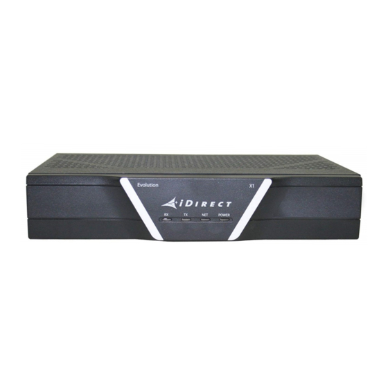
X1 Router (Indoor) Front Panel Power and Network LED Status Indicators Once the X1 Router (Indoor) is powered up with the appropriate Options file, check the LEDs to confirm the router is functioning properly. The front panel indicators are shown in... -
Page 33: X1 Router (Indoor) Rear Panel
X1 Router (Indoor) Interfaces Table 4-1. X1 Router (Indoor) Panel LED Indicators (continued) LED Label LED Color Indicated X1 Status Flashing Yellow Demodulator is not locked on the Downstream carrier. Solid Yellow Demodulator is locked on the Downstream carrier. 2 Second Flashing Green Demodulator is locked on the Downstream carrier. -
Page 34: X1 Outdoor Router Interfaces
Interface (Web iSite) provides four simulated LEDs, reflecting the LEDs, similar to the X1 Router (Indoor). The simulated LED displayed colors (red, yellow, green) indicate the state of the X1 Outdoor Router and are documented in the iDX Web iSite User Guide, iDX Satellite Router Installation and Commissioning Guide, and iDX Release Notes. -
Page 35: Figure 4-3. X1 Outdoor Router Panel
LAN Hub switch; See Appendix C, Ethernet and Console RJ45 Pinouts on page 65 Power LED POWER No or low DC power input to the X1 Outdoor Router. Solid Red Acceptable DC power level to the X1 Outdoor Router is detected. -
Page 36: X1 Outdoor Router Power Module Unit Connectors
Cat 5 - Cat 7 Gland (gland supplied with order) 4.2.2 X1 Outdoor Router Power Module Unit Connectors The Power Module interface connectors for the X1 Outdoor Router are shown in Figure 4-4 described in Table 4-5. The pin assignments for the AC power connector are defined in... -
Page 37: Table 4-6. Pin Assignments For Ac Power Module Gland (4 Pin)
X1 Outdoor Router Interfaces Table 4-5. X1 Outdoor Router Power Module Connector Descriptions Callout Label Description DC (24VDC 2.7A) Option 1: 24 VDC 2.7 A DC power connector to Router Power Connector to Options 2 & 3: 24 V 2.7 A Router Table 4-6. - Page 38 X1 Outdoor Router Interfaces Installation, Support, and Maintenance Guide Evolution X1 Satellite Router...
-
Page 39: X1 Router (Indoor) Installation
5 X1 Router (Indoor) Installation This chapter describes the guidelines and procedures for installing the iDirect Evolution X1 Satellite Router (Indoor) at the VSAT location. This chapter contains the following sections: • Section 5.1, X1 Router (Indoor) Installation at a Glance on page 26 •... -
Page 40: X1 Router (Indoor) Installation At A Glance
When selecting the site, consider accessibility, availability of power, signal and network connections, and the possibility of future expansion • Install the X1 Router (Indoor) in a location where access is unobstructed. Plan for access to both the front and rear panels •... -
Page 41: Unpacking X1 Router (Indoor) Equipment
Chapter 7, Maintenance on page Unpacking X1 Router (Indoor) Equipment The X1 Router (Indoor) and related equipment, may be shipped in one or more containers, depending on the type of bundle purchased. Once all of the boxes have been received, perform the following tasks: •... -
Page 42: X1 Router (Indoor) Mounting
NOTE: The X1 Router (Indoor) is designed for indoor use only. 5.4.1 Guidelines for Desktop or Shelf Mounting If the X1 Router (Indoor) is mounted in an enclosed shelf, the shelf must have adequate ventilation. An enclosed shelf should have openings on the sides and top to provide air circulation. -
Page 43: Powering On The X1 Router (Indoor)
X1 Router (Indoor). CAUTION: Do not connect or disconnect the Tx or Rx IFL cable during the time the X1 Router (Indoor) is being powered on; this action may result in damage to the BUC, LNB, and/or X1 Router (Indoor). -
Page 44: Powering Up The System
The LAN port is normally assigned to the WAN (towards the VPN). Its IP address is the next hop for the VPN. The IP address of the X1 Router, 192.168.0.1, is important to have to be able to use the Web Interface program (Web iSite). -
Page 45: Monitoring The Leds
Table 4-1 on page 18 for a detailed description of the states of the LEDs. For diagnostic purposes, the X1 Router (Indoor) displays four LEDs in the Web Interface software (see, iDX Web iSite User Guide): NOTE: The LED displayed colors (red, yellow, green) indicate the state of the X1 Router and are documented in the iDX Web iSite User Guide, iDX Satellite Router Installation and Commissioning Guide, and iDX Release Notes. -
Page 46: Configuring The X1 Router (Indoor)
Configuring the X1 Router (Indoor) Configuring the X1 Router (Indoor) When the X1 Router (Indoor) has been installed, next step is installing the firmware and configuring the satellite router. For instructions on how to do this, refer to the iDX Satellite Router Installation and Commissioning Guide. -
Page 47: X1 Outdoor Router Installation
6 X1 Outdoor Router Installation This chapter describes the guidelines and procedures for installing the X1 Outdoor Router. This chapter contains the following sections: • Section 6.1, X1 Outdoor Router Installation at a Glance on page 34 • Section 6.2, Unpacking X1 Outdoor Router Equipment on page 35 •... -
Page 48: X1 Outdoor Router Installation At A Glance
• Install the X1 Outdoor Router in a location where access is unobstructed • Do not install the X1 Outdoor Router on the floor. Install only on a wall or pole. • Use only the iDirect approved Power Module •... -
Page 49: Unpacking X1 Outdoor Router Equipment
One Power Module, either Option 1, 2, or 3, with connectors, see Section 6.4, on page 36 • Two (2) hardware mounting kits (one for the X1 Outdoor Router and one for the power module for wall or pole mounting, see Figure 6-1 on page 36, items labeled A and E: •... -
Page 50: Installation With Ac (Option 1) Or Dc (Options 2 And 3) Power Supplies
6.4.1 Installation with AC Power Supply to the Power Module - Option 1 (AC) For an X1 Outdoor Router with an AC power supply: 1. Assemble the AC power gland, as described in Section 6.9.2, Connecting Power Supply to The Power Module on page... -
Page 51: Installation With Dc Power Supply To The Power Module - Option 2 And Option 3 (Dc)
Figure 4-4 on page 22 for Power Module connector descriptions. X1 Outdoor Router Mounting The X1 Outdoor Router must be mounted to a wall or to a pole. This section provides details for an outdoor installation. 6.5.1 Pre-Installation Guidelines for Mounting Configurations When installing the X1 Outdoor Router, follow these guidelines: •... -
Page 52: Figure 6-2. Router Mounting Kit Parts
X1 Outdoor Router Mounting • 1 mounting plate • 2 stainless steel tie back straps • 4 wood screws • 4 wood/gyprock plugs (anchors) • 4 M6x20 screws • 4 flat washers for M6 screws • 4 spring (lock) washers for the M6 screws •... -
Page 53: Attaching The Mounting Plate To The Router
Figure 6-3. Attaching the Mounting Plate 6.5.3.1 Router Wall Mount After attaching the mounting plate to the router, mount the X1 Outdoor Router to a wall, mount the assembly to the wall using the four wood screws and wood/gyprock plugs as shown Figure 6-4. -
Page 54: External Power Module Mounting Instructions
External Power Module Mounting Instructions 6.5.3.2 Router Pole Mount After attaching the mounting plate to the router, mount the X1 Outdoor Router to a pole, mount the assembly to the pole using the two stainless steel tie back straps as shown in Figure 6-5 (various mounting options are shown). -
Page 55: Attaching The Mounting Plate To The Power Module
6.6.1.1 Wall Mount After attaching the mounting plate to the Power Module, mount the Power Module assembly to the wall as shown in Figure 6-7. Figure 6-7. Power Module Wall Mount Installation, Support, and Maintenance Guide Evolution X1 Satellite Router... -
Page 56: Connecting The Ethernet Lan Cable
CAUTION: All cables should be installed with a drip loop or service loop. NOTE: The X1 Outdoor Router connectors and cable for Ethernet may be attached before or after mounting on a wall or pole. -
Page 57: Table 6-1. Rj 45 Lan Ethernet Cable Installation Steps
1. Clip the RJ45 connector and cable into the RJ45 receptacle. 2. Screw the sealing nut (A) into the X1 Outdoor Unit. 3. Push the compression ring (B) into the sealing nut (A). 4. Pass the lock nut body (C) over the compression ring (B). -
Page 58: Preparing And Connecting The Coax Rx And Tx Cables
(self-amalgamate) tape, if necessary, following manufacturer’s guidelines. CAUTION: All cables should be installed with a drip loop or service loop. NOTE: The X1 Outdoor Router connectors and cables for power, TX, RX, and Ethernet may be attached before or after mounting on a wall or pole. -
Page 59: Connecting The Dc Power Module
Repeat step 1 and step 2 for TX-out interface. Connecting the DC Power Module This section details connecting the DC to DC power from the Power Module to the X1 Outdoor Router and connecting the AC power to the Power Module. 6.9.1... -
Page 60: Connecting Power Supply To The Power Module
Connecting the DC Power Module Table 6-3. X1 Outdoor Router Power Module DC to DC Installation Instructions Step Instructions Diagram Final X1 Outdoor Router DC power connection completed; proceed to step 3. Lock the opposite end of the DC power cord into the Power Module. -
Page 61: Table 6-4. Power Module Power Cable Installation Instructions
AC power) or Table 4-7 on page 23 (for DC power). 2. Using the Allen Wrench (provided), tighten the pin screws for each of the power wires in the Female Housing Assembly. Installation, Support, and Maintenance Guide Evolution X1 Satellite Router... -
Page 62: Powering Up The System
6.10 Powering Up the System The X1 Outdoor Router can only be powered directly from the Power Module’s DC power output connector. iDirect recommends that the chassis of the Power Module be powered from a low noise, low transient power source. -
Page 63: Powering Up The System
There is a weather sealed power LED indicator on the right side of the Ethernet connector. When power is detected and the X1 Outdoor Router is powered up, the LED light is solid red. If no power is detected, the LED is off. -
Page 64: Preparing The Pc/Laptop For Connection To The X1 Outdoor Router
6.12 Front Panel Power Indicator and Web Interface LED Status Indicators The X1 Outdoor Router has a single LED light on the front panel signifying that the power is either on or off, with a solid red LED meaning . However, the Web Interface software (Web iSite) displays a detailed status interpretation with a virtual panel of four LED status indicators. -
Page 65: Configuring The X1 Outdoor Router
Configuring the X1 Outdoor Router 6.13 Configuring the X1 Outdoor Router When the X1 Outdoor Router is physically installed, the firmware and configuration of the satellite router need to be completed. For instructions on how to do this, refer to the iDX Satellite Router Installation and Commissioning Guide. - Page 66 Configuring the X1 Outdoor Router Installation, Support, and Maintenance Guide Evolution X1 Satellite Router...
-
Page 67: Maintenance
Do not attempt to service the X1 Router internal assemblies, as opening and removing covers may expose personnel to dangerous voltages or other hazards. There are no user serviceable parts inside. Opening the X1 Router or Power Module will void the warranty. Refer all servicing to qualified service personnel. -
Page 68: Temperature Control
Maintaining the X1 Outdoor Router Typically, the only maintenance needed to be performed on the unit, without explicit directions from iDirect, is to maintain the temperature of the X1 Router (Indoor) and keep its external areas free from dust or dirt. -
Page 69: Temperature Control
Make sure that the ambient temperature remains within the specified limits Repacking the X1 Router If the X1 Router system is damaged, or if the chassis needs to be moved to another location, the unit needs to be repacked in the original shipping boxes. - Page 70 Repacking the X1 Router Installation, Support, and Maintenance Guide Evolution X1 Satellite Router...
-
Page 71: Appendix A Tools Needed
NOTE: The tools intended for use in this section are intended to be generic. Equipment should be installed per manufacturer’s requirements specific to the brands preferred. This section describes tools needed for X1 Router installation. A.1 Indoor Coax Installation Tools Needed Table A-1... -
Page 72: Outdoor (Odu) Coax Installation Tools Needed
Figure A-1 Table A-3 specify recommended tools and supplies for a typical installation. Table A-2. Tools Included in the order Quantity Tool 1.5 mm Allen wrench Installation, Support, and Maintenance Guide Evolution X1 Satellite Router... -
Page 73: Table A-3. Recommended Installation Tools And Equipment For Outdoor Coax
Length of outdoor rated Ethernet LAN cable (Optional) Wrench for securing/un-securing the plastic sealing nut designated as part A in Table 6-1, RJ 45 LAN Ethernet Cable Installation Steps on page Installation, Support, and Maintenance Guide Evolution X1 Satellite Router... - Page 74 Outdoor (ODU) Coax Installation Tools Needed Installation, Support, and Maintenance Guide Evolution X1 Satellite Router...
-
Page 75: Appendix B Preparing The Coax Cable
In general, specific and detailed instructions are for RG-6 cables and connectors, only. Use high quality coaxial outdoor cable to connect the Evolution X1 Satellite Router to the Outdoor Unit (ODU) equipment. iDirect recommends that a solid copper center conductor,... -
Page 76: Figure B-1. Coax Cable Cutting Technique
(inch (mm)) (inch (mm)) (inch (mm)) RG-6 5/8 (15.9) 1/4 (6.4) 3/8 (9.5) RG-11 13/32 (10.3) 3/32 (2.4) 13/32 (10.3) 3. Remove any foil in the braid as shown in Figure B-2. Installation, Support, and Maintenance Guide Evolution X1 Satellite Router... -
Page 77: Figure B-2. Cutting Technique For Removing Foil In The Braid
RG-6/RG-11 termination. 9. Since the RG-11 connector has a built-in center pin, ensure that the coax center pin makes contact to the internal seizing pin of the connector. Refer to Figure C-3. Installation, Support, and Maintenance Guide Evolution X1 Satellite Router... -
Page 78: Figure B-4. Attaching The Compression Fitting F-Type Connector
It must be straight and cylindrical without any burrs at the end. Failure to follow this technique could result in damage to the satellite router, BUC, LNB connector and/or possible intermittent service. Installation, Support, and Maintenance Guide Evolution X1 Satellite Router... -
Page 79: Appendix C Ethernet And Console Rj45 Pinouts
10-Mbps and 100-Mbps transmission over Unshielded Twisted-Pair (UTP) cables. Use Category-3 or Category-5 UTP cable with RJ-45 connectors to attach the 10/100 Base-T Ethernet LAN A port on the Evolution X1 Satellite Router chassis to the customer provided LAN Hub or switch. -
Page 80: Console Port Pinouts And Rj-45-Db9 Female Dte Adapter Pinouts
DB-9 female DTE adapter may be used to connect the console port to the PC running terminal emulation software. The signal and pinouts for the asynchronous serial console port of the X1 Router and the RJ-45 to DB-9 female DTE adapter are listed in Table C-2. -
Page 81: Figure C-3. Rj-45 To Db-9 Female Dte Adapter
Terminal Adapter Device Yellow Brown Rx-RF-Power White/Grey Not Connected A picture of the RJ-45 to DB-9 Female DTE adapter is shown in Figure C-3. Figure C-3. RJ-45 to DB-9 Female DTE Adapter Installation, Support, and Maintenance Guide Evolution X1 Satellite Router... - Page 82 Console Port Pinouts and RJ-45-DB9 Female DTE Adapter Pinouts Installation, Support, and Maintenance Guide Evolution X1 Satellite Router...
-
Page 83: Appendix D Dc Power Supply Installation
Appendix D DC Power Supply Installation This appendix describes the installation of the DC power supply wiring for the X1 Router (Indoor), Option 2. A summary of the parts are listed in Table D-1. Follow the at a glance instructions in... -
Page 84: Figure D-1. Dc-Dc Power Supply Assembly At A Glance
Table D-1. X1 Router (Indoor) DC Power Module Connector Parts Name Description Diagram or Reference Included in kit, P/N Phoenix Terminal block plug 1754465 Cable Entry Housing Cable Entry Housing Strain Strain Relief and Relief and Cable Tie, included Cable Tie in kit, P/N 1803947, and cable Figure D-1. - Page 85 Be sure the two end screw holes fit securely into the two small protruding screw holders. Clip the other half of the strain relief clip around the cable entry housing and tighten the cable tie. Installation, Support, and Maintenance Guide Evolution X1 Satellite Router...
- Page 86 Table D-2. Power Module Power Cable Installation Instructions Detail Step Instructions Diagram Insert the finished terminal block plug, with the cable entry housing, into the terminal block header in the power supply. Installation, Support, and Maintenance Guide Evolution X1 Satellite Router...
-
Page 87: Appendix E X1 Reset
Appendix E X1 Reset The X1 Router has two types of reset functions: Level 0 and Level 1. Each type has a different effect on the router. Contact the iDirect TAC center for more information. Level 0 Reset Level 0 reset provides a basic reset function. - Page 88 Router boots with factory default image (default options file, software, and passwords), access to Web iSite is available at 192.168.0.1 • Recovery: none - software, options file, configuration must be reloaded Installation, Support, and Maintenance Guide Evolution X1 Satellite Router...
Need help?
Do you have a question about the X1 and is the answer not in the manual?
Questions and answers