Table of Contents
Advertisement
Quick Links
Advertisement
Table of Contents

Related Manuals for Omega FUZZY LOGIC CN4800


Summary of Contents for Omega FUZZY LOGIC CN4800
- Page 1 Artisan Technology Group is your source for quality new and certified-used/pre-owned equipment SERVICE CENTER REPAIRS WE BUY USED EQUIPMENT • FAST SHIPPING AND DELIVERY Experienced engineers and technicians on staff Sell your excess, underutilized, and idle used equipment at our full-service, in-house repair center We also offer credit for buy-backs and trade-ins •...
- Page 2 M1791 Artisan Technology Group - Quality Instrumentation ... Guaranteed | (888) 88-SOUR...
-
Page 3: Table Of Contents
Contents I. PREPARING THE OPERATION ....... 4 1. THE BASIC INSTALLATION PROCEDURE ....2. CHECK OF SPECIFICATIONS ........2.1 CN4800 MODEL CONFIGURATION ....... 3. ACCESSORIES ..............4. INSTALLATION ..............4.1 INSTALLATION PLACE ........... 4.2 INSTALLATION PROCEDURE ........ 4.3 CAUTION ON SAFETY ..........10 4.4 PANEL CUT DIMENSIONS ........ - Page 4 III. OPERATION PROCEDURE ........33 1. OPERATION MODE/PARAMETER SETTING MODE ..33 2. VIEWING PARAMETERS ..........33 3. CHANGING PARAMETERS ..........35 IV. SETTING INPUT AND OUTPUT TYPES ....37 Changing input ................37 Changing scale (voltage/current input) ......... 41 Changing output (universal output) ..........
- Page 5 Control processing cycle time ............82 APPENDIX ..............83 1. ERROR MESSAGES ............83 2. POWER FAILURE ............83 3. SPECIFICATIONS ............84 4. TROUBLESHOOTING ............89 5. PARAMETER LIST ............91 ogy Group - Quality Instrumentation ... Guaranteed | (888) 88-SOURCE |...
-
Page 6: Preparing The Operation
I. PREPARING THE OPERATION We thank you for the purchase of this CN4800 (Fuzzy Temperature Controller). Employing FUZZY LOGIC the CN4800 virtually eliminates system overshoot and effectively suppresses fluctuation of the process variable due to external disturbances. Please read this manual, when programed and operated within the guidelines setforth in this manual, your CN4800 controller will give you years of precise, reliable control. -
Page 7: The Basic Installation Procedure
1. THE BASIC INSTALLATION PROCEDURE Is given here as to the basic flow from the installation to operate the CN4800. For detailed description of each step, see the pages correspondent. See the section “Operation Procedure” on the pages 33 to 36 for calls and changes the specific parameter. -
Page 8: Check Of Specifications
2. CHECK OF SPECIFICATIONS Please make sure that specifications of this product is according with your request. The product specifications are provided on the main unit as model configuration following. 2.1 CN4800 MODEL CONFIGURATION Contents Number of Outputs CN4801 - single output CN4802 - Dual output Output #1 Relay... - Page 9 2.2 CN4810/20 MODEL CONFIGURATION Contents Front panel dimensions: 48×96 mm for CN4810 96×96 mm for CN4820 Number of Outputs CN48X1 - Single Output CN48X2 - Dual Output Control output 1 Relay dc pulse Current (DC 4~20mA) Control output 2 Relay dc pulse Current (DC 4~20mA) Alarm function...
-
Page 10: Accessories
3. ACCESSORIES In addition to the main unit, the following accessories are shipping in the same package. Accessories Quat. Instruction manual (this manual) Panel mounting bracket set Current input resistance (250Ω) * Not delivered for TC/PT input type * Suffix means revision control 4. -
Page 11: Installation Procedure
4.2 INSTALLATION PROCEDURE Panel mounting bracket (accessorie) Panel Clamping screw Panel Clamping screw Main unit Panel mounting bracket (accessorie) For CN4800 For CN4810/20 • For CN4800 Slide the enclosed plastic panel mounting bracket (shipped with the CN4800) up the back of the controller until it makes contact with the back of the panel. -
Page 12: Caution On Safety
4.3 CAUTION ON SAFETY First of all, read this "Caution on Safety" carefully, and then use the instrument in the correct way. The cautionary descriptions listed here contain important information about safety, so they should always be observed. Those safety precautions are classified in 2 ranks, WARNING and CAUTION. - Page 13 Prior to operation of the installed system the wiring should be checked to ensure that the required levels of insulation have been provided. 2) When a fault in the instrument is likely to lead to a serious trouble, use a suitable protective circuit on the outside for protection against trouble.
- Page 14 1.4 Prohibition of use in gas The instrument is not an intrinsic safety explosion - proof type. Do not use it in a place exposed to combustible or explosive gas. 1.5 Contact to unit 1) This unit must not be disassembled, modified or repaired to prevent mal- function, shock hazard or fire accident.
- Page 15 table below. Failure to maintain these minimum distances would invalidate the EN61010 safety approval. Clearance (mm) Creepage (mm) Voltage used or generated by the other assemblies Up to 50V or V DC Up to 100V or V DC Up to 150V or V DC Up to 300V or V DC...
- Page 16 EXAMPLE INSTALLATION DIAGRAM TO MAINTAIN SAFETY OF CONTROLLER Example of how to install Controller into an environment where hazardous voltages may exist is shown below. Make sure installed system has basic insulation around this connection Thermocouple, RTD, Voltage or Current Make sure installed system has...
- Page 17 CAUTION 2.1 Caution on handling 1) Do not install the unit in any of the following places. • A place where the ambient temperature exceeds the range of -10 to 50°C • A place where the ambient humidity exceeds 90%RH •...
- Page 18 • CN4800 Insert the supplied mounting frame from the rear side and push it in until the main unit is secured firmly to the panel. If it has a slight play, tighten the 2 screws until the play is eliminated. (If the screws are tight- ened forcedly, the mounting frame may be slipped off the stopper) 3) When the unit is exposed to water, it may lead to a short-circuit or fire hazard.
- Page 19 2.3 Other When cleaning the instrument, do not use organic solvents such as alcohol, benzine, etc. Use neutral detergent. 3. Caution on key operation / trouble Alarm function should be set correctly. Otherwise, alarm output cannot be obtained at the time of occurrence of trouble. Be sure to check the function prior to operation.
-
Page 20: Panel Cut Dimensions
4.4 PANEL CUT DIMENSIONS 65 or more 100 or more or more or more +0.8 +0.5 +0.8 +0.5 For CN4800 For CN4820 When mounting multiple n units (2 ≤ n ≤ 6) When mounting one unit +0.8 +0.8 +0.8 +0.8 Units Units (mm) For CN4810... -
Page 21: Wiring
5. WIRING 5.1 CN4800 WIRING DIAGRAM [When the output 1 is relay (SPST) output, SSR drive output or current output] Option 11 12 Control output 1 Alarm Input AC100-240V — 50/60H Input TC input Pt input Voltage input Current input N.C. - Page 22 Control output 1 For relay output For SSR drive output For current output DC-V DC 4-20mA Alarm ALM2 ALM1 NOTE: Only ALM 1 is available in the case of ALM-COM the digital output type. Option For digital input For control output 2 For control output 2 For AO output (relay output)
-
Page 23: Cn4800 Wiring Diagram [When The Output 1 Is Relay (Spdt) Output]
5.2 CN4800 WIRING DIAGRAM [When the output 1 is relay (SPDT) output] Option 11 12 Control output 1 Control output 1 Alarm Input AC100-240V — — 50/60H Input TC input Pt input Voltage input Current input N.C. N.C. N.C. 250Ω —... - Page 24 Control output 1 Alarm N.C. N.O. ALM-COM Option For control output 2 For control output 2 (relay output) (SSR drive output) For digital input For AO output For current transformer input For RS485 transmission For remote SV input TRX— TRX+ ogy Group - Quality Instrumentation ...
-
Page 25: Cn4800 Wiring Diagram
5.3 CN4810/20 WIRING DIAGRAM (Not universal output) Option Control output 1 Control output 2 Alarm Input AC100~240V — 50/60H Output For TC input For Pt input For voltage input For current input N.C. N.C. N.C. 250Ω — NOTE: • For current input (4-20mA), use the accessorie resistance (250 Ω... - Page 26 Control output 1 For relay output For SSR drive output For current output N.O. N.C. DC-V DC 4-20mA Control output 2 For relay output For SSR drive output For current output N.O. N.C. DC-V DC 4-20mA Alarm ALM1 ALM2 ALM-COM ogy Group - Quality Instrumentation ...
- Page 27 Option For digital input For AO output For current transformer input For RS485 transmission For remote SV input TRX+ TRX— ogy Group - Quality Instrumentation ... Guaranteed | (888) 88-SOURCE |...
-
Page 28: (Universal Output)
5.4 CN4810/20 WIRING DIAGRAM (universal output) Option Control output 1 Control output 1 Alarm Input AC100~240V — 50/60H Input For TC input For Pt input For voltage input For current input N.C. N.C. N.C. 250Ω — NOTE: • For current input (4-20mA), use the accessorie resistance (250 Ω... - Page 29 Control output 1 For relay output For SSR drive output For current output N.O. N.C. DC-V DC 4-20mA Alarm ALM1 ALM2 ALM-COM Option For digital input For AO output For current transformer input For RS485 transmission For remote SV input TRX+ TRX—...
-
Page 30: Notes
5.5 NOTES Connection: • No power switch and fuse are provided on this product. Install them separately if necessary. • Use designated compensating wire in the case of thermo- couple input. • Use wire with line resistance lower that 10 Ω for thermoresistance input. - Page 31 Connection of Load Circuit: • When the frequency of operation is rather high, in the case of proportional operation for instance, maximum load with respect to the capacity of the output relay will result in shorter life. Use an auxiliary relay in such a case. Type SSR is recommended.
-
Page 32: Front Panel Layout
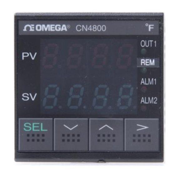
II. FRONT PANEL LAYOUT PV value display Set point value display OUT1 Control output 1 monitor lamp OUT2 Control output 2 or remote operation monitor lamp Alarm 1 lamp ALM 1 Alarm 2 lamp ALM 2 SELECT/Registration DOWN key UP key CARRIAGE/Registration CN4801 OUT1... - Page 33 PV value display Displays the measured value, as well as the failure information. When more than one failure occurs simultaneously, the failure information of the highest priority alone will be displayed. Display Meaning Priority Main unit failure High Heater disconnected Control loop failure Set point value display Displays the set point value.
- Page 34 Alarm-1 monitor lamp ALM 1 Lights when the alarm-1 relay operates Alarm 2 monitor lamp ALM 2 Lights when the alarm-2 relay operates SELECT/Registration Used to switch from the operation mode to parameter setting mode, to select parameters, and to Registration set values.
-
Page 35: Operation Procedure
III. OPERATION PROCEDURE 1. OPERATION MODE/PARAMETER SETTING MODE The operation of this device includes the Operation Mode where measured and set values are displayed and the Parameter Setting Mode where various parameters are set. To switch between the operation and parameter setting modes, continue to press the key for about 3 sec. - Page 36 * The numeric value shown in the left-hand figure is only an example. Operation Mode Continue to press key for about 3 sec parameter Parameter Setting Mode parameter • • • • parameter *Not displayed unless the transmission option is provided. ogy Group - Quality Instrumentation ...
-
Page 37: Changing Parameters
3. CHANGING PARAMETERS 1. Display the parameter to be set (to be changed) on the screen, as described in the Section 2. “Viewing Parameter” (page 33). 2. Select the digit to be set (to be changed ), with the key (the selected digit flickers). - Page 38 Example <<Changing “Lock” from 1 to 2>> Press Display the target The leftmost digit The center left digit parameter. flickers, and data of that flickers, and data of that digit is changeable. digit is changeable. The center right digit The rightmost digit flickers, and data of that flickers, and data of that digit is changeable.
-
Page 39: Setting Input And Output Types
IV. SETTING INPUT AND OUTPUT TYPES After completing wiring, make sure that the measured value is of the right type before operating the device. Parameter to be used Changing input Setting the Input type ( It refers to setting the input type (range), presence or absence of decimal- point, and units of display (°C/°F). - Page 40 4. Change the lower display to with the keys, and stop flickering and register the value with the keys. 5. Repeat pressing the key until parameter is displayed. 6. Set parameter to the desired specifications following. Example: Setting of K thermocouple for 0.0-400.0 ° C range Display unit °...
- Page 41 Input signal and measurement range Input type Measurement Measurement 0.1 C 0.1 F Input signal code range (C) range (F) display display Ο Ο Thermo- Pt100 0~150C 32~302F Ο Ο resistance Pt100 0~300C 32~572F Ο Ο Pt100 0~500C 32~932F Ο ×...
- Page 42 NOTES: Make sure to switch the input selection SW referencing the following table when changing the type of input by changing the parameter “ ”. Switching from Pt or TC input Re-position the input switch pin to voltage/current input on "V" side. Switching from voltage/current Re-position the input switch pin input to Pt/TC input...
-
Page 43: Changing Scale (Voltage/Current Input)
Parameter to be used Changing scale (voltage/current input) If it is used for voltage or current input, input scaling is possible. Input scaling Engineering dimensions can be set to voltage or current input. Setting procedure (maximum value on scale): Engineering value equivalent to the 100% input is set (-1999 ~ 9999). -
Page 44: Changing Output (Universal Output)
Parameter to be used Changing output (universal output) none In case of the universal output type, the type of the control output 1 can be selected from the relay (SPDT) output, the SSR drive output and the current (4-20mA) output. Follow the table below when switching. Desire type of control output 1 Switching Switch the pin J2 in the figure below to the... - Page 45 NOTES: 1. The output terminal for each output type is independent in the case of the universal output. Make sure that connections are properly made according to the page 27. 2. The current (4-20mA) output is made regardless of the position of the switching pin “J2”...
-
Page 46: Functions
V. FUNCTIONS Parameter to be used Lock The lock function is to suppress display of those parameters which are not used frequently in normal operations, and thereby to prevent parameter miss-settings. There are four lock levels: 0 to 3. Parameters corresponding to each lock level are displayed. - Page 47 ogy Group - Quality Instrumentation ... Guaranteed | (888) 88-SOURCE |...
- Page 48 NOTE: Some parameters may not be displayed, depending upon the option composition. Lock level (Setting of no parameter allowed) Use this level to lock all parameters. (Setting of only set point allowed) Use this level when no parameter other than the set point is changed. (Setting of normally set parameters allowed) Use this when normal parameters are set or changed.
-
Page 49: Auto-Tuning
Parameter to be used Auto-tuning Autotuning function This is the function implemented by the controller itself to automatically perform ON/OFF control, identify the process, and determine control constants (P, I, D, Cool, Ar). Operating procedure ( Autotuning Command) (Autotuning command) Setting Setting Operation in the autotuning... - Page 50 For single output Standard type (including overshoot) AT started AT terminated (PID determined) AT arithmetic being made Set point value (SV) PV (Measured value) ON 100% During AT, the ON-OFF operation (2-point operation) is provided where the measured value (PV) vibrates. OFF 0% PID control ON-OFF operation...
- Page 51 For dual output Standard type (including overshoot) AT started AT terminated (PID determined) AT arithmetic being made Set point value (SV) PV (Measured value) During AT, the ON-OFF ON 100% operation (2-point operation) is (Control output 1) provided where the measured value (PV) vibrates.
- Page 52 NOTES 1. Avoid applying the auto-tuning to the following processes. (a) The process must not be disturbed due to temporary ON-OFF control output from CN4800. (b) Process featuring very quick response such as pressure/flow rate process. (c) Process where overshoot must not be generated 2.
-
Page 53: Control Function
Parameter to be used Control function 1. Normal PID control (Proportional band) Set the proportional band using the ratio (%) with respect to the input full scale (0.0-999.9%). Setting to 0.0 provides the 2- point (ON-OFF) control. The 2-point control is not available in the fuzzy control mode. - Page 54 (Anti-reset wind up) When control operation involves integral operation, the initial over- integral causes overshoot to occur. Overshoot is prevented by limiting the integral range. Set setting value (SV) high and low limits with engineering units. (0~100%FS E.U.) This parameter is automatically set by executing auto-tuning.
- Page 55 2. 2-POINT (ON-OFF) CONTROL When PID control is specified as the control type, setting P to 0.0 provides the 2-point (ON-OFF) control operation. (2-point operation hysteresis) Set the 2-point operation hysteresis with engineering values. (0~100% FS D.E.U.) Output ON Output OFF Set point 3.
- Page 56 (Cooling-side proportional band coefficient ) Set the cooling-side proportion band coefficient (0.1~10.0). This parameter is automatically set with auto-tuning. = 50% Output Heating side Cooling side COOL=0.5 COOL=1.0 COOL=2.0 Offset (—) Offset (+) Set point value (SV) Cooling-side Heating-side proportion band proportion band Proportion band (P) (Dead/overlap band)
-
Page 57: Alarm
Parameter to be used Alarm * This function is an option. This device provides the multi-alarm function (option) that allows simultaneous detection of a maximum of 4 types of alarming. Multi-alarming It allows a maximum of 4 types of alarm settings (among which, one is dedicated to loop/heater disconnection), detects those types of alarm individually, and makes logical OR before outputing it to the alarm relay. - Page 58 Set one type code in each digit (settings 1 to 4). When a code that is not in the table is specified, it will be regarded as “no alarm (code: 0)”. (A-group alarm) Code Type No alarm No alarm used High limit absolute value Alarm Set point Low limit absolute value...
- Page 59 (B-group alarm) Code Type No alarm Heater break detection Loop break detection Heater break detection Loop break detection NOTES: Any code setting does not result in heater break detection unless the heater break option is provided. (alarm 1 - set point 1) Sets the value for alarm. (alarm 1 - set point 2) (alarm 1 - set point 3) (alarm 2 - set point 1)
- Page 60 (loop break detection time) The loop break detection time is set in minutes and seconds. By setting 00.00, the alarm will turned ON only at an abnormal input (overrange/ underrange, burn-out etc.). (00.00 ~99.59) (heater break detection current value) The heater break detection current value is set in the unit of ampere.
- Page 61 4. Detection of the heater current requires the following current transformer (to be purchased separately). Heater current value Types For 1~30A CTL-6-SF For 20~50A CTL-12-S36-8F 5. Heater break alarm is not available in the following cases. 1) Control output 1 is SSR drive output or current output. 2) Control output 1 is relay (1c contact) output and the heater is ON on the contact N.C.
-
Page 62: Ramp Soak
Parameter to be used Ramp soak * This function is an option. Ramp soak function Function to automatically change the set point value (SV) with elapsing of time, in accordance with the preset pattern, as shown below. This device allows a maximum of 4 ramp soak programs. The first ramp starts at the value measured immediately before the program is executed (PV). - Page 63 Operating procedure (ramp soak command) Switches the program operation modes. Local operation Program run Program temporary halt (power-on start command) Set this to determine whether the power-on start should be made. (Yes/No) (first-ramp target value) Sets the target value (SV) during each ramp.
- Page 64 (third soak segment time) (fourth ramp segment time) (fourth soak segment time) (time for rest of the program) The time for rest of the program is displayed as follows. This parameter cannot be set. When the time for rest is 100 hours or more: (example: for 100 hours) When the time for rest is less than 100 hours: (example: for 99 hours and 59 min)
- Page 65 When using the start/reset function, connect an external terminal with reference to the section “5. Wiring” starting on the page 19. The operations will be as follows. External contact input takes place at the time when the contact status (ON/OFF) changes (edge detection). External contact Operation (digital input DI)
-
Page 66: Two Set-Points
Parameter to be used Two set-points * This function is an option. Two set-points Changes setpoint with external contact input (Digital Input). See “5. Wiring” starting on the page 19 for connection of an external contact. Main Set point (SV) Target point Sub-Set point DI input... -
Page 67: Analog Output (Ao)
Parameter to be used Analog output (AO) * This function is an option. AO output function Function to externally output the PV, SV, or MV value with DC1~5V signals. AO output can be scaled. Operating procedure (AO output type) Set the parameter the desired output signal type. - Page 68 Example: Input ..K thermocouple, 0 ~ 800°C range 1~5V signals are to be output when PV values are at 200 - 600°C. Measured value AO output AO signal type . . . PV value 600 °C → 75% of input range 200°C →...
-
Page 69: Digital Output
Parameter to be used Digital output * This function is an option. Digital transmission function Using the RS-485 communication, this function allows remote control for parameter settings and process monitoring. This employs the multi- drop system, and allows connection of a maximum of 31 units. Operating procedure (station No.) Set the station number (1~31). - Page 70 NOTES: 1. For the control (parameter save) operation, a maximum of 5 sec is required for the interval from receiving a command to completing the operation. Before ending of that interval, never turn the power for this device off (otherwise, the memory contents are destroyed and disabled).
-
Page 71: Manual Operation
Parameter to be used Manual operation /Set Point value (MV) Manual mode Direct manipulation Operating procedure (control mode) Switches the control mode Automatic control Manual control (During manual mode, the Set point value and alternate in display on the Run screen.) Set point value Set the manipulated variable to be output in “%”... - Page 72 NOTE: 1. For the dual control type, the manual control mode is not available. 2. Though the display of manual output can be set in 0.1% unit, the actual output resolution is 1%. 3. Autotuning cannot be executed in the manual mode. 4.
-
Page 73: Remote Sv
Parameter to be used Remote SV Set value * This function is an option. Remote SV function This function is used to input a signal of 1 to 5 VDC externally, and changes and controls the set value (SV) according to the input voltage. This is useful for cascade control etc. -
Page 74: Output Monitoring
Parameter to be used Output monitoring Output monitor function Numerically displays the MV being output. Operating procedure (MV for output1) The currently output value of single- output or dual-output heating-side MV is displayed in percent. (-3.0 to 103.0%) (MV for output2) The currently output value of dual- output cooling-side MV is displayed in percent. -
Page 75: Set-Up Parameter
VI. SET-UP PARAMETER Parameter to be used Input filter Input filter When a PV value becomes unstable due to effects of noise, the filter helps suppress the unstable status. Setting procedure (input filter constant) Set the filter time constant in sec units (0.0 ~ 900.0 (sec)). -
Page 76: Pv Shift
Parameter to be used PV shift PV shift Shifts the PV. Use this function when the PV is to be adjusted according to a recorder or an indication instrument, or when the sensor is not in the right position and therefore the PV must be adjusted. Setting procedure (PV shift value) Set the shift value to be added to... -
Page 77: Control Type
Parameter to be used Control type Control type In addition to PID control, this device is fitted with the fuzzy control suitable for suppressing overshoot. One of the two can be selected as the control type. Setting procedure (control type) Select the control type. -
Page 78: Output Setting In Input Abnormal
Parameter to be used Output setting in input abnormal Input abnormal-time output In the event of an input PV error (e.g. thermocouple burn-out, sensor disconnection or short-circuit, over-input, under-input etc.), or after the ramp soak function (option) program ends, the value specified in advance as the parameter is out put as the manipulated value. -
Page 79: Output Limits
Parameter to be used Output limits Output limit Function to limit the manipulated variable. Used to limit the output range to favor conditions of the process or operation terminal. Setting procedure (MV high limit) (MV low limit) Set the manipulated-variable high and low limits (-3.0 ~ 103.0%). -
Page 80: Set Point Value Limits
Parameter to be used Set point vlaue limits Set point limit Function to limit the range in which Set point can be set. Setting allowable range Range Range Set point low limit high limit Setting procedure (Set point high limit) (Set point low limit) Set the Set point high and low limits within the input scale 0 ~ 100%... -
Page 81: Output Cycle Time
Parameter to be used Output cycle time Output proportion cycle time The relay/SSR drive output delivers the manipulated variable (0 ~ 100%) as the proportion of output-off time and output-on time. The sum of output-on time and output-off time lengths, that is the on/off cycle time is called the output proportion cycle time. - Page 82 Supplement: 1. “ ” and “ ” are not displayed in the case of current output. 2. “ ” is not displayed in the case of single output type. ogy Group - Quality Instrumentation ... Guaranteed | (888) 88-SOURCE |...
-
Page 83: Direct/Reverse Control Action
Parameter to be used Direct/reverse control action Selecting direct/reverse operation Selects the direct operation mode (cooling control) or the reverse operation mode (heating control). Setting (operation on the control output 1 side) Set the operation modes for control 1 and 2 as indicated below. (operation on the control output 2 side) Reverse operation (heating control) Direct operation (cooling control) -
Page 84: Control Processing Cycle Time
Parameter to be used Control processing cycle time Control processing cycle time This function is not supported now. Please set 0.5 sec. to “dT” parameter. Cf. Dellivery value of “dT” parameter is 0.5 sec.. ogy Group - Quality Instrumentation ... Guaranteed | (888) 88-SOURCE |... -
Page 85: Appendix
APPENDIX 1. ERROR MESSAGES Display Cause Control output 1. Thermocouple sensor burn out The value preset in parameter “ ” 2. Thermoresistance sensor disconnection is output. For details, 3. Input exceeding 105% of the input range see "Output setting in input abnormal"... -
Page 86: Specifications
3. SPECIFICATIONS • Input block Indication accuracy • Thermocouple input ±0.5%FS±1digit±1 (at 23°C) * B thermocouple 0 ~ 400°C ±5% R thermocouple 0 ~ 500°C ±1% • Thermoresistance input ±0.5%FS±1digit (at 23°C) • Voltage input, current input (externally mounted resistance use) ±0.5%FS±1digit (at 23°C) •... - Page 87 • Output block Control output • Relay contact output Proportion cycle time: 20 ~ 120sec Contact structure: SPST, SPDT Contact capacity: AC220V/DC30V 3A (resistance load) (Standard load) AC220V/DC30V 1A (inductive load) Minimum switching current: 100mA (DC24V) Mechanical life: 20 million cycles or more Electrical life: 100 thousand cycles or more (Standard load)
- Page 88 (W × H × D) mm: • External dimensions: 48 × 48×120.5 (CN4800) 48 × 96×112 (CN4810) 96 × 96×112 (CN4820) • Weight: Approx. 200g (CN4800) Approx. 300g (CN4810) Approx. 400g (CN4820) • Mounting method: Panel-installed type • External terminals: screw terminals M3.5 •...
- Page 89 • Alarm output (ALM1, ALM2 option) • Output update cycle time: 500msec • Relay contact output ×2-pts SPST contact Contact capacity: AC220V/DC30V 1A (Standard load) (resistance load) AC220V/DC30V 0.3A (inductive load) Minimum switching current: 100mA (DC24V) Mechanical life: 12 million cycles (200 times/min.) Electrical life: 100 thousand cycles...
- Page 90 • Auxiliary analog output (option) • Number of channels: • Output type: DC1 ~ 5V Ensured output range: DC0.88V ~ 5.12V (-3 ~ 103%) ±0.5%FS Accuracy: Ripple voltage: P-P 1.0%FS or below (50Hz or below) ±0.3%FS/10°C Temperature drift: Load resistance: 500kΩ...
-
Page 91: Troubleshooting
4. TROUBLESHOOTING Phenomenon Possible cause User response Required parameter • Wrong lock level is specified. • Set the right lock level. (See Page not displayed 44~46.) Set point not changed • Set point limits not correct • Set the correct Set point limits. (See Page78.) •... - Page 92 Phenomenon Possible cause User response Autotuning not • Input error • Check the input or sensor connec- available • Ramp/soak command set to other tion. (See page 19~29.) than " " • Check the input switch pin correctly. • Manual run being performed (See page 40.) •...
-
Page 93: Parameter List
5. PARAMETER LIST Initial Lock value Display Name Description Remarks level during shipment Lock level Parameter locking LOCK (setting range: 0 ~ 3) Not displayed when Remote set Displays the set value (SV) by — the remote SV value remote input. function is disabled. - Page 94 Initial Lock value Display Name Description Remarks level during shipment Setting Operation PROG Ramp/soak command Function OFF Temporary stop SV-1 First target First-ramp target value (setting 0%FS value range:0~100%FS E.U.) E.U. TM1R First ramp First-ramp segment time (hour/min) 00.00 time (setting range:00.00~99.59) TM1S First soak...
- Page 95 Initial Lock value Display Name Description Remarks level during shipment 2-point (setting range:0~100%FS D.E.U.) 0.5%FS Not displayed except when P = 0. operation D.E.U. hysteresis Integration (setting range:0~3200sec) At ’0’, integration operation turns off. time Derivative (setting range:0.0~999.9sec) 60.0 At 0, derivative operation turns off.
- Page 96 Initial Lock value Display Name Description Remarks level during shipment AL12 Alarm 1-2 Alarm 1-2 Set point 0%FS Not displayed Set point (setting range: 0~100%FS E.U.) E.U. when alarm 1 is not provided, or when setting is not made A12H Alarm 1-2 Alarm 1-2 hysteresis 0.5%FS...
- Page 97 Initial Lock value Display Name Description Remarks level during shipment AL23 Alarm 2-3 Alarm 2-3 Set point 0%FS Set point (setting range: 0~100FS E.U.) E.U. Not displayed when alarm 2 is not provided, AL23H Alarm 2-3 Alarm 2-3 hysteresis 0.5%FS or when setting hysteresis (setting range: 0~100FS D.E.U.)
- Page 98 Initial Lock value Display Name Description Remarks level during shipment PV shift value 0%FS PV shift (setting range:—50~50%FS D.E.U.) (D.E.U.) SV-H Set point high Set point high limit 100%FS limit (setting range:0~100%FS E.U.) SV-L Set point low Set point low limit 0%FS limit (setting range:0~100%FS E.U.)
- Page 99 Initial Lock value Display Name Description Remarks level during shipment MV-H (setting range: —3.0~103.0%) 100.0 MV high limit MV-L (setting range: —3.0~103.0%) MV low limit BURN Output setting in Setting Output 1 Output 2 input abnormal Going on control Going on control —3.0% —3.0% 103.0%...
- Page 100 MEMO ogy Group - Quality Instrumentation ... Guaranteed | (888) 88-SOURCE |...
- Page 101 MEMO ogy Group - Quality Instrumentation ... Guaranteed | (888) 88-SOURCE |...
- Page 102 Artisan Technology Group is your source for quality new and certified-used/pre-owned equipment SERVICE CENTER REPAIRS WE BUY USED EQUIPMENT • FAST SHIPPING AND DELIVERY Experienced engineers and technicians on staff Sell your excess, underutilized, and idle used equipment at our full-service, in-house repair center We also offer credit for buy-backs and trade-ins •...
Need help?
Do you have a question about the FUZZY LOGIC CN4800 and is the answer not in the manual?
Questions and answers