Table of Contents
Advertisement
Quick Links
CN710/CN730/CN740
Temperature Controller
Instruction Sheet
Thank you very much for purchasing Omega Engineering CN700 Series Temperature Controller. Please read this
instruction sheet before using your controller to ensure proper operation and please keep this instruction sheet handy
for quick reference.
1
Precaution
DANGER! Caution! Electric Shock!
1.
DO NOT touch the AC terminals while the power is supplied to the controller to prevent an electric shock.
2.
Make sure power is disconnected while checking the unit inside.
3.
The symbol
indicates this Controller is protected throughout by DOUBLE INSULATION or REINFORCED
INSULATION (equivalent to Class II of IEC 536).
WARNING!
Mount the controller in a location that will not be subject to excessive temperature, shock, or vibration. All
models are designed for mounting in an enclosed panel.
1.
Always use recommended solder-less terminals: Fork terminal with isolation (M3 screw, width is 7.0mm, hole
diameter 3.2mm). Screw size: M3 x 6.5 (With 6.8 x 6.8 square washer). Recommended tightening torque: 0.4 N.m
2
(4kgf.cm). Applicable wire: Solid/twisted wire of 2 mm
, 12AWG to 24AWG. Please be sure to tighten them
properly.
2.
DO NOT allow dust or foreign objects to fall inside the controller to prevent it from malfunctioning.
3.
Never modify or disassemble the controller.
4.
DO NOT connect anything to the "Not used" terminals.
5.
Make sure all wires are connected to the correct polarity of terminals.
6.
DO NOT install and/or use the controller in places subject to: Dust or corrosive gases and liquid, high humidity and
high radiation, vibration and shock, high voltage and high frequency
7.
Power must be off when wiring and changing a temperature sensor.
8.
Be sure to use compensating wires that match the thermocouple types when extending or connecting the
thermocouple wires.
9.
Please use wires with resistance when extending or connecting a platinum resistance sensor (RTD).
10. Please keep the wire as short as possible when wiring a platinum resistance sensor (RTD) to the controller and
please route power wires as far as possible from load wires to prevent interference and induced noise.
11. This controller is an open-type unit and must be placed in an enclosure away from high temperature, humidity,
dripping water, corrosive materials, airborne dust and electric shock or vibration.
12. Please make sure power cables and signals from instruments are all installed properly before energizing the
controller, otherwise serious damage may occur.
13. Please do not touch the terminals in the controller or try to repair the controller when power is applied to prevent
an electric shock.
14. Wait at least one minute after power is disconnected to allow capacitors to discharge, and please do not touch any
internal circuit within this period.
15. DO NOT use acid or alkaline liquids for cleaning. Please use a soft, dry cloth to clean the controller.
16. This instrument is not furnished with a power switch or fuse. Therefore, if a fuse or power switch is required, install
the protection close to the instrument. Recommended fuse rating: Rated voltage 250 V, Rated current 1 A. Fuse
type: Time-lag fuse
17. Note: This controller does not provide overcurrent protection. Use of this product requires that suitable overcurrent
protection device(s) must be added to ensure compliance with all relevant electrical standards and codes. (Rated
250 V, 15 Amps max). A suitable disconnecting device should be provided near the controller in the end-use
installation.
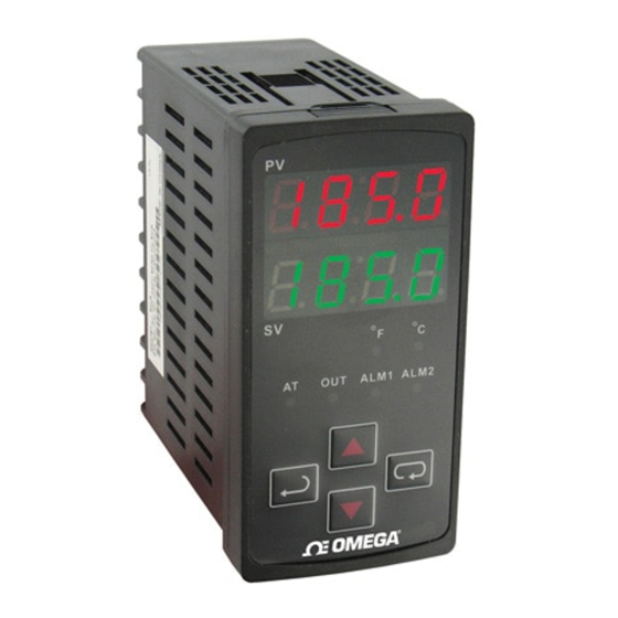
2
Display, LED, & Pushbuttons
PV
displays process value
SV
displays setpoint value.
INDEX: advances the display to the next menu item.
UP ARROW: Increments a value or changes a menu item.
DOWN ARROW: Increments a value or changes a menu item.
ENTER: stores the value or item change.
3
Model Number Identification
4
Temperature Sensor Type & Temperature Range
Input Temperature Sensor Type
Register Value
LED Display
Platinum resistance (Pt100) type3
15
Input Temperature Sensor Type
Platinum resistance (Pt100) type2
Platinum resistance (Pt100) type1
Platinum resistance (JPt100) type2
Platinum resistance (JPt100) type1
Thermocouple (TC) B type
Thermocouple (TC) S type
Thermocouple (TC) R type
Thermocouple (TC) N type
Thermocouple (TC) E type
Thermocouple (TC) T type2
Thermocouple (TC) T type1
Thermocouple (TC) J type2
Thermocouple (TC) J type1
Thermocouple (TC) K type2
Thermocouple (TC) K type1
Thermocouple (TC) L type
Thermocouple (TC) U type
Thermocouple (TC) Txk type
5
There are three modes of operation: operation, regulation and initial setting. When power is applied, the controller will
default to the operation mode. Press
the controller will switch to the initial setting mode. Pressing
forces the controller to return to the operation mode. PV/SV: Sets the temperature set point and displays the
temperature process value. Use
Setting method: While in any function mode, press
settings. Press
to save the changes. Menu items are listed below.
Regulation Mode
Auto-tuning
(Set in PID control & RUN mode)
Press
Set proportional band (Kp)
(in PID control)
Press
Set integral time (Ki)
(in PID control)
Press
Set derivative time (Kt)
(in PID control)
Press
or
P/PD control
offset (when PID control is ON and
Ki=0 set the value of PdoF. If Ki≠0, AT
(Auto-tuning will automatically set the
value of ioF.
Press
or
Heating/cooling
hysteresis
(in ON/OFF control)
Press
or
Heating/cooling
control cycle setting
(Set in PID control mode)
Press
Regulate temperature
deviation value
Press
Regulate upper-limit of
analog output value
(The setting is displayed when in
Temperature Range
analog output)
Press
0.0 ~ 100.0°C
Register Value
LED Display
Temperature Range
14
-20.0 ~ 500.0°C
13
-200 ~ 600°C
12
0.0 ~ 100.0°C
11
-20.0 ~ 400.0°C
10
100 ~ 1,800°C
9
0 ~ 1,700 °C
8
0 ~ 1,700 °C
7
-200 ~ 1,300 °C
6
0 ~ 600 °C
5
-20.0 ~ 400.0°C
4
-200 ~ 400°C
3
-20.0 ~ 400.0°C
2
-100 ~ 850°C
1
-20.0 ~ 500.0°C
0
-200 ~ 1,300°C
16
-200 ~ 850°C
17
-200 to 500°C
18
-200 to 800°C
Operation
to switch to regulation mode. If
is pressed for more than 3 seconds,
while in the regulation mode or initial setting mode,
to set the temperature set point.
to select the desired function and use
to change
Operation Mode
Initial Setting Mode
Use
to set
Set input type
temperature set point
Press
Press
Control setting RUN or STOP
Set temperature unit
(Not displayed when in analog input)
Press
Press
Upper-limit alarm 1
Set upper-limit of
(This parameter is available only when
temperature range
ALA1 function is enabled.)
Press
Press
Lower-limit alarm 1
Set lower-limit of
temperature range
(This parameter is available only when
ALA1 function is enabled.)
Press
Press
Upper-limit alarm 2
Set Control method:
(This parameter is available only when
ON/OFF, PID, or manual.
ALA2 function is enabled.)
Press
Press
Lower-limit alarm 2
Select heating or cooling
control.
(This parameter is available only when
ALA2 function is enabled.)
Press
Press
Set lock mode
Alarm 1 mode setting
Press
Press
Display and adjust output
Alarm 2 mode setting
value.
Press
Press
Communication write
function enabled/disabled
Press
Regulate lower-limit of
analog output value
(The setting is displayed when in
analog output)
Press
to return to "auto-tuning"
Parameters List
1. Operation Mode: The default mode after start-up
LED Display
Explanation
RUN/STOP: Control setting. Run (
) or Stop (
display.
ALARM 1 HIGH: Upper limit for alarm 1. (Only available when alarm is set in the
initial setting mode).
ALARM 1 LOW: Lower limit for alarm 1. (Only available when alarm is set in the
initial setting mode).
ALARM 2 HIGH: Upper limit for alarm 2. (Only available when alarm is set in the
initial setting mode).
ALARM 2 LOW: Lower limit for alarm 2. (Only available when alarm is set in the
initial setting mode).
Lock Function Setting: LoC1, LoC2, or OFF. LoC1 mode will lock all settings, LoC2
locks everything except the set point value, and OFF will not lock any settings.
Press
and
keys simultaneously, to release the lock status.
OUT: The Output value adjustment and display in manual tuning control. (Not
available in ON/OFF or Auto-tuning control).
2. Regulation Mode: Control parameters Settings
LED Display
Explanation
AT (Auto-Tuning): ON or OFF, when set ON, the execution of the auto-tuning
function in PID control mode is automatically started. (Only available when PID
control is selected in initial settings)
P (Proportional Band in PID control): Sets P value.
I (Integral Time in PID control): Sets I value.
D (Derivative Time in PID control): Sets D value.
PdoF: Offset output when P or PD control function is on. PID in initial settings is
selected and the value of Ki (Integral Time in regulation mode) is equal to zero.
ioF: Default value of integral volume when PID control is ON and the Ki (Integral
Time in regulation mode) is not equal to zero. AT function can automatically set this
parameter when PID control is active and Ki≠0.
HtS (Heating Hysteresis): Available only in ON/OFF control. Sets the value the
heating hysteresis.
CtS (Cooling Hysteresis): Available only in ON/OFF control. Sets the value the
cooling hysteresis.
HtPd: PID heating control cycle setting. Only available when a PID control is
selected in the initial settings.
ClPd: PID cooling control cycle setting. Only available when a PID control is
selected in the initial settings.
TPoF: Regulates the temperature deviation value.
CrHi: Regulates the 20mA output deviation value.
CrLo: Regulates the 4mA output deviation value.
HtS (Heating Hysteresis): Available only in ON/OFF control. Sets the value the
heating hysteresis.
3. Initial Setting Mode: Initial settings of the controller and communication parameters
LED Display
Explanation
INPUT: Select input temperature sensor type
(Please refer to the contents of the "Temperature Sensor Type and Temperature
Range" for detail)
Engineering Unit(°F or °C): Select engineering unit F or C.
T-High: Upper limit for temperature range.
T-Low: Lower limit for temperature range.
CONTROL METHOD (ON/OFF, PID, or manual tuning [
method for the set point value.
Control Action (Direct or Reverse Acting): Cooling [Cool] or heating [HEAT].
Communication address
setting
Press
Communication baud rate
setting
Press
Data length setting
Press
Parity bit setting
Press
Stop bit setting
Press
to return to "set input type"
Default
) mode on the SV
RUN
4.0°C
4.0°C
4.0°C
4.0°C
OFF
0
Default
OFF
47.6
260
41
0
0
0
0
Output
Selection:
Voltage: 4 sec.
Relay : 20 sec.
0
0
0
0
Default
PT2
°C
500.0
-20.0
]): Sets the control
PID
HEAT
Advertisement
Table of Contents

Related Manuals for Omega CN710


Summary of Contents for Omega CN710
- Page 1 -20.0 ~ 400.0°C setting Press Thank you very much for purchasing Omega Engineering CN700 Series Temperature Controller. Please read this Thermocouple (TC) B type 100 ~ 1,800°C instruction sheet before using your controller to ensure proper operation and please keep this instruction sheet handy Data length setting for quick reference.
- Page 2 Dimensions are in millimeter (inch) Execution: Display method (SV): Green color The programming execution is initiated through in the operation mode. CN710 CN730 Thermocouple: K, J, T, E, N, R, S, B, L, U, TXK Sensor type When is set to , the program will start to execute in order from the step 0 of the start pattern.
Need help?
Do you have a question about the CN710 and is the answer not in the manual?
Questions and answers