Table of Contents
Advertisement
Quick Links
Download this manual
See also:
User Manual
Advertisement
Table of Contents

Related Manuals for Omega CNi8


Summary of Contents for Omega CNi8
- Page 1 User’ s Guide MADE IN Shop on line at www.omega.com e-mail: info@omega.com iSeries info: www.omega.com/specs/iseries Temperature & Process Controller Manual CNi8, CNi8DH, CNi8DV , CNi16, CNi16D, CNi32...
- Page 2 It is the policy of OMEGA to comply with all worldwide safety and EMC/EMI regulations that apply. OMEGA is constantly pursuing certification of its products to the European New Approach Directives. OMEGA will add the CE mark to every appropriate device upon certification.
-
Page 3: Table Of Contents
TABLE OF CONTENTS Part 1: Introduction....................2 Description .................2 Safety Considerations ...............3 Before You Begin ...............4 Part 2: Setup.......................5 Front Panel .................6 Rear Panel Connections............7 Electrical Installation ..............7 2.3.1 Power Connections............7 2.3.2 Thermocouple - Input Connection........8 2.3.3 Two / Three / Four Wire RTD-Hookups ......9 2.3.4 Process Current - Wiring Hookup.......10 2.3.5 Process Voltage - Wiring Hookup .......10 2.3.6 Wiring Outputs - Wiring Hookup.........11... - Page 4 LIST OF FIGURES: Figure 2.1 Front Panel Display ................5 Figure 2.2 Rear Panel Power and Output Connector Labels......6 Figure 2.3 Rear Panel Input Connector Labels............6 Figure 2.4 Main Power Connections..............7 Figure 2.5 Thermocouple Wiring Hookup ............8 Figure 2.6 Two/Three/Four-wire RTD a) RTD-1000 ohm and 500 ohm Wiring Hookup ......9 b) RTD-100 ohm Wiring Hookup ............9 Figure 2.7...
- Page 5 NOTES, WARNINGS and CAUTIONS Information that is especially important to note is identified by following labels: • NOTE • WARNING or CAUTION • IMPORTANT • TIP NOTE: Provides you with information that is important to successfully setup and use the Programmable Digital Meter. CAUTION or WARNING: Tells you about the risk of electrical shock.
-
Page 6: Part 1: Introduction
PART 1 INTRODUCTION 1.1 Description This device can be purchased as monitor (read process value only) or as a controller. • The iSeries controller offers unparalleled flexibility in process measurement. Each unit allows the user to select the input type, from 10 thermocouple types (J, K, T, E, R, S, B, C, N and J DIN), Pt RTDs (100, 500 or 1000 Ω, with either 385 or 392 curve), DC voltage, or DC current. -
Page 7: Safety Considerations
1.2 Safety Considerations This device is marked with the international caution symbol. It is important to read this manual before installing or commissioning this device as it contains important information relating to Safety and EMC (Electromagnetic Compatibility). This instrument is a panel mount device protected in accordance with EN 61010-1:2001, electrical safety requirements for electrical equipment for measurement, control and laboratory. -
Page 8: Before You Begin
1.3 Before You Begin Inspecting Your Shipment: Remove the packing slip and verify that you have received everything listed. Inspect the container and equipment for signs of damage as soon as you receive the shipment. Note any evidence of rough handling in transit. -
Page 9: Part 2: Setup
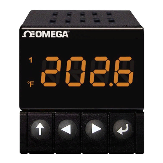
PART 2 SETUP 2.1 Front Panel Figure 2.1 Front Panel Display Table 2.1 Front Panel Annunciators Output 1/Setpoint 1/ Alarm 1 indicator Output 2/Setpoint 2/ Alarm 2 indicator °C °C unit indicator °F °F unit indicator Upper Display shows the Process Value Lower Display shows the Setpoint 1 Value Changes display to Configuration Mode and advances through menu items*... -
Page 10: Rear Panel Connections
2.2 Rear Panel Connections The rear panel connections are shown in Figures 2.2 and 2.3. 8 7 6 5 4 3 2 1 Figure 2.2 Rear Panel Power and Output Connections Figure 2.3 Rear Panel Input Connections Table 2.2 Rear Panel Connector POWER AC/DC Power Connector: All models Input Connector:... -
Page 11: Electrical Installation
2.3 Electrical Installation 2.3.1 Power Connections Caution: Do not connect power to your device until you have completed all input and output connections. Failure to do so may result in injury! Connect the main power connections as shown in Figure 2.4. Use copper conductors only for power connections Figure 2.4 Main Power Connections... -
Page 12: Thermocouple - Input Connection
2.3.2 Thermocouple The figure below shows the wiring hookup for any thermocouple type. For example, for Type K hookup, connect the yellow wire to the "2" terminal and the red wire to the "1(-)" terminal. When configuring your controller, select Thermocouple and Thermocouple Type in the Input Type menu (see Part 3). -
Page 13: Two / Three / Four Wire Rtd-Hookups
2.3.3 Two/Three/Four-Wire RTD The figures below show the input connections and input connector jumpers (shown in bold lines) required to hookup a 2-, 3- or 4-wire RTD. RTD (100Ω) 4-Wire RTD (1000/500Ω) 4-Wire RTD (100Ω) 3-Wire RTD (1000/500Ω) 3-Wire RTD (100Ω) 2-Wire RTD (1000/500Ω) 2-Wire Figure 2.6 a) RTD-1000 ohm and b) RTD-100 ohm Wiring Hookup... -
Page 14: Process Current - Wiring Hookup
2.3.4 Process Current The figure below shows the wiring hookup for Process Current 0 – 20 mA. Figure 2.7 Process Current Wiring Hookup (Internal and External Excitation) When configuring your instrument, select Process Type in the Input Type Menu (see Part 3). 2.3.5 Process Voltage The figure below shows the wiring hookup for Process Voltage 0 –... -
Page 15: Wiring Outputs - Wiring Hookup
2.3.6 Wiring Outputs This meter has two factory installed outputs. The SPDT Mechanical Relay, SPST Solid State Relay, Pulse and Analog Output Connection are shown below. Use copper conductors only for power connections Figure 2.9 a) Mechanical Relay and SSR b) Pulse and Analog Outputs Wiring Hookup Outputs Wiring Hookup... -
Page 16: Figure 2.11 Communication Output: A) Rs-232 Output - Wiring Hook Up
This device may have a programmable communication output. The RS-232 and RS-485 Output Connection are shown below. Figure 2.11 a) RS-232 Output Wiring Hookup b) RS-485 Output Wiring Hookup This device may also have an excitation output. If the Dual Display model has a Low Voltage power supply option, then excitation is not available. -
Page 17: Dual Display Color Setup
2.3.7 Dual Display Color Setup The dual display option allows the user to change the color of the upper and lower displays. To change the color of the upper display, see Section 3.2.15 (Display Color section). To change the color of the lower display follow the instructions below: The unit should be removed from the panel and opened. -
Page 18: Part 3: Operation: Configuration Mode
PART 3 OPERATION: Configuration Mode 3.1 Introduction The instrument has two different modes of operation. The first, Run Mode, is used to display values for the Process Variable, and to display or clear Peak and Valley values. The other mode, Menu Configuration Mode, is used to navigate through the menu options and configure the controller. -
Page 19: Menu Configuration
3.2 Menu Configuration It is required that you put the controller in the Standby Mode for any configuration change other than Setpoints & Alarms. Figure 3.1 Flow Chart for ID and Setpoints... -
Page 20: Id Number
3.2.1 ID Number SEE ID MENU SELECTION IN CONFIGURATION SECTION FOR ENABLE/DISABLE OR CHANGE ID CODE. If ID Code is Disabled or set as Default (0000) the menu will skip ID step to Setpoint Menu. If ID Code is set to Full Security Level and user attempts to enter the Main Menu, they will be prompted for an ID Code. -
Page 21: Setpoints
3.2.2 Set Points SETPOINT 1: Press a 1) Press a, if necessary until SP1 prompt appears. Press d 2) Display shows previous value of “Setpoint 1”. Press b & c 3) Press b and c to increase or decrease Setpoint 1 respectively. -
Page 22: Configuration Menu
3.2.3 Configuration Menu Figure 3.2 Flow Chart for Configuration Menu Enter Configuration Menu: Press a 1) Press a, if necessary, until CNFG prompt appear. Press d 2) Display advances to INPT Input Menu. Press a 3) Pressing and releasing a to scroll through all available menus of Configuration section. -
Page 23: Input Type (Thermocouple)
Input Type (Thermocouple) ENTER INPUT TYPE MENU: Press a 1) Press a, if necessary, until CNFG prompt appears. Press d 2) Display advances to INPT Input Menu. Press d 3) Display flashes T.ç , RTD or PROC (Thermocouple, RTD or Process). -
Page 24: Input Type (Rtd)
Input Type (RTD) ENTER INPUT TYPE MENU: Press a 1) Press a, if necessary, until CNFG prompt appears. Press d 2) Display advances to INPT Input Menu. Press d 3) Display flashes T.ç , RTD or PROC (Thermocouple, RTD or Process). -
Page 25: Input Type (Process)
Input Type (Process) ENTER INPUT TYPE MENU: Press a 1) Press a, if necessary, until CNFG prompt appears. Press d 2) Display advances to INPT Input Menu. Press d 3) Display flashes T.ç , RTD or PROC (Thermocouple, RTD or Process). - Page 26 ENTER READING CONFIGURATION MENU: Press a 1) Press a , if necessary, until CNFG prompt appears. Press d 2) Display advances to INPT Input Menu. Press a 3) Display advances to RDG Reading Configuration Menu. Press d 4) Display advances to DEC Decimal Point. DECIMAL POINT SUBMENU: Press d 5) Display flashes previous selection for Decimal location.
- Page 27 Reading Configuration (If Process was selected) INPUT/READING (SCALE AND OFFSET) SUBMENU: Input Voltage or Current can be converted or scaled into values appropriate for the process or signal being measured. So, a reading may be displayed, for example, in units of weight or velocity instead of in amperes or volts. The instrument determines Scale and Offset values based on two user-provided input values entered with the corresponding readings.
-
Page 28: Table 3.2 Conversion Table
Conversion number is a coefficient of conversion between input values and real full display range (10000 counts shown as 9999). See Table 3.2 below for proper conversion number. Table 3.2 Conversion Table RANGE CONVERSION NUMBER 100 mV 10000 / (100 x 1) = 100 10000 / (1000 x 1) = 10 10 V 10000 / (1000 x 10) = 1... -
Page 29: Alarm 1 Menu
3.2.6 Alarm 1 This unit is equipped with two physical outputs that can only be configured as follows: Alarm 1 & Alarm 2, Alarm 1 & Output 2, Output 1 & Alarm 2, Output 1 & Output 2, Analog Out 1 & Alarm 2, Analog Out 1 & Output 2. Analog Out available only if Analog Output Option board is factory installed. - Page 30 ALARM 1 ENABLE/DISABLE SUBMENU: Press b 5) Scroll though the available selection until ENBL displays to use Alarm 1. Press d 6) Display shows STRD stored message momentarily and then advances to ABSo only if it was changed, otherwise press a to advance to ABSo Alarm 1 Absolute/Deviation Submenu.
- Page 31 CONTACT CLOSURE SUBMENU: 11) Display flashes previous selection. Press b to N.ç. Normally Press d Closed or N.o. Normally Open. Press d 12) Display shows STRD stored message momentarily and then advances to AçTV only if it was changed, otherwise press a to advance to AçTV Active Submenu.
- Page 32 ALARM ENABLE/DISABLE AT POWER ON: Press d 15) Display flashes previous selection. Press b to ENBL enable or DSBL disable. Press d 16) Display shows STRD stored message. momentarily and then advances to ALR.L only if it was changed, otherwise press a to advance to the ALR.L Alarm 1 Low Value Submenu.
-
Page 33: Analog Output (Retransmission) Menu
3.2.7 Analog Output (Retransmission) Analog Output can be configured as Retransmission or Control outputs. In this section we will discuss Retransmission Output. This unit is equipped with two physical outputs that can only be configured as follows: Alarm 1 & Alarm 2, Alarm 1 & Output 2, Output 1 & Alarm 2, Output 1 &... - Page 34 ANALOG OUTPUT ENABLE/DISABLE SUBMENU: 5) Scroll though the available selection until ENBL displays to Press b use Analog Output Retransmission (output proportional to the input signal). Press d 6) Display shows STRD stored message momentarily and then advances to CURR or VoLT Submenu only if it was changed, otherwise press a to advance to CURR or VoLT Current/Voltage Submenu.
- Page 35 Accuracy of Analog Output board is +/-1% of FS (Full Scale) when following conditions are satisfied: 1. The input is not scaled below 1% of Input FS (10 mV @ 1 V or 0.2 mA @ 20 mA input ranges). 2.
-
Page 36: Alarm 2 Menu
3.2.8 Alarm 2 This unit is equipped with two physical outputs that can only be configured as follows: Alarm 1 & Alarm 2, Alarm 1 & Output 2, Output 1 & Alarm 2, Output 1 & Output 2, Analog Out 1 & Alarm 2, Analog Out 1 & Output 2. Analog Out available only if Analog Output Option board is factory installed. -
Page 37: Loop Break Time Menu/Field Calibration
3.2.9 Loop Break Time/Field Calibration It is required that you put the controller in the Standby Mode for any configuration change other than Set Points & Alarms. Figure 3.8 Flow Chart for Loop Break Time/Field Calibration ENTER LOOP BREAK TIME MENU: Press a 1) Press a , if necessary, until CNFG prompt appears. - Page 38 3.2.9 Loop Break Time/Field Calibration (continued) Reading Offset Adjust (C.J.) allow the user to fine tune a minor error of the transducer, however some applications may require a large offset adjust. (Displayed Process Value = Measured Process Value ± R.ADJ). R.ADJ is adjustable between -1999 to 9999. SETPOINT DEVIATION ENABLE/DISABLE SUBMENU: 13) Display advances to Setpoint Deviation ENBL Enable or DSBL Press d...
-
Page 39: Figure 3.9 Flow Chart For Output 1
3.2.10 Output 1 Alarm 1 and Output 1 or Analog Output (Retransmission) share the same contacts on the rear panel connector. If Alarm 1 or Analog Output (Retransmission) is Enabled, Output 1 is automatically Disabled. is required that you put the controller in the Standby Mode for any configuration change other... -
Page 40: Output 1 Menu
ENTER OUTPUT 1 MENU: Press a 1) Press a , if necessary, until CNFG prompt appears. 2) Display advances to INPT Input Menu. Press d Press a 3) Press a , if necessary, until Display advances to OUT1 Output 1 Menu. Press d 4) Display advances to SELF Self Submenu. - Page 41 MAXIMUM/PERCENT HIGH SUBMENU: Specify in percent, the maximum value (99) for control output. If the output is analog proportional (Current or Voltage), then the maximum voltage or current, in percent, is specified. If the output is time proportional (Relay, SSR, or Pulse), then the maximum duty-cycle, in percent, is specified.
- Page 42 ACTION TYPE SUBMENU: The error that results from the measurement of the Process Variable may be positive or negative since it may be greater or smaller than the Setpoint. If a positive error should cause the instrument output to increase (i.e. cooling), it would be called Direct Acting.
- Page 43 If Anti Integral (Anti Windup) Submenu “Enabled”, this feature allows the error term outside the proportional band to be calculated and accumulated for integration. This may be an important feature in applications where fast response time is desirable. START AUTO TUNE PID: Press d 27) Display flashes ENBL or DSBL .
- Page 44 RESET SETUP SUBMENU: Press d digit of the previous I REST Reset value. 33) Display flashes 1 Press b & c 34) Press b and c buttons to enter a new “Reset” value. Press d 35) Display shows STRD stored message momentarily and then advances to RATE only, if it was changed, otherwise press a to advance to RATE Rate Setup Submenu.
- Page 45 DAMPING FACTOR SUBMENU: Press d 42) Display flashes the previous “Damping Factor” selection. Press b 43) Scroll through the available selections: 0000 , 0001 , 0002 , 0003 , 0004 , 0005 , 0006 , 0007 . Press d 44) Display flashes STRD stored message and then advances to OUT2 only, if it was changed, otherwise press a to advance to OUT2 Output 2 Menu.
-
Page 46: Output 2 Menu
3.2.11 Output 2 Output 2 and Alarm 2 share the same contacts on the rear panel connector. If Alarm 2 is Enabled, Output 2 is automatically Disabled. is required that you put the controller in the Standby Mode for any configuration change other than Set Points &... - Page 47 ACTION TYPE SUBMENU: The error that results from the measurement of the Process Variable may be positive or negative since it may be greater or smaller than the Setpoint. If a positive error should cause the instrument output to increase (i.e. cooling), it would be called Direct Acting.
- Page 48 CYCLE TIME SUBMENU: Press d 15) Display flashes 1 digit of the previous “Cycle Time” value. Press b & c 16) Press b and c buttons to enter a new “Cycle Time” value (1 to 199 seconds). Press d 17) Display shows STRD stored message momentarily and then advances to RAMP only, if it was changed, otherwise press a to advance to RAMP Ramp Value Submenu.
-
Page 49: Ramp And Soak Menu
3.2.12 Ramp & Soak Alarm must be DISABLED if Ramp is ENABLED. is required that you put the controller in the Standby Mode for any configuration change other than Set Points & Alarms. Figure 3.11 Flow Chart for Ramp and Soak ENTER RAMP AND SOAK MENU: Press a 1) Press a , if necessary, until CNFG prompt appears. - Page 50 SOAK ENABLE/DISABLE SUBMENU: Press d 7) Display flashes ENBL or DSBL . Press b 8) Scroll through the available selections: “Enable” or “Disable”. Press d 9) Display shows STRD stored message momentarily and then advances to “Ramp Value” Submenu. Ramp & Soak provides users with the flexibility to slowly bring the Process Variable (PV) to the desired setpoint.
-
Page 51: Id Code Menu
3.2.13 ID CODE Figure 3.12 Flow Chart for ID Code ENTER ID CODE MENU: Press a 1) Press a , if necessary, until CNFG prompt appears. Press d 2) Display advances to INPT Input Menu. Press a 3) Press a , if necessary, until Display advances to ID ID Code Menu. - Page 52 ENTERING OR CHANGING YOUR (DEFAULT) ID CODE: Enter ID menu (Repeat steps from 1 to 3). Press d 10) Display advances to CH.ID Change ID Code Submenu. Press d 11) Display shows 0000 message with flashing 1 digit. If you want to change your default “ID Code” you can do it now, otherwise press a and menu will skip to FULL Full Security Submenu.
-
Page 53: Figure 3.13 Flow Chart For Communication Option
3.2.14 COMMUNICATION OPTION Purchasing the controller with Serial Communications permits an instrument to be configured or monitored from an IBM PC compatible computer using software available from the website or on the CD-ROM enclosed with your shipment. For complete instructions on the use of the Communications Option, refer to the Serial Communications Reference Manual. -
Page 54: Communication Options Menu
ENTER COMMUNICATION OPTION MENU: 1) Press a , if necessary, until CNFG prompt appears. Press a Press d 2) Display advances to INPT Input Menu. Press a 3) Press a , if necessary, until Display advances to COMM Communication Options Menu. Press d 4) Display advances to C.PAR Communication Parameters Submenu. - Page 55 STOP BIT SUBMENU: Press d 15) Display flashes previous selection for “Stop Bit”. Press b 16) Scroll through the available selections: 1-BIT , 2-BIT . Press d 17) Display shows STRD stored message momentarily and then advances to BUS.F only, if it was changed, otherwise press a to advance to BUS.F Bus Format Submenu.
- Page 56 Press d 25) Display flashes previous selection for “Echo”. Press b 26) Scroll through the available selections: NO, YES. Press d 27) Display flashes STRD stored message momentarily and then advances to STND only if it was changed, otherwise press a to advance to STND Communication Standard Submenu.
- Page 57 DATA FORMAT SUBMENU: Preformatted data can be sent automatically or upon request from the controller. Use the Data Format Submenus to determine what data will be sent in this preformatted data string. Refer to the iSeries Communications Manual for more information about the data format.
- Page 58 TEMPERATURE UNIT SUBMENU: Includes a byte in the data string to indicate whether reading is in Celsius or Fahrenheit. Press d 50) Display flashes previous selection for UNIT . Press b 51) Scroll through the available selections: NO, YES. Press d 52) Display shows STRD stored message momentarily and then advances to ADDR only, if it was changed, otherwise press a to advance to ADDR Address Setup Submenu.
-
Page 59: Display Color Selection Menu
3.2.15 DISPLAY COLOR SELECTION This submenu allows the user to select the color of the display. Figure 3.14 Flow Chart for Display Color Selection ENTER DISPLAY COLOR SELECTION MENU: Press a 1) Press a , if necessary, until CNFG prompt appears. Press d 2) Display advances to INPT Input Menu. - Page 60 ALARM 2 DISPLAY COLOR SUBMENU: Press d 11) Display flashes previous selection for “Alarm 2 Color Display”. 12) Scroll through the available selections: GRN , RED or AMBR . Press b Press d 13) Display shows STRD stored message momentarily and then momentarily shows the software version number, followed by RST Reset, and then proceeds to the Run Mode.
- Page 61 Example 3: Output 1 = Analog Output (Alarm 1 disabled), Setpoint 1 = 300, Output 2 = Relay, Setpoint 2 = 200 Alarm 1 & 2 Setup: Deviation, Band, “ALR.H” = 10 Color Display Setup: “N.CLR” = Green, “1.CLR” = Amber, “2.CLR” = Red Display Colors change sequences: GREEN •...
-
Page 62: Part 4: Specifications
PART 4 INPUT Input Types SPECIFICATIONS Thermocouple, RTD, Analog Voltage, Accuracy Analog Current ±0.5°C temp; 0.03% reading process Thermocouple Type (ITS 90) Resolution J, K, T, E, R, S, B, C, N, L 1°/0.1°; 10 µV process Thermocouple Lead Resistance Temperature Stability 100 ohm max 1) RTD: 0.04°C/°C... - Page 63 Modes DC Pulse Time and Amplitude Proportional Non-Isolated; 10 Vdc @ 20 mA Control Modes; selectable Manual or Auto PID, Proportional, Proportional Analog Output (Output 1 only) with Integral, Proportional with Non-Isolated, Proportional 0 to 10 Vdc Derivative with Anti-reset Windup and or 0 to 20 mA;...
- Page 64 EXCITATION Environmental Conditions (optional in place of Communication) • i8, i16, i32: 0 to 55°C (32 to 131°F), 24 Vdc @ 25 mA 90% RH non-condensing Not available for Low Power Option • i8DV, i8DH, i16D: 0 to 50°C (32 to 122°F), 90% RH non-condensing INSULATION Power to Input/Output...
-
Page 65: Table 4.1 Input Properties
Table 4.1 Input Properties Input Type Range Accuracy* Iron-Constantan -210 to 760°C 0.4°C -346 to 1400°F 0.7°F -270 to -160°C 1.0°C CHROMEGA ® -160 to 1372°C 0.4°C ALOMEGA ® -454 to -256°F 1.8°F -256 to 2502°F 0.7°F -270 to -190°C 1.0°C Copper-Constantan -190 to 400°C... -
Page 66: Part 5: Factory Preset Values
PART 5 FACTORY PRESET VALUES Table 5.1 Factory preset value MENU ITEMS FACTORY PRESET VALUES NOTES Set Point 1 (SP1) 000.0 Set Point 2 (SP2) 000.0 Input: Input Type (INPT) TC, type K Reading Configuration (RDG): Decimal Point (DEC.P) FFF.F Temperature unit (TEMP) °F Filter value (FLTR) - Page 67 MENU ITEMS FACTORY PRESET VALUES NOTES Ramp & Soak (RAMP) : Ramp (RAMP) Disable (DSBL) Soak (SOAK) Disable (DSBL) Ramp Value (RAMP) 00:00 Soak Value (SOAK) 00:00 ID : ID Value 0000 Full ID (FULL) Disable (DSBL) Set Point ID (ID.SP) Disable (DSBL) Communication Parameters: Baud Rate (BAUD)
-
Page 68: Part 6: Ce Approval Information
PART 6 CE APPROVALS INFORMATION This product conforms to the EMC directive 89/336/EEC amended by 93/68/EEC, and with the European Low Voltage Directive 72/23/EEC. Electrical Safety EN61010-1:2001 Safety requirements for electrical equipment for measurement, control and laboratory. Double Insulation Pollution Degree 2 Dielectric withstand Test per 1 min •... - Page 69 NOTES...
- Page 70 NOTES...
- Page 71 WARRANTY/DISCLAIMER OMEGA ENGINEERING, INC. warrants this unit to be free of defects in materials and workmanship for a period of one (1) year from the date of purchase. In addition to OMEGA’s standard warranty period, OMEGA Engineering will extend the warranty period for four (4) additional years if the warranty card enclosed with each instrument is returned to OMEGA.
- Page 72 Where Do I Find Everything I Need for Process Measurement and Control? OMEGA…Of Course! Shop on line at www.omega.com TEMPERATURE Thermocouple, RTD & Thermistor Probes, Connectors, Panels & Assemblies Wire: Thermocouple, RTD & Thermistor Calibrators & Ice Point References Recorders, Controllers & Process Monitors...
Need help?
Do you have a question about the CNi8 and is the answer not in the manual?
Questions and answers