Table of Contents
Advertisement
Quick Links
Advertisement
Table of Contents

Subscribe to Our Youtube Channel
Related Manuals for GLP KNV Series


Summary of Contents for GLP KNV Series
- Page 1 Software Version 23...
- Page 2 This manual covers fixture software version 23 © 2018-2020 German Light Products GmbH. All rights reserved. The marks ‘GLP’ and ‘German Light Products’ are trademarks registered as the property of German Light Products GmbH in Germany, in the United States of America and in other countries.
-
Page 3: Table Of Contents
Table of Contents 1. Safety ....................5 Key to symbols ................5 General safety information ............5 Electrical safety ................6 Fire safety and protection from burns........7 Eye safety ..................8 Strobe safety ................. 9 Installation safety and protection from personal injury ... 9 2. - Page 4 12. Connecting the PSU to control data ......... 51 13. Starting and stopping operation ..........52 Transportation and storage ............52 14. Cleaning and maintenance ............53 Cleaning ..................53 GLP Service and Support ............53 15. Technical specifications .............. 54 16. Dimensions ..................59...
-
Page 5: Safety
Manual contains important safety information and installation instructions that the installer and user must read. • The KNV Dot and Line User Manual, available for download from www.glp.de. The User Manual explains features and control of these fixtures. • The KNV Dot DMX Channel Index and KNV Line DMX Channel Index, available for download from www.glp.de. -
Page 6: Electrical Safety
• Check the GLP website at www.glp.de and make sure that you have the latest version of this manual. Check the PSU software version indicated on page 2 of this manual and then check the version displayed in the KNV PSU’s control panel. -
Page 7: Fire Safety And Protection From Burns
• KNV Dot and Line fixtures do not have a user-replaceable fuse. If you suspect that a fuse has blown, disconnect the fixture from the PSU and send it to a technician authorized by GLP for repair. Fire safety and protection from burns •... -
Page 8: Eye Safety
• Do not place any optical components other than KNV accessories onto the front of the fixture. • Do not stick filters, masks or other materials onto the fixture. Do not block the light output in any way. The front surface becomes hot during operation and can melt or ignite objects that are in contact with the surface. -
Page 9: Strobe Safety
• The safety of the installation is the responsibility of the installer. If in any doubt about the safety of a physical installation, consult a static engineer and seek advice from your GLP supplier before starting installation work. • KNV Dot and Line fixtures and the KNV PSU are not portable when installed. - Page 10 Do not attempt to use a product that is obviously damaged. • Do not modify the fixture or PSU in any way not described in its user documentation. • Install genuine GLP parts only. KNV Dot and Line Quick Start and Safety Manual Rev. A...
-
Page 11: Avoiding Damage
German Light Products® 2. Avoiding damage Important! Follow the directions in this section carefully, or the fixture may suffer damage that is not covered by the product warranty. General precautions Do not drop KNV Dot and Line products or expose them to mechanical stress. Do not expose products to heat (from other lighting fixtures for example). -
Page 12: Ip Rating
- Neutrik NE8MX6 to connect to data IN and THRU Ethernet ports • Use only the cables supplied by GLP for the KNV Dot and Line products to connect Dot and Line fixtures to the PSU and to each other. -
Page 13: Avoiding Damage From Dust And Airborne Particles
German Light Products® • Arrange cables so that they arrive at connectors from below. Make sure that it is impossible for water to flow down cables and accumulate at connectors. See Figure 2. If necessary, provide extra cable slack and create ‘drip loops’ before connectors. -
Page 14: Knv Dot Overview
3. KNV Dot overview Figure 3. KNV Dot overview A – White LED B – 16 x RGB LEDs C – Mounting points for optical accessories (M3 threaded holes) D – Handscrew for KNV Dot Bracket adjustment E – KNV Dot Bracket F –... -
Page 15: Knv Line Overview
German Light Products® 4. KNV Line overview Figure 4. KNV Line overview A – White LED B – 16 x RGB LEDs C – Mounting points for optical accessories (M3 threaded holes) D – Channels for KNV system connectors E – Safety cable attachment point F –... -
Page 16: Knv Psu Overview
5. KNV PSU overview Figure 5. KNV PSU overview A – Carrying handle B – Primary fuse C – Mains POWER IN connector D – Mains POWER THRU connector E – DMX IN connector, 5-pin XLR F – DMX THRU connector, 5-pin XLR G –... - Page 17 German Light Products® Figure 6. PSU mounting points L – Quarter-turn fastener attachment points for 89 mm GLP Omega Bracket M – Threaded hole for M10 mounting bolt N – Safety cable / rigging clamp attachment point (Ø13 mm) O – Safety cable attachment point P –...
-
Page 18: Features
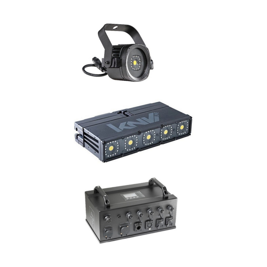
6. Features The KNV Dot and KNV Line expand GLP’s KNV Cube and Arc range to give even more flexibility in the creation of permanent and temporary dynamic lighting installations. The KNV Dot is a single-pixel source with full RGBW color mixing capability and a powerful output. -
Page 19: Installation: General
KNV Dot and Line fixtures, download the KNV Dot and Line User Manual from the GLP website at www.glp.de and read the chapter on pixel mapping. Working together with the lighting designer if necessary, you will need to plan the layout of the fixtures in the installation and plan how they will be connected to PSUs. - Page 20 Figure 8. Safety cable attachment points To secure a KNV Dot, KNV Line or KNV PSU with a safety cable: See Figure 8. Fasten the safety cable to the attachment point (arrowed) in the back of the fixture or PSU.
-
Page 21: Knv Dot Installation
Use them only as directed in this manual. Respecting all warnings on the hardware and in this manual. If you use any other installation hardware than those items listed below, check with GLP or with the hardware supplier to make sure that you do not exceed safety limits. -
Page 22: Fastening Knv Dots Together
Line up the Dots next to each other. See Figure 10. Push down on the locking button A on a GLP Slide Connector and slide the connector into the connector channels B on both Dots as shown at C. Release the locking button A so that the locking tab D engages in the cutouts in the connector channels of both Dots. -
Page 23: Flying A Single Knv Dot Using A Knv Dot Bracket
German Light Products® Figure 10. Fastening KNV Dots to each other using a GLP Slide Connector Flying a single KNV Dot using a KNV Dot Bracket To fly a single KNV Dot from a rigging truss using a KNV Dot Bracket, see Figure... -
Page 24: Flying A Single Knv Dot Using A Half-Slide Connector
To fly a single KNV Dot from a rigging truss using a GLP Half-Slide Connector, see Figure Rigging Clamp Fasten a 5/8” KNV Spigot into a GLP Half- 13-55/45/15 Slide Connector. Fasten the Half-Slide Connector into a KNV 5/8” (16 mm) Dot. -
Page 25: Flying A Column Of Knv Dots Using A Knv Dot Bracket
KNV Dot Bracket in one single, independently supported column. A column of KNV Dot fixtures that are joined together using GLP Slide Connectors and suspended vertically is considered to be one unit. The top KNV Dot must be secured by a safety cable that is approved for the total load that it secures. -
Page 26: Flying A Column Of Knv Dots Using A Half-Slide Connector
Fasten a KNV Dot under the first Dot using a GLP Slide Connector as described in ‘Fastening KNV Dots together’ on page 22. Continue adding KNV Dots as described above. Do not exceed a maximum of five (5) KNV Dots in total for any column that is suspended using a KNV Dot Bracket. If... - Page 27 ‘Securing with a safety cable’ on page 19. Fasten a KNV Dot under the first Dot Rigging Clamp by means of a GLP Slide Connector 13-55/45/15 as described in ‘Fastening KNV Dots GLP Half-Slide together’ on page 22.
-
Page 28: Flying An Array Of Knv Dots Using Half-Slide Connectors
‘Flying a column of KNV Dots using a Half-Slide Connector’ on page 26. Each time you add a new Dot to the row, fasten it to the Dot beside it using a GLP Slide Connector as described in ‘Fastening KNV Dots together’ on page 22. - Page 29 Add KNV Dots underneath the top row. Do not allow any column of Dots to exceed the limit of maximum of ten (10) Dots high in total. Each time you add a Dot, fasten it to the Dots on all sides using GLP Slide Connectors as described in ‘Fastening KNV Dots together’ on page 22.
- Page 30 Array where at least every second column is supported To create an array of multiple KNV Dots suspended from a rigging truss using GLP Half- Slide Connectors where every second column in the array and the columns at the left- and right-hand edges are independently supported: See Figure 16 on page 31.
- Page 31 German Light Products® Rigging Clamp 13-55/45/15 GLP Half-Slide Connector with 5/8” (16 mm) Spigot KNV Dot GLP Slide Connector Figure 16. KNV Dots array, every second column independently supported KNV Dot and Line Quick Start and Safety Manual Rev. A...
- Page 32 Dots on both sides using GLP Slide Connectors. Figure 17. KNV Dot array with single Dots between full columns KNV Dot and Line Quick Start and Safety Manual Rev. A...
-
Page 33: Knv Line Installation
German Light Products® 9. KNV Line installation KNV Line installation options A KNV Line may be installed as follows: Fastened into an adjustable KNV Floorstand / Hanging Bracket and standing on a stable horizontal surface. Fastened into an adjustable KNV Floorstand / Hanging Bracket that is fastened to a rigging truss at any angle using a rigging clamp or fastened to a surface or structure. -
Page 34: Knv Line Installation Hardware
Use them only as directed in this manual. Respecting all warnings on the hardware and in this manual. If you use any other installation hardware than those items listed below, check with GLP or with the hardware supplier to make sure that you do not exceed safety limits. - Page 35 German Light Products® Locks on KNV Line brackets KNV Line Floorstands, Installation Brackets and Line Brackets incorporate a spring- loaded locking mechanism: • See Figure 19. Push both locking knobs in, towards the fixture, to lock. • Push the locking knobs out, away from the fixture, to unlock.
-
Page 36: Standing A Knv Line On A Level Surface
Standing a KNV Line on a level surface You can place the KNV Line standing horizontally on a stable, flat horizontal surface. You can also place it standing vertically on the surface if you take precautions to make sure that the KNV Line cannot fall and become damaged. -
Page 37: Flying A Single Knv Line From A Rigging Truss
German Light Products® Flying a single KNV Line from a rigging truss Suspending from a KNV Line Bracket The KNV Line Bracket fastens into channels on the top and bottom of KNV Lines. It lets you fasten a rigging clamp to a KNV Line and fly the fixture from a rigging truss. To fly a KNV Line from a rigging truss using a KNV Line Bracket: See Figure 22. -
Page 38: Flying Multiple Knv Lines In A Vertical Column
Suspending from a KNV Rigging Connector As an alternative to suspension from a KNV Line Bracket, you can suspend a KNV Line fixture from a KNV Rigging Connector (see Figure 23) and half-coupler type rigging clamp. The KNV Rigging Connector fastens into one of the connector channels on the top, bottom or sides of KNV Lines. - Page 39 German Light Products® You can use KNV Module Connectors to fasten a maximum of twenty (20) KNV Line fixtures together in a single column that is suspended vertically from a rigging truss. The column may consist of KNV Line fixtures fastened to each other end-to-end or side-to- side.
- Page 40 See Figure 26. Lift up the second fixture so that the connector channels D of both fixtures are next to each other and push a KNV Module Connector C fully into the channels on both fixtures. Press the Module Connector locking knob A and twist it 90°...
-
Page 41: Flying Multiple Knv Lines In A Horizontal Row
German Light Products® Flying multiple KNV Lines in a horizontal row See Figure 27. To fly a row of KNV Line fixtures from a rigging truss: Mount the first two KNV Lines on the truss as described in ‘Flying a single KNV Line from a rigging truss’... -
Page 42: Flying An Array Of Knv Lines
You can install an array consisting of columns that are maximum ten (10) KNV Lines in height hanging vertically from GLP Half-Slide Connectors where the columns at the left- and right-hand edges of the array are independently supported and where at least every second column in the array is independently supported. -
Page 43: Knv Psu Installation
Rigging clamp and 89 mm omega bracket assembly You can use a rigging clamp and the 89 mm omega bracket from GLP to support a KNV PSU hanging downwards from a rigging truss, bar or similar support. KNV Dot and Line Quick Start and Safety Manual Rev. A... -
Page 44: Standing A Knv Psu On A Horizontal Surface
To mount a KNV PSU on a rigging truss using an omega bracket: Obtain an omega bracket with 89 mm center-to-center quarter-turn fasteners (available from GLP) and a half-coupler type rigging clamp. The bracket and clamp must be approved for the weight that they will support. -
Page 45: Mounting On A Truss Using Two Rigging Clamps And M12 Bolts
German Light Products® If there is a risk of injury or damage if the PSU falls, secure it with an approved safety cable passed through one of the holes E in the mounting plate (or through one of the PSU’s handles) and then looped around a secure anchoring point. Take up as much slack as possible in the safety cable before you fasten it. -
Page 46: Mounting On A Truss Using Custom Rigging Hardware
Figure 30. KNV PSU M10 threaded hole See Figure 30. Fasten the rigging clamp to the PSU’s mounting plate by passing the M10 bolt or screw through the rigging clamp and tightening it into the M10 hole D in the mounting plate. - Page 47 German Light Products® through one of the PSU’s handles and then looped around a secure anchoring point. Take up as much slack as possible in the safety cable before you fasten it. Figure 31. Using PSU handles for mounting KNV Dot and Line Quick Start and Safety Manual Rev. A...
-
Page 48: Ac Mains Power
AC mains power Warning! Read ‘Safety’ starting on page 5 for important safety information that you must understand before you install or operate the fixture. Check that all cables and connectors are suitable for the installation environment and application (see recommendations in ‘Avoiding damage’... -
Page 49: Connecting Multiple Knv Psus To Power In A Chain
German Light Products® connection to ground / earth and that it has an integral cable grip. Follow the cord cap / plug manufacturer’s assembly instructions. If you need to install a Neutrik powerCON TRUE1 connector on a power cable, follow the instructions given in the Support area of the Neutrik website at www.neutrik.com. -
Page 50: Connecting Fixtures To The Psu
To connect KNV Dot or Line fixtures to the PSU: Shut down power to the installation. Obtain enough KNV 6-pin ODS DC power/data extension cables from GLP to create a cable run from each PSU output to either: the first of up to five (5) interconnected KNV Dots or •... -
Page 51: Connecting The Psu To Control Data
The EtherCON ports are failsafe. This means that Art-Net or sACN data will still be forwarded even if the KNV PSU is accidentally or deliberately powered off. If you would like advice with planning and installing a DMX link, your GLP supplier will be happy to provide assistance. -
Page 52: Starting And Stopping Operation
13. Starting and stopping operation Warning! Before you apply power to the KNV installation or operate it after a blackout, make sure that nobody is looking directly into the front of the fixtures. The KNV PSU’s TRUE1 AC mains power input connector supports hot-plugging, and it... -
Page 53: Cleaning And Maintenance
Warning! There are no user-serviceable parts inside KNV fixtures or PSUs. Opening a KNV product can compromise its IP54 rating and cause damage that is not covered by the product warranty. Any service operation that requires removal of a cover must be performed by a GLP technician only. Cleaning KNV products require occasional cleaning to prevent the buildup of dust, dirt, and residue from atmospheric effects. -
Page 54: Technical Specifications
15. Technical specifications Optics, KNV Dot Total output: 2200 lumens Total LED power: 34 W Beam angle: 120° cutoff (3%) White LED LED power: 30 W Number of LEDs: 1 Lifetime: 50 000 hrs. to > 70% luminous output... - Page 55 Free-standing on horizontal surface, suspended alone or in multiple arrays from a rig or other structure, fastened to surface or structure Installation hardware KNV Dot Bracket GLP Slide Connector GLP Half-Slide Connector 13-55/45/15 Rigging Clamp 5/8” (16 mm) Spigot with screw...
- Page 56 KNV Line Mounting options Free-standing on horizontal surface directly or in adjustable floorstand, suspended alone or in multiple arrays from a rig or other structure, fastened to surface or structure Installation hardware KNV Rigging Connector KNV Module Connector KNV Floorstand / Hanging Bracket...
- Page 57 German Light Products® KNV Line DC power source: KNV PSU Max. number of fixtures per KNV PSU Data/DC power output: 1 Max. distance from PSU to last device on Data/DC power link: 50 m/164 ft. KNV PSU AC mains power: 100-240 V nominal, 50/60 Hz Power supply unit: Auto-ranging electronic switch mode Max.
- Page 58 Weight without bracket: 2.17 kg/4.78 lbs. Weight of installation bracket: 0.42 kg/0.93 lbs. KNV PSU Height: 121 mm/4.74 in. Width: 314 mm/12.36 in. Depth: 168 mm/6.59 in. Min. center-to-center distance: 320 mm/12.6 in. Weight without omega bracket: 6.82 kg/15.04 lbs.
-
Page 59: Dimensions
German Light Products® 16. Dimensions KNV Dot All dimensions are in millimeters KNV Dot and Line Quick Start and Safety Manual Rev. A... - Page 60 KNV Line All dimensions are in millimeters KNV Dot and Line Quick Start and Safety Manual Rev. A...
- Page 61 German Light Products® KNV PSU All dimensions are in millimeters KNV Dot and Line Quick Start and Safety Manual Rev. A...
Need help?
Do you have a question about the KNV Series and is the answer not in the manual?
Questions and answers