
Related Manuals for GLP Impression Series


Summary of Contents for GLP Impression Series
- Page 1 R-G-B from software version 1.41 (instruction version 1.05) e-mail: service@glp.de Internet: http://www.glp.de...
- Page 2 Notes: German Light Products GmbH instruction version 1.05...
-
Page 3: Table Of Contents
Table of content Description of Device....................4 1.1 Safety Instructions ....................5 Preparation and Installation ...................6 2.1 Mounting......................6 2.1.1 Mounting on the Floor (Upright) ............7 2.1.2 Mounting in hanging Position (Head first)..........7 2.1.3 Mounting in sidewise Position ...............8 2.2 Secure the Device ....................9 2.3 Connections......................9 2.3.1 Power Supply ..................9 2.3.2 DMX ......................9... -
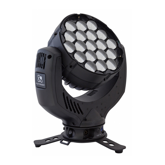
Page 4: Description Of Device
1 Description of Device 1. Moving head (actively and passively cooled) 2. Arm with various cooling vents 3. LCD-Display/Menu (data entry) 4. Base with various connectors and Camlock mounting system base side 1 5. Power On/Off 6. DMX- Output (3 pole) 7. -
Page 5: Safety Instructions
Safety cables or clamps/hooks can increase the risk of an accident. 8. Repair-, maintenance- and installation work shall be done by qualified or GLP certified staff only. You need to pay attention to the common rules of technology that are not explicit mentioned in this manual. -
Page 6: Preparation And Installation
2 Preparation and Installation 2.1 Mounting N is fully operational whether it hangs or is mounted to the wall. It can also be operated while standing on the floor. Keep a safety distance of 0.5 m towards any easily inflammable materials (decoration etc.). Pay attention to the regulations of: BGV C1 (former VBG 70) and DIN VDE 0711-217. -
Page 7: Mounting On The Floor (Upright)
1x M10 (length max.16mm) 2x Camlock quick release fasteners front side of the fixture 2.1.1 Mounting on the Floor (Upright) To operate the N in an upright position, please use the dedicated tripod which is mounted to the bottom side of the system. It is fixed with fasteners called Camlock quick-release connectors. -
Page 8: Mounting In Sidewise Position
M10x16 2.1.3 Mounting in sidewise Position To operate the N in a sidewise position, please use an addition mounting bar. Also this is fixed by two Camlock quick-release connectors. Two half-couplers (clamps) are now used to mount the system to a standard truss bar. This technique is necessary to cope with the torque which accrues in this mounting position. -
Page 9: Secure The Device
without mounting bar 2.2 Secure the Device Regardless of the mounting method of the N you'll have to use a stipulated safety wire. Therefore you have to pull the safety wire through to two provided holes on the bottom side of the system and connect it with the truss- support. -
Page 10: The Menu Field
3 The Menu Field You’ll find the control board on the side part of the arm. It allows you to make all necessary adjustments of the . With the Mode-key you get into the main menu. Afterwards you can navigate through the menu with the Up/Down-keys. - Page 11 Temperature Indicates the arm temperature Temperature Indicates the head temperature Head Lamp Off if Defines whether the last DMX signal is stored or the DMX off lamp is switched OFF in case of signal interruption Position Automatically position feedback (correction) for Feedback Pan/Tilt movement White...
-
Page 12: Dmx Channel Selection (Dmx Protocol)
4 DMX Channel Selection (DMX Protocol) Normal- Mode 14 DMX channels Channel Function Time and Value 1) PAN- 0 .. 660° min. 3,2 s 0..255 00..FF 0..100 coarse 2) PAN-fine High- Pos ... High- Pos + 2,6° (16 Bit) 0..255 00..FF 0..100 0 .. - Page 13 Channel Function Time and Value 90° 10..11 0A..0B 180° 12..13 0C..0D 270° 14..15 0E..0F 0° 16..17 11..11 90° 18..19 12..13 180° 20..21 14..15 270° 22..23 16..17 0° 24..25 18..19 90° 26..27 1A..1B 10,4 180° 28..29 1C..1D 11,2 270° 30..31 1E..1F TILT size / phase see also PAN 32..63...
- Page 14 Channel Function Time and Value Color 05 - Dark Lavender 40..47 28..2F 16..18,5 Color 06 - Amber 48..55 30..37 19..21,5 Color 07 - Deep Golden 56..63 38..3F 22..24,5 Color 08 - Dark Blue 64..71 40..47 25..27,5 Color 09 - Pink 72..79 48..4F 28..30,5...
-
Page 15: Maintaining And Cleaning The I M P R E S S I O N
Channel Function Time and Value 12) Dimmer- Dimmer (0% - 100%) 0..255 0..FF 0..100 coarse 13) Dimmer- Dimmer - High 0..255 0..FF 0..100 fine 5 Maintaining and Cleaning the N is a system of very low maintenance. It is only necessary to clean the air in- and outlets as well as the optical LED lenses from time to time. -
Page 16: Technical Specifications
6 Technical Specifications Power supply Power consumption 350 VA (Watt) Power Input ~100-240 V AC, 50-60 Hz (wide range input) Micro-fuse 5x20 mm, T 4A Fuse protection Operational Parameters Max. Ambient 45°C (integrated overheating switch) Temperature Mounting Position Any (see chapter mounting) Lighting System - Additive Color mixing LED Type 90x Luxeon K2 High-power- LEDs... -
Page 17: Index
7 Index Mounting............6 Mounting in hanging Position......7 BGV C1............6 Mounting in sidewise Position......8 Mounting on the Floor ........7 Camlock............7 Circumference ..........15 Normal- Mode ..........12 Cleaning............15 Compressed- Mode ........13 Optical parts ..........15 Danger of BURNING ........5 Description of Device........4 Pan- Movement.......... - Page 18 German Light Products GmbH instruction version 1.05...
Need help?
Do you have a question about the Impression Series and is the answer not in the manual?
Questions and answers