Table of Contents
Advertisement
Quick Links
Advertisement
Table of Contents

Summary of Contents for Advanced Navigation Motus
- Page 1 Motus Reference Manual...
-
Page 2: Table Of Contents
Motus Reference Manual Page 1 of 146 Version 1.1 29/11/2019 Table of Contents 1 Revision History......................8 2 Firmware Changelog....................9 3 Hardware Changelog....................10 4 Introduction......................11 5 Foundation Knowledge..................... 12 5.1 GNSS......................... 12 5.2 INS........................12 5.3 GNSS/INS......................12 5.4 AHRS......................... - Page 3 11.4.2 Velocity Heading..................40 11.4.3 External Heading..................40 11.5 Magnetics......................40 11.5.1 2D Magnetic Calibration................41 11.5.1.1 Using the Motus Manager Software...........41 11.5.1.2 Using the Packet Protocol..............41 11.5.2 3D Magnetic Calibration................42 11.5.2.1 Using the Motus Manager Software...........42 11.5.2.2 Using the Packet Protocol..............42 11.5.3 Automatic Magnetic Calibration...............42...
- Page 4 12.4.3 Linux......................48 12.5 Main View......................50 12.5.1 Serial Port....................50 12.5.2 Attitude Indicator..................50 12.5.3 Status Indicator..................50 12.5.3.1 Motus Status Indicator...............51 12.5.3.2 Fix Indicator..................51 12.5.3.3 Satellites Table.................. 51 12.5.4 3D Map..................... 51 12.5.5 3D Map Controls..................51 12.5.5.1 Reset View..................
- Page 5 Motus Reference Manual Page 4 of 146 Version 1.1 29/11/2019 13.2.3 Basic Connection..................77 13.3 Recommended Footprint.................77 13.4 OEM Power Supply................... 79 13.5 OEM Pin Protection..................79 14 OEM Development Board..................80 14.1 Serial UART to USB Converter................81 14.2 Dual RS232 Transceiver...................81 14.3 GPIO Header and Status LEDs.................81...
- Page 6 15.4.40 Odometer Direction, Forward High............96 15.4.41 Reverse Alignment, Forward Low............96 15.4.42 Reverse Alignment, Forward High............96 15.4.43 Zero Angular Velocity Input..............96 16 Advanced Navigation Packet Protocol..............97 16.1 Data Types....................... 97 16.2 Packet Structure....................97 16.2.1 Header LRC....................98 16.2.2 Packet ID....................98 16.2.3 Packet Length...................
- Page 7 Motus Reference Manual Page 6 of 146 Version 1.1 29/11/2019 16.9.8 Quaternion Orientation Standard Deviation Packet........111 16.9.9 Raw Sensors Packet................111 16.9.10 Raw GNSS Packet.................112 16.9.10.1 Raw GNSS Status................112 16.9.11 Satellites Packet................... 113 16.9.12 Detailed Satellites Packet..............113 16.9.12.1 Satellite Systems................114 16.9.12.2 Satellite Frequencies..............114...
- Page 8 Motus Reference Manual Page 7 of 146 Version 1.1 29/11/2019 16.10.2.2 Packet Period.................128 16.10.3 Baud Rates Packet................128 16.10.4 Installation Alignment Packet...............129 16.10.4.1 Alignment DCM................129 16.10.5 Filter Options Packet................130 16.10.5.1 Vehicle Types................. 131 16.10.6 Advanced Filter Parameters Packet............131 16.10.7 GPIO Configuration Packet..............131 16.10.7.1 GPIO1 Functions................132...
-
Page 9: Revision History
Motus Reference Manual Page 8 of 146 Version 1.1 29/11/2019 Revision History Version Date Changes 29/11/2019 Updated firmware changelog 2 Updated hardware changelog 3 Updated dynamic pin functions table 15.4 Updated GPIO configuration packet 16.10.7 Added pressure depth transducer deprecated input function 15.4.16... -
Page 10: Firmware Changelog
Motus Reference Manual Page 9 of 146 Version 1.1 29/11/2019 Firmware Changelog Version Date Changes 28/11/2019 Improvements to raw sensor calibration algorithm Prevents fast temperature variations from introducing digital noise into accelerometer values which was regression from firmware version 1.4... -
Page 11: Hardware Changelog
Motus Reference Manual Page 10 of 146 Version 1.1 29/11/2019 Hardware Changelog Version Date Changes 16/07/2018 Internal manufacturing improvements No noticeable changes for customers 07/09/2017 Improvements to ADC synchronisation results in slightly improved performance under high dynamics 05/10/2016 Internal manufacturing improvements... -
Page 12: Introduction
Version 1.1 29/11/2019 Introduction Motus is a miniature ultra high accuracy MEMS IMU. It features some of the highest accuracy MEMS accelerometers and gyroscopes currently available combined with magnetometers. Motus is fully calibrated for all sensor errors over a wide temperature range and can be software upgraded to AHRS or INS functionality. -
Page 13: Foundation Knowledge
29/11/2019 Foundation Knowledge This chapter is a learning reference that briefly covers knowledge essential to understanding Motus and the following chapters. It explains the concepts in simple terms so that people unfamiliar with the technology may understand it. GNSS GNSS stands for global navigation satellite system. A GNSS consists of a number of satellites in space that broadcast navigation signals. -
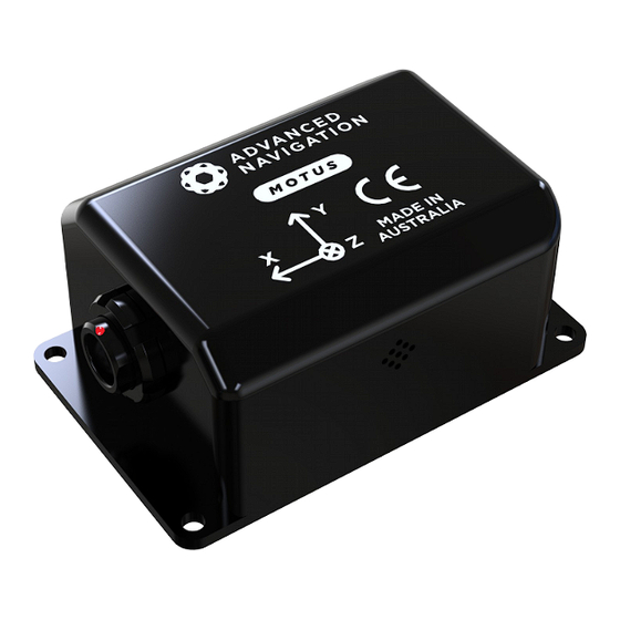
Page 14: The Sensor Co-Ordinate Frame
Z axis pointing down through the base of the unit and the Y axis pointing out of the starboard side. Illustration 1: Motus axes Illustration 2: First right hand rule When installed in an application the X axis should be aligned such that it points forwards and the Z axis aligned so that it points down when level. -
Page 15: Rotation Order
This can be hard for some people to grasp at first and is often best learned experimentally by rotating Motus with your hand whilst watching the orientation plot in real time on the computer. - Page 16 Motus Reference Manual Page 15 of 146 Version 1.1 29/11/2019 Illustration 4: Latitude and longitude represented visually to describe a position Illustration 5 shows latitude and longitude on a map of the world.
-
Page 17: Ned Co-Ordinate Frame
Motus Reference Manual Page 16 of 146 Version 1.1 29/11/2019 Equator Illustration 5: World map showing latitudes and longitudes Latitude and longitude give the 2D point on the surface of the Earth. These are combined with height to give the 3D position on the Earth. -
Page 18: Ecef Co-Ordinate Frame
Earth. ECEF is an alternative to the geodetic co-ordinate frame. It is represented by the three axes X, Y and Z which are presented graphically in Illustration 6. ECEF positions can be retrieved from Advanced Navigation products however the geodetic system is used as the default. -
Page 19: Rugged Evaluation Kit
4. Click the connect button in Motus Manager. 5. The various windows in Motus Manager can be used to view the real time data. 6. To view the data logs, click disconnect in Motus Manager. In the Tools menu, select Log Converter and press Convert. -
Page 20: Oem Evaluation Kit
1. Mount the Motus OEM unit onto the Motus OEM development board and screw it down. 2. Plug one end of the USB cable into the Motus development board and the other end into your computer. 3. Download the Motus Manager software from the Motus page of the Advanced Navigation website. - Page 21 Motus Reference Manual Page 20 of 146 Version 1.1 29/11/2019 same folder as the Motus Manager software.
-
Page 22: Part Numbers And Ordering Options
AHRS and INS upgrade licenses can be purchased separately, see section 8.3 Table 5: Standalone unit part numbers Software License Upgrades These license upgrades can either be ordered with the unit or purchased later and installed in the field using Motus Manager. -
Page 23: Accessories
Accessories Part Number Description Notes A503-SDC20796 ODU plug to FTDI Motus rugged ODU plug with 2 metres of USB cable cable to FTDI USB plug, see section 9.12 A503-SDC20740-2M ODU plug with Motus rugged ODU plug with 2 metres of 2m cable unterminated cable, see section 9.11... -
Page 24: Specifications
Motus Reference Manual Page 23 of 146 Version 1.1 29/11/2019 Specifications Mechanical Drawings Illustration 11: Motus rugged mechanical drawings... -
Page 25: Navigation Specifications
Illustration 12: Motus OEM mechanical drawings Navigation Specifications Motus can be upgraded to full AHRS or INS capability through a software license upgrade. As an INS it can be interfaced to any of the leading brands of GNSS receivers to create an OEM GNSS/INS solution. When using a Trimble MBTwo receiver, for... -
Page 26: Sensor Specifications
Motus Reference Manual Page 25 of 146 Version 1.1 29/11/2019 Parameter Value Horizontal Position Accuracy 0.8 m Vertical Position Accuracy 1.5 m Horizontal Position Accuracy (RTK) 0.008 m Vertical Position Accuracy (RTK) 0.015 m Velocity Accuracy 0.007 m/s Roll & Pitch Accuracy 0.05 °... -
Page 27: Rugged Communication Specifications
Motus Reference Manual Page 26 of 146 Version 1.1 29/11/2019 Rugged Communication Specifications Parameter Value Interface RS232 (RS422 optional) Primary and Auxiliary Port Speed 2400 to 2 M baud GPIO Port Speed 2400 to 250 K baud Protocol AN Packet Protocol... -
Page 28: Oem Hardware Specifications
Motus Reference Manual Page 27 of 146 Version 1.1 29/11/2019 Dimensions (excluding tabs) 42 x 55 x 30 mm Dimensions (including tabs) 42 x 67 x 30 mm Weight 72 grams Table 12: Rugged hardware specifications OEM Hardware Specifications Parameter... -
Page 29: Rugged Electrical Specifications
Motus Reference Manual Page 28 of 146 Version 1.1 29/11/2019 Rugged Electrical Specifications Parameter Minimum Typical Maximum Power Supply Input Supply Voltage 36 V Input Protection Range -60 V 60 V RS232 Tx Voltage Low -5.7 V -5 V Tx Voltage High 6.2 V... -
Page 30: Power Consumption
Power supply and signal connections are made through a ODU Mini-Snap Series B 9 pin connector. The ODU part number is S30B0SP09MCC00-5000. The connector provides a reliable and rugged connection to Motus under demanding conditions and is rated to IP68 in the mated condition. Plugs are supplied with 2 metres of unterminated shielded cable with an outer protective jacket, part number A503-SDC20740-2M. -
Page 31: Rugged Evaluation Kit Usb Cable
9.12 Rugged Evaluation Kit USB Cable The evaluation kit is supplied with a 2 metre cable with a Motus ODU plug on one end and an overmoulded RS232 to USB converter on the other end, please see Illustration 15. The cable is the same 9 wire cable supplied with unterminated ODU cables and all 9 wires are connected on the ODU end. -
Page 32: Optional Rugged Breakout Cable
Advanced Navigation offers a pre-terminated breakout cable for access to all of Motus's pins. All external signal and power connections are provided with 2m of cable. The interface cable is provided with industry standard 9 pin DSUB connectors for each of the two RS232 communication channels and GPIO pins. -
Page 33: Sensor Calibration
9.15 Serial Number The serial number can be inspected by using the Device Information dialogue in the Motus Manager software, see section 12.7.1. The primary serial number label is... - Page 34 Version 1.1 29/11/2019 located inside the enclosure and is accessible only by Advanced Navigation technicians. The secondary serial number label is located on the outside rear of the enclosure with the serial number encoded in a 2D data matrix bar code to assist customers in tracking their units, see Illustration 17.
-
Page 35: Installation
10.2.1 Alignment The easiest way to align Motus is by installing it with the sensor axes aligned with the vehicle axes. This means that the X axis points forward towards the front of the vehicle and the Z axis points down towards the ground. -
Page 36: Mounting Plate
10.4 Power Supply A high level of power supply filtering has been built into Motus to allow for reliable operation in demanding environments. Motus contains a fully isolated power supply and has separate grounds for power and signal to ensure that power supply noise does not corrupt communications or cause ground loops with other equipment. -
Page 37: Odometer
Factory VSS Signal Most road cars since 1980 contain a VSS (vehicle speed sensor) signal that can be wired directly into one of Motus’s GPIO pins. The vehicle should be taken to an automotive electrician to perform the work. To setup the odometer, the appropriate GPIO pin should be set to odometer input using Motus Manager, see section 12.8.6. - Page 38 Motus Reference Manual Page 37 of 146 Version 1.1 29/11/2019...
-
Page 39: Aftermarket Wheel Speed Sensor
Radar Speed Sensor For applications requiring high performance in harsh conditions where aftermarket wheel speed sensors are not feasible, a radar speed sensor is recommended. Advanced Navigation recommends radar speed sensors from Stalker or GMH Engineering. Illustration 21: Radar speed sensor... -
Page 40: Magnetics
1. Try to find a mounting point with less vibration. 2. Motus can be mounted on top of a small flat piece of rubber. Please note that this may cause small changing orientation errors due to flexing of the rubber. -
Page 41: Ins And Ahrs Operation
Once orientation initialisation is complete, the roll, pitch and angular velocity values will be valid. When Motus starts up, it assumes that it can be in any orientation. To determine it's orientation it uses the accelerometers to detect the gravity vector. Whilst this is occurring, if there are random accelerations present, these can cause an incorrect orientation to be detected. -
Page 42: Heading Initialisation
A next generation backup battery system within Motus provides the hot start ability for more than 48 hours without power. When Motus hot starts it assumes that it is in the same state it was when it lost power and begins navigating from that position. When the GNSS achieves it's first fix, if this position deviates from the hot start position, Motus will jump to the new position without causing any side effects to the filter. -
Page 43: Time
11.3 Time Motus was designed to provide a highly accurate time reference. When a GNSS fix is available Motus's time is accurate to within 50 nanoseconds. When a GNSS fix is lost, Motus's time accuracy typically remains within 10 microseconds over extended time periods. -
Page 44: Magnetic Calibration
For example if Motus is installed in a car and the car drives over a large piece of magnetised steel, this will be compensated for. Another example is driving through a tunnel which is built from heavily reinforced concrete. -
Page 45: Using The Packet Protocol
2. After power on wait 5 minutes for the temperature and filter to stabilise. 3. Open Motus Manager and connect to the device. Ensure that the device has either a GNSS fix or the position has been manually entered in the Manual Initialisation window before proceeding. -
Page 46: Automatic Magnetic Calibration
2D or 3D calibration it can give the best results from magnetic heading. Every time Motus is powered on in a cold start (48 hours without power) the automatic calibration is reset. The automatic magnetic calibration starts operating when Motus is travelling at a speed over 5 m/s with a GNSS fix and velocity heading turned on. -
Page 47: Vehicle Profiles
11.8 Odometer Pulse Length For Motus to use a wheel speed sensor or odometer input, it must know the pulse length of the signal. The pulse length is the distance in metres between low to high transitions of the signal. The odometer pulse length can either be entered manually or automatically calibrated by Motus. -
Page 48: Motion Analysis
Heave works without a GNSS fix, however best heave performance is achieved when Motus has a GNSS fix. By default Motus provides heave from the point at which the Motus unit is mounted, however it can provide heave at four different offset points on the ship. To set the heave offsets, use the Reference Position Offsets dialogue in Motus Manager, see section 12.8.9. -
Page 49: Water
When un-mating the connectors if the Motus Rugged unit is dirty or dusty, the dirt should be rinsed off with fresh water first and then dried off. This is to prevent dirt or dust entering the connectors which can cause them to fail. -
Page 50: Motus Manager
Page 49 of 146 Version 1.1 29/11/2019 Motus Manager Motus Manager is a software tool provided by Advanced Navigation for logging, testing, display and configuration of Motus. It is designed to be simple and easy to use. Illustration 23: Screenshot of Motus Manager... -
Page 51: Software Changelog
If the serial port does not show up when you plug in your Motus USB device, you may need to install the drivers from http://www.ftdichip.com/Drivers/VCP.htm. If you experience a blue screen of death whilst using Motus Manager, this is typically a problem associated with older FTDI drivers. -
Page 52: Linux
Motus Reference Manual Page 51 of 146 Version 1.1 29/11/2019 the FTDI driver. To resolve this problem the latency of the driver should be reduced by going to control panel → system → device manager → ports and right click on the USB serial port, then click properties. - Page 53 Motus Manager is able to run on the OpenJDK JRE but it uses significantly more system resources than when it is running on the Oracle JRE.
-
Page 54: Main View
12.5.1 Serial Port The Serial Port list is used to connect to Motus. You should select a serial port and baud rate and click connect. The default baud rate of Motus is 115200. The Connection Indicator displays whether there is communication with a Motus unit. -
Page 55: Motus Status Indicator
12.5.4 3D Map The 3D map shows Motus's position on the Earth as well as a red trail of position history. When the filter initialises the map will automatically reset the view to Motus's location. To move the camera click and drag on the map. To zoom in and out use the scroll wheel. -
Page 56: View
Version 1.1 29/11/2019 Illustration 26: Screenshot showing log file and log conversion folder 12.7 View The View menu contains a number of different options for viewing data from Motus. Illustration 27: Screenshot of Motus Manager View menu 12.7.1 Device Information... -
Page 57: Status
Page 56 of 146 Version 1.1 29/11/2019 Illustration 28: Screenshot of Motus Manager Device Information dialogue 12.7.2 Status Status shows Motus's complete status as contained in the system state packet detailed in section 16.9.1.1. Illustration 29: Screenshot of Motus Manager Status dialogue... -
Page 58: Satellites
Motus Reference Manual Page 57 of 146 Version 1.1 29/11/2019 12.7.3 Satellites Satellites shows detailed information on the satellites that Motus's GNSS receiver is tracking. Elevation and azimuth are in units of degrees. Illustration 30: Screenshot of Motus Manager Satellites dialogue... -
Page 59: Raw Sensors
Motus Reference Manual Page 58 of 146 Version 1.1 29/11/2019 12.7.4 Raw Sensors Raw sensors shows the temperature calibrated raw sensor values. Illustration 31: Screenshot of Motus Manager Raw Sensors dialogue... -
Page 60: Orientation
Motus Reference Manual Page 59 of 146 Version 1.1 29/11/2019 12.7.5 Orientation Orientation shows Motus's orientation, angular velocity and orientation error. Illustration 32: Screenshot of Motus Manager Orientation dialogue... -
Page 61: Position
Page 60 of 146 Version 1.1 29/11/2019 12.7.6 Position Position shows Motus's position and position error. Latitude and longitude are converted to North and East metres from a reference point that can be reset. Illustration 33: Screenshot of Motus Manager Position dialogue... -
Page 62: Velocity And Acceleration
Motus Reference Manual Page 61 of 146 Version 1.1 29/11/2019 12.7.7 Velocity and Acceleration Velocity and Acceleration shows Motus's velocity, acceleration and g-force. Illustration 34: Screenshot of Motus Manager Velocity and Acceleration dialogue... -
Page 63: Model
Motus Reference Manual Page 62 of 146 Version 1.1 29/11/2019 12.7.8 3D Model This dialogue shows a real-time 3D model of Motus's orientation. Illustration 35: Screenshot of Motus Manager 3D Model dialogue... -
Page 64: Communications Statistics
Page 63 of 146 Version 1.1 29/11/2019 12.7.9 Communications Statistics This dialogue shows statistics on the data packets received from Motus and can be useful in diagnosing signal integrity problems. Illustration 36: Screenshot of Motus Manager Communications Statistics dialogue 12.7.10... -
Page 65: Configuration
12.8.1 Configuration Export The Configuration Export dialogue can be used to export all Motus settings to a file. This file can be imported at a later date or on other units. This is useful to restore a unit to preset configuration at a later date or for batch configuration of multiple units. -
Page 66: Filter Options
Page 65 of 146 Version 1.1 29/11/2019 12.8.2 Filter Options For most applications the default filter options should be used and only the vehicle profile set. If in doubt please contact support@advancednavigation.com. Illustration 40: Screenshot of Motus Manager Filter Options dialogue... -
Page 67: Packet Rates
These two packets need to be enabled for the data graphs to update in Motus Manager. Other state packets can be enabled as required. Please see the Packet Summary table in section 16.7 for a list of all packets. -
Page 68: Alignment Configuration
12.8.4.1 Alignment Offset If Motus is installed into the vehicle with the X axis pointing forwards and the Z axis pointing down, then no alignment offset is required and the roll, pitch and heading offset values can remain at the factory defaults of zero. -
Page 69: Gnss Antenna Offset
Version 1.1 29/11/2019 12.8.4.2 GNSS Antenna Offset The GNSS antenna offset is measured from the centre of the Motus unit to the centre of the antenna in the body co-ordinate frame (X positive forward, Z positive down). 12.8.4.3 Odometer Offset... -
Page 70: Gpio Configuration
Please note that GPIO pins function at RS232 levels for data functions and 0 to 5 volt levels for all other functions. The internal hardware automatically reconfigures based upon the selected function. Illustration 44: Screenshot of Motus Manager GPIO configuration dialogue 12.8.7... -
Page 71: Reset
Motus unit. This can be offset to a different position on the ship by entering the offset value from the centre of the Motus unit to the desired position in the body co-ordinate frame (X positive forwards, Z positive down). -
Page 72: Gpio Output
Version 1.1 29/11/2019 12.8.10 GPIO Output The GPIO Output configuration dialogue allows the user to configure the output rates for the GPIO and Auxiliary RS232 data functions NMEA, TSS and PASHR. Illustration 48: Screenshot of Motus Manager GPIO Output configuration dialogue... -
Page 73: Manual Initialisation
Version 1.1 29/11/2019 12.8.11 Manual Initialisation This dialogue can be used to manually initialise Motus when a GNSS fix is not available. Setting the position will initialise the navigation filter. Setting the heading will initialise the heading. Illustration 49: Screenshot of... -
Page 74: Magnetic Calibration
The Magnetic Calibration dialogue allows the user to perform magnetic calibration as well as view and modify the magnetic calibration values. The actual magnetic calibration is performed inside the Motus unit. This dialogue does not have any smarts, it is just a control and display interface. -
Page 75: Firmware Update
This tool allows the user to convert Motus log files into various standard formats that are readable by many programs. The position offset values can used to project the exported position to a point other than the centre of the Motus unit. For most users these values should be left at zero. -
Page 76: Network Connect
Network Connect The Network Connect dialogue allows Motus Manager to make a connection to Motus over a TCP/IP network rather than the default serial port connection. This allows Motus to be used with ethernet to serial converters. Advanced Navigation recommends Lantronix ethernet to serial converters. -
Page 77: Oem Integration
OEM is connected to target PCB, four M1.6 screws and washers and nuts on the back side of the target PCB are used to hold the Motus OEM in place, please see Illustration 55. The length of the M1.6 screws will be depended on the thickness of the target PCB. -
Page 78: Oem Electrical Connector
Motus OEM and the target board. It should be noted that this connector is not designed for the Motus OEM to be plugged in whilst power is applied to the user's PCB and connector mating cycles should not exceed 50 cycles to ensure connector reliability. - Page 79 Motus Reference Manual Page 78 of 146 Version 1.1 29/11/2019 Illustration 58: Motus OEM connector pin numbering...
-
Page 80: Interoperability With Different Voltage Systems
13.2.2 Reset Line The reset line is internally pulled high on Motus OEM. This pin must be left floating for normal operation. If a user wishes to reset Motus OEM the pin can be pulled low externally to force a reset. It is important that this signal is not driven high under any circumstances as it will prevent the Motus OEM from functioning correctly. -
Page 81: Basic Connection
Version 1.1 29/11/2019 13.2.3 Basic Connection Please see Illustration 59 for the basic electrical connections required by Motus OEM. Illustration 59: Motus OEM basic electrical connections 13.3 Recommended Footprint The footprint for Motus OEM incorporates four through-hole for M1.6 screws to pass through and 20 SMD pads for the board to board connector. - Page 82 "Keep Out" Area SC ALE 2:1 Illustration 61: Recommended footprint for Motus OEM PCB footprint files are provided in the documentation section of the website. Please contact Advanced Navigation support if you have any issues or to verify your footprint is correct.
-
Page 83: Oem Power Supply
13.4 OEM Power Supply A high level of power supply filtering has been built into Motus OEM, however it is still recommended that the power supply be free of significant noise. The unit is only rated for inputs from 4.5 V to 5.5 V, exceeding 6 V can cause permanent damage to the unit. -
Page 84: Oem Development Board
The OEM development board is a configurable PCB that provides developers with easy access to all of the features of the Motus OEM unit through a number of different interfaces. Illustration 63 shows an image of the OEM development board. -
Page 85: Serial Uart To Usb Converter
Motus OEM unit via RS232. The SP3222EU allows baud rates of up to 1000000 baud. Channel 1 of the SP3222EU is for use with the primary serial port on the Motus OEM unit and Channel 2 of the SP3222EU is for use with GPIO 3 (RS232 TX 2) and GPIO 4 (RS232 RX 2). -
Page 86: Configuration Switches
Failure to protect the signals may result in damage to Motus OEM. Other pins on the GPIO header include a regulated 3.3V supply from Motus that can supply up to 50mA, Motus' reset line and the external voltage input (VEXT). -
Page 87: Primary Serial Port To Usb
Motus Reference Manual Page 86 of 146 Version 1.1 29/11/2019 Illustration 66: Configuration switches in their default position Switch Default Function Power on RS232 transceiver. When the RS232 transceiver is powered on GPIO 3 and 4 will be connected to RS232 TX 2 and RS232 RX2 respectively. It will no longer be possible to use GPIO 4 in a TTL level mode. -
Page 88: Primary Serial Port And Gpio 3 & 4 To Gpio Header At Ttl Levels
Motus Reference Manual Page 87 of 146 Version 1.1 29/11/2019 14.4.2 Primary Serial Port to RS232 1 and GPIO 3 & 4 to RS232 2 Illustration 68: Switch positions for primary serial port to RS232 1 and GPIO 3 & 4 to RS232 2 14.4.3... -
Page 89: Power Source
GPIO header of RS232 header and can be any voltage between 4V and 36V. Please refer to the Motus OEM Reference Manual for full power supply requirements. The power source is selected by a three way switch, please see Illustration 70 and Illustration 71. - Page 90 Motus Reference Manual Page 89 of 146 Version 1.0 29/11/2019...
- Page 91 Motus Reference Manual Page 90 of 146 Version 1.0 29/11/2019...
-
Page 92: Interfacing
External sources of position, velocity and/or heading can be integrated into Motus's filter solution. The data can be sent to Motus in the ANPP format over the primary port or through one of the GPIO pins in a number of different formats. If using the ANPP, please use Table 22 below to find the relevant section. -
Page 93: Gpio Pins And Auxiliary Rs232
2400 to 250 K baud. The auxiliary serial baud rate can be configured anywhere from 2400 to 2 M baud. Changes to these baud rates can be made by using the Baud Rates dialog box in Motus Manager (see section 12.8.5) or the Baud Rates Packet (see section 16.10.3). - Page 94 Motus Reference Manual Page 93 of 146 Version 1.1 29/11/2019 Function Type GPIOs Auxiliary RS232 Disable Magnetometers Digital Input Receive Set Zero Orientation Alignment Digital Input Receive System State Packet Trigger Digital Input Receive Raw Sensors Packet Trigger Digital Input...
-
Page 95: 1Pps Output
15.4.4 Zero Velocity Input When using this function, a high state indicates to Motus that it is stationary. The low state indicates that the vehicle is not stationary. Use of this function can significantly improve drift performance when a GNSS signal is not available. -
Page 96: Nmea Input
This function outputs a configurable combination of NMEA messages at up to 50 Hz. The messages output and the output rate can be configured using the GPIO Output configuration dialogue in Motus Manager. A complete list of available messages can be found in section 16.10.14. -
Page 97: Novatel Gnss Input
This function accepts a digital input. The input is normally low and a transition from low to high causes Motus to set it's alignment so that the current orientation is zero. Due to the risk of exhausting the flash cycles, the change is not permanent and will disappear on reset. -
Page 98: Pressure Depth Transducer
9 and 34 at 1 to 2Hz. 15.4.18 u-blox GNSS Input This function is designed for interfacing Motus with a u-blox GNSS receiver. It accepts data in the u-blox binary format and expects message NAV-PVT or NAV-SOL at rates higher than 1Hz. -
Page 99: Left Wheel Speed Sensor
15.4.31 Event 1 Input This function is designed to allow external events to be recorded inside Motus's output. The event is recorded in the filter status, see section 16.9.1.2, and resets after the next packet is output. The event triggers on a transition from low to high. -
Page 100: Tss1 Output
Gimbal Encoder Phase A This function is designed for interfacing with a rotary incremental quadrature encoder to measure the azimuth angle of a gimbal that Motus is installed in. It should be used in combination with Gimbal Encoder Phase B. -
Page 101: Reverse Alignment, Forward High
15.4.43 Zero Angular Velocity Input In this function, a high state indicates to Motus that the vehicle is not rotating. The low state indicates that the vehicle could be rotating. Use of this function can significantly improve heading drift performance as well as improve bias estimates when a GNSS signal is not available. -
Page 102: Advanced Navigation Packet Protocol
29/11/2019 Advanced Navigation Packet Protocol The Advanced Navigation Packet Protocol (ANPP) is a binary protocol designed with high error checking, high efficiency and safe design practices. It has a well defined specification and is very flexible. It is used across all existing and future Advanced Navigation products. -
Page 103: Header Lrc
Any packet can be requested at any time using the request packet. See section 16.8.2. 16.4 Packet Acknowledgement When configuration packets are sent to Motus, it will reply with an acknowledgement packet that indicates whether the configuration change was successful or not. For details on the acknowledgement packet, see section 16.8.1. -
Page 104: Packet Rates
16.5 Packet Rates The packet rates can be configured either using Motus Manager or through the Packets Period Packet. By default Motus is configured to output the System State Packet at 50Hz. When configuring packet rates it is essential to ensure the baud rate is capable of handling the data throughput. - Page 105 Motus Reference Manual Page 104 of 146 Version 1.1 29/11/2019 Packet ID Length Name Status Packet Position Standard Deviation Packet Velocity Standard Deviation Packet Euler Orientation Standard Deviation Packet Quaternion Orientation Standard Deviation Packet Raw Sensors Packet Raw GNSS Packet...
-
Page 106: System Packets
Motus Reference Manual Page 105 of 146 Version 1.1 29/11/2019 Packet ID Length Name Wind Packet Heave Packet Post Processing Packet External Odometer Packet External Air Data Packet Gimbal State Packet Automotive Packet Zero Angular Velocity Packet Configuration Packets Packet Timer Period Packet... -
Page 107: Acknowledge Result
Motus Reference Manual Page 106 of 146 Version 1.1 29/11/2019 Offset Type Packet ID being acknowledged CRC of packet being acknowledged Acknowledge Result, see section 16.8.1.1 Table 32: Acknowledge packet 16.8.1.1 Acknowledge Result Value Description Acknowledge success Acknowledge failure, CRC error... -
Page 108: Boot Mode Types
Motus Reference Manual Page 107 of 146 Version 1.1 29/11/2019 16.8.3.1 Boot Mode Types Value Description Bootloader Main Program Table 36: Boot mode types 16.8.4 Device Information Packet Device Information Packet Packet ID Length Field Bytes Data Size Description Offset... -
Page 109: Reset Packet
Motus Reference Manual Page 108 of 146 Version 1.1 29/11/2019 16.8.6 Reset Packet Reset Packet Packet ID Length Field Bytes Data Size Description Offset Type Verification sequence, see section 16.8.6.1 Table 39: Reset packet 16.8.6.1 Verification Sequence Values Value Description... -
Page 110: State Packets
State Packets Motus supports a large number of packets providing extensive functionality. However for the majority of users the easiest approach is to configure Motus using the Motus Manager software and then support only the single system state packet shown below in section 16.9.1. -
Page 111: System Status
Motus Reference Manual Page 110 of 146 Version 1.1 29/11/2019 Table 43: System state packet 16.9.1.1 System Status This field contains 16 bits that indicate problems with the system. These are boolean fields with a zero indicating false and one indicating true. -
Page 112: Filter Status
Motus Reference Manual Page 111 of 146 Version 1.1 29/11/2019 16.9.1.2 Filter Status This field contains 16 bits that indicate the status of the filters. These are boolean fields with a zero indicating false and one indicating true. Description Orientation Filter Initialised... -
Page 113: Unix Time Seconds
Motus Reference Manual Page 112 of 146 Version 1.1 29/11/2019 16.9.1.4 Unix Time Seconds This field provides UTC time in seconds since January 1, 1970 including leap seconds. 16.9.1.5 Microseconds This field provides the sub-second component of time. It is represented as microseconds since the last second. -
Page 114: Position Standard Deviation Packet
Motus Reference Manual Page 113 of 146 Version 1.1 29/11/2019 Packet ID Length Field Bytes Data Size Description Offset Type System status, see section 16.9.1.1 Filter status, see section 16.9.1.2 Table 49: Status packet 16.9.5 Position Standard Deviation Packet Position Standard Deviation Packet... -
Page 115: Quaternion Orientation Standard Deviation Packet
Motus Reference Manual Page 114 of 146 Version 1.1 29/11/2019 fp32 Roll standard deviation (rad) fp32 Pitch standard deviation(rad) fp32 Heading standard deviation(rad) Table 52: Euler orientation standard deviation packet 16.9.8 Quaternion Orientation Standard Deviation Packet Quaternion Orientation Standard Deviation Packet... -
Page 116: Raw Sensors Packet
Motus Reference Manual Page 115 of 146 Version 1.1 29/11/2019 16.9.9 Raw Sensors Packet Raw Sensors Packet Packet ID Length Field Bytes Data Size Description Offset Type fp32 Accelerometer X (m/s/s) fp32 Accelerometer Y (m/s/s) fp32 Accelerometer Z (m/s/s) fp32... - Page 117 Motus Reference Manual Page 116 of 146 Version 1.1 29/11/2019 fp64 Height (m) fp32 Velocity north (m/s) fp32 Velocity east (m/s) fp32 Velocity down (m/s) fp32 Latitude standard deviation (m) fp32 Longitude standard deviation (m) fp32 Height standard deviation (m)
-
Page 118: Raw Gnss Status
Motus Reference Manual Page 117 of 146 Version 1.1 29/11/2019 16.9.10.1 Raw GNSS Status Description GNSS Fix Status, see section 16.9.1.3 Doppler velocity valid Time valid External GNSS Tilt valid Heading valid Floating ambiguity heading 9-15 Reserved (set to zero) Table 56: Raw GNSS status 16.9.11... -
Page 119: Detailed Satellites Packet
Motus Reference Manual Page 118 of 146 Version 1.1 29/11/2019 Detailed Satellites Packet Packet ID Length 7 x number of satellites Field Bytes Data Size Description Offset Type Satellite system, see section 16.9.12.1 Satellite number (PRN) Satellite frequencies, see section 16.9.12.2... -
Page 120: Geodetic Position Packet
Motus Reference Manual Page 119 of 146 Version 1.1 29/11/2019 L2 M Table 60: Satellite frequencies 16.9.13 Geodetic Position Packet Geodetic Position Packet Packet ID Length Field Bytes Data Size Description Offset Type fp64 Latitude (rad) fp64 Longitude (rad) fp64... -
Page 121: Ned Velocity Packet
Motus Reference Manual Page 120 of 146 Version 1.1 29/11/2019 Zone character Table 63: UTM position packet 16.9.16 NED Velocity Packet NED Velocity Packet Packet ID Length Field Bytes Data Size Description Offset Type fp32 Velocity north (m/s) fp32 Velocity east (m/s) -
Page 122: Body Acceleration Packet
Motus Reference Manual Page 121 of 146 Version 1.1 29/11/2019 fp32 Acceleration Z (m/s/s) Table 66: Acceleration packet 16.9.19 Body Acceleration Packet This packet does not include the acceleration due to gravity. Body Acceleration Packet Packet ID Length Field Bytes... -
Page 123: Quaternion Orientation Packet
Motus Reference Manual Page 122 of 146 Version 1.1 29/11/2019 16.9.21 Quaternion Orientation Packet Quaternion Orientation Packet Packet ID Length Field Bytes Data Size Description Offset Type fp32 fp32 fp32 fp32 Table 69: Quaternion orientation packet 16.9.22 DCM Orientation Packet... -
Page 124: Angular Acceleration Packet
Motus Reference Manual Page 123 of 146 Version 1.1 29/11/2019 fp32 Angular velocity Y (rad/s) fp32 Angular velocity Z (rad/s) Table 71: Angular velocity packet 16.9.24 Angular Acceleration Packet Angular Acceleration Packet Packet ID Length Field Bytes Data Size Description... -
Page 125: External Position Packet
Motus Reference Manual Page 124 of 146 Version 1.1 29/11/2019 16.9.26 External Position Packet External Position Packet Packet ID Length Field Bytes Data Size Description Offset Type fp64 Latitude (rad) fp64 Longitude (rad) fp64 Height (m) fp32 Latitude standard deviation (m) -
Page 126: External Heading Packet
Motus Reference Manual Page 125 of 146 Version 1.1 29/11/2019 Offset Type fp32 Velocity X (m/s) fp32 Velocity Y (m/s) fp32 Velocity Z (m/s) fp32 Velocity standard deviation all axes or X only (m/s) fp32 OPTIONAL: Velocity standard deviation Y (m/s) -
Page 127: Odometer State Packet
Motus Reference Manual Page 126 of 146 Version 1.1 29/11/2019 fp32 Local magnetic field Y (mG) fp32 Local magnetic field Z (mG) Table 79: Local magnetic field packet 16.9.32 Odometer State Packet Odometer State Packet Packet ID Length Field Bytes... -
Page 128: External Depth Packet
This packet provides Motus's current 2D wind velocity. These values are only valid when external air data is provided to Motus. This can be either through the External Pitot Pressure Packet, the External Air Data Packet or when a pitot tube is interfaced to one of the GPIO pins. -
Page 129: Heave Packet
Motus Reference Manual Page 128 of 146 Version 1.1 29/11/2019 Field Bytes Data Size Description Offset Type fp32 Wind velocity north (m/s) fp32 Wind velocity east (m/s) fp32 Wind velocity standard deviation (m/s) Table 84: Wind packet 16.9.38 Heave Packet... -
Page 130: Odometer Flags
Motus Reference Manual Page 129 of 146 Version 1.1 29/11/2019 16.9.40.1 Odometer flags Description Reversing detection supported Reserved (set to zero) Table 87: Odometer flags 16.9.41 External Air Data Packet External Air Data Packet Packet ID Length Field Bytes Data... -
Page 131: Automotive Packet
Motus Reference Manual Page 130 of 146 Version 1.1 29/11/2019 Length Field Bytes Data Size Description Offset Type fp32 Current angle (rad) Reserved (set to zero) Table 90: Gimbal state packet 16.9.43 Automotive Packet Automotive Packet Packet ID Length Field... -
Page 132: Configuration Packets
Motus Reference Manual Page 131 of 146 Version 1.1 29/11/2019 16.10 Configuration Packets Configuration packets can be both read from and written to the device. On many of the configuration packets the first byte is a permanent flag. A zero in this field indicates that the settings will be lost on reset, a one indicates that they will be permanent. -
Page 133: Packet Period
Motus Reference Manual Page 132 of 146 Version 1.1 29/11/2019 Clear existing packet periods, see section 16.10.2.1 Packet ID Packet period, see section 16.10.2.2 Fields 3-4 repeat for additional packet periods Table 94: Packets period packet 16.10.2.1 Clear Existing Packets This is a boolean field, when set to one it deletes any existing packet rates. -
Page 134: Installation Alignment Packet
The alignment DCM (direction cosine matrix) is used to represent an alignment offset of Motus from it's standard alignment. A DCM is used rather than euler angles for accuracy reasons. To convert euler angles to DCM please use the formula below with angles in radians. -
Page 135: Filter Options Packet
Motus Reference Manual Page 134 of 146 Version 1.1 29/11/2019 DCM[1][1] = cos(heading) * cos(roll) + sin(heading) * sin(pitch) * sin(roll) DCM[1][2] = cos(pitch) * sin(roll) DCM[2][0] = sin(heading) * sin(roll) + cos(heading) * sin(pitch) * cos(roll) DCM[2][1] = -cos(heading) * sin(roll) + sin(heading) * sin(pitch) * cos(roll) DCM[2][2] = cos(pitch) * cos(roll) 16.10.5... -
Page 136: Advanced Filter Parameters Packet
Motus Reference Manual Page 135 of 146 Version 1.1 29/11/2019 Boat Large Ship Stationary Stunt Plane Race Car Table 98: Vehicle types 16.10.6 Advanced Filter Parameters Packet This packet is no longer supported. 16.10.7 GPIO Configuration Packet GPIO Configuration Packet... -
Page 137: Gpio2 Functions
Motus Reference Manual Page 136 of 146 Version 1.1 29/11/2019 Set Zero Orientation Alignment System State Packet Trigger Raw Sensors Packet Trigger Pressure Depth Transducer Left Wheel Speed Sensor Right Wheel Speed Sensor 1PPS Input Wheel Speed Sensor Wheel Encoder Phase A... -
Page 138: Auxiliary Rs232 Transmit Functions
Motus Reference Manual Page 137 of 146 Version 1.1 29/11/2019 Topcon GNSS Input ANPP Input Disable Magnetometers Set Zero Orientation Alignment System State Packet Trigger Raw Sensors Packet Trigger Trimble GNSS Input u-blox GNSS Input Hemisphere GNSS Input Teledyne DVL Input... -
Page 139: Auxiliary Rs232 Receive Functions
Motus Reference Manual Page 138 of 146 Version 1.1 29/11/2019 Inactive 1PPS Output GNSS Fix Output NMEA Output ANPP Output TSS1 Output Simrad 1000 Output Simrad 3000 Output Serial Port Passthrough Table 102: Auxiliary RS232 transmit functions 16.10.7.4 Auxiliary RS232 Receive Functions... -
Page 140: Magnetic Calibration Values Packet
Motus Reference Manual Page 139 of 146 Version 1.1 29/11/2019 Wheel Speed Sensor Event 1 Input Event 2 Input Linkquest USBL Input Serial Port Passthrough Odometer Direction, Forward Low Odometer Direction, Forward High Nortek DVL Input Reverse Alignment, Forward Low... -
Page 141: Magnetic Calibration Configuration Packet
Motus Reference Manual Page 140 of 146 Version 1.1 29/11/2019 16.10.9 Magnetic Calibration Configuration Packet Magnetic Calibration Configuration Packet Packet ID Length Field Bytes Data Size Description Offset Type Magnetic calibration action, see section 16.10.9.1 Table 105: Magnetic calibration configuration packet 16.10.9.1... -
Page 142: Odometer Configuration Packet
Motus Reference Manual Page 141 of 146 Version 1.1 29/11/2019 3D calibration in progress 2D calibration error: excessive roll 2D calibration error: excessive pitch Calibration error: sensor over range event Calibration error: time-out Calibration error: system error Calibration error: interference error Table 108: Magnetic calibration status 16.10.11... - Page 143 Version 1.1 29/11/2019 measurement point that all data is referenced to is the centre of the Motus unit. The primary reference point offset can be used to adjust the measurement point to a different location on the vehicle. The primary reference point offset applies to all data output including NMEA etc as well as heave point 1.
-
Page 144: Gpio Output Configuration Packet
Motus Reference Manual Page 143 of 146 Version 1.1 29/11/2019 16.10.14 GPIO Output Configuration Packet GPIO Output Configuration Packet Packet ID Length Field Bytes Data Size Description Offset Type Permanent NMEA fix behaviour, see section 16.10.14.1 GPZDA Rates, see section 16.10.14.2 GPGGA Rates, see section 16.10.14.2... -
Page 145: Gpio Output Rates
10 Hz 25 Hz 50 Hz Table 115: GPIO output rates index 16.10.15 User Data Packet This packet is for storage of users data. The data itself is not used by Motus. User Data Packet Packet ID Length Field Bytes... -
Page 146: Gpio Input Configuration Packet
Motus Reference Manual Page 145 of 146 Version 1.1 29/11/2019 16.10.16 GPIO Input Configuration Packet GPIO Input Configuration Packet Packet ID Length Field Bytes Data Size Description Offset Type Permanent fp32 Gimbal radians per encoder tick Reserved (set to zero) - Page 147 If any part of this document refers to any third party products or services it shall not be deemed a license grant by Advanced Navigation for the use of such third party products or services, or any intellectual property contained therein or considered as a warranty covering the use in any manner whatsoever of such third party products or services or any intellectual property contained therein.
Need help?
Do you have a question about the Motus and is the answer not in the manual?
Questions and answers