
Related Manuals for GE Agile P50 Series


Summary of Contents for GE Agile P50 Series
- Page 1 Grid Solutions P50 Agile P153 Technical Manual Compact Feeder Protection Relay Hardware version: A Software version: 01 Publication reference: P153/EN M/B...
- Page 2 Conformity This product complies with the directive of the Council of the European Communities relating to electromagnetic compatibility (EMC directive 2014/30/EU) and product safety (Low-voltage directive 2014/35/EU). This conformity is the result of a test conducted in accordance with the product standard EN 60255- 26 for the EMC directive, and with the product standard EN 60255-27 for the low voltage directive.
- Page 3 P50 Agile P153 1 Introduction INTRODUCTION CHAPTER 1 P153/EN M/B...
- Page 4 P50 Agile P153 1 Introduction P153/EN M/B...
- Page 5 P50 Agile P153 1 Introduction CHAPTER OVERVIEW This chapter consists of the following sections: Chapter Overview Introduction Features 2.1.1 Protection & Control 2.1.2 Measurement, Recording & Post Fault Analysis 2.1.3 Front Panel Interface 2.1.4 Communications Functional Overview Ordering Information P153/EN M/B...
- Page 6 P50 Agile P153 1 Introduction INTRODUCTION Features The P153 is a four element (phase A, B, C, N) non-directional overcurrent and earth fault relay with its functions designed to cover a wide range of applications in the protection of cables and overhead lines deployed in industrial installations, public distribution networks, and other substations.
- Page 7 P50 Agile P153 1 Introduction • Password protection • Self-supervision & internal diagnostics 2.1.2 Measurement, Recording & Post Fault Analysis • Metering of Phase currents • Metering of Neutral currents-derived and measured • Measurement of thermal state • Positive and Negative sequence current •...
- Page 8 P50 Agile P153 1 Introduction ANSI FUNCTION P153 Latching of output contacts (Lockout) • Control Functions Trip circuit supervision • Watchdog function • Self monitoring & diagnostics • Test/Commissioning facilities • Back-Lit LCD display • 6 x Touch Keys • 6 x status LEDs •...
- Page 9 P50 Agile P153 1 Introduction Ordering Information Variants Order Number 1 - 4 5 6 7 8 9 10 11 12-13 14 15 Model Type Non Dir. O/C + E/F (4 Element) P153 Auxiliary Voltage Binary Input Threshold Voltage 24 – 50 V DC 18V DC 110 –...
- Page 10 P50 Agile P153 1 Introduction P153/EN M/B...
- Page 11 2 Safety Information P50 Agile P153 SAFETY INFORMATION CHAPTER 2 P153/EN M/A...
- Page 12 Chapter 2 - Safety Information P50 Agile P153 HEALTH AND SAFETY Personnel associated with the equipment must be familiar with the contents of this Safety Information. When electrical equipment is in operation, dangerous voltages are present in certain parts of the equipment. Improper use of the equipment and failure to observe warning notices will endanger personnel.
- Page 13 P50 Agile P153 Chapter 2 - Safety Information SYMBOLS Throughout this manual you will come across the following symbols. You will also see these symbols on parts of the equipment. Caution: Refer to equipment documentation. Failure to do so could result in damage to the equipment Warning: Risk of electric shock...
- Page 14 Chapter 2 - Safety Information P50 Agile P153 INSTALLATION, COMMISSIONING AND SERVICING LIFTING HAZARDS Many injuries are caused by: • Lifting heavy objects • Lifting things incorrectly • Pushing or pulling heavy objects • Using the same muscles repetitively Plan carefully, identify any possible hazards and determine how best to move the product. Look at other ways of moving the load to avoid manual handling.
- Page 15 P50 Agile P153 Chapter 2 - Safety Information Caution: Disconnect power before disassembling. Disassembly of the equipment may expose sensitive electronic circuitry. Take suitable precautions against electrostatic voltage discharge (ESD) to avoid damage to the equipment. Warning: NEVER look into optical fibres or optical output connections. Always use optical power meters to determine operation or signal level.
- Page 16 Chapter 2 - Safety Information P50 Agile P153 EQUIPMENT CONNECTIONS Warning: Terminals exposed during installation, commissioning and maintenance may present a hazardous voltage unless the equipment is electrically isolated. Caution: Tighten M4 clamping screws of heavy duty terminal block connectors to a nominal torque of 1.3 Nm.
- Page 17 P50 Agile P153 Chapter 2 - Safety Information Warning: The PCT is sometimes used to terminate cable screens. Always check the PCT’s integrity after adding or removing such earth connections. Warning: Use a locknut or similar mechanism to ensure the integrity of stud-connected PCTs.
- Page 18 Chapter 2 - Safety Information P50 Agile P153 Caution: Check integrity of the PCT connection. Caution: Check voltage and current rating of external wiring, ensuring it is appropriate for the application. PERIPHERAL CIRCUITRY Warning: Do not open the secondary circuit of a live CT since the high voltage produced may be lethal to personnel and could damage insulation.
- Page 19 P50 Agile P153 Chapter 2 - Safety Information Warning: Data communication cables with accessible screens and/or screen conductors, (including optical fibre cables with metallic elements), may create an electric shock hazard in a sub-station environment if both ends of the cable screen are not connected to the same equipotential bonded earthing system.
- Page 20 Chapter 2 - Safety Information P50 Agile P153 DECOMMISSIONING AND DISPOSAL Caution: Before decommissioning, completely isolate the equipment power supplies (both poles of any dc supply). The auxiliary supply input may have capacitors in parallel, which may still be charged. To avoid electric shock, discharge the capacitors using the external terminals before decommissioning.
- Page 21 P50 Agile P153 Chapter 2 - Safety Information REGULATORY COMPLIANCE Compliance with the European Commission Directive on EMC and LVD is demonstrated using a technical file. EMC COMPLIANCE: 2014/30/EU The product specific Declaration of Conformity (DoC) lists the relevant harmonised standard(s) or conformity assessment used to demonstrate compliance with the EMC directive.
- Page 22 Chapter 2 - Safety Information P50 Agile P153 2-12 P153/EN M/A...
- Page 23 P50 Agile P153 3 Hardware Design HARDWARE DESIGN CHAPTER 3 P153/EN M/B...
- Page 24 P50 Agile P153 3 Hardware Design P153/EN M/B...
- Page 25 P50 Agile P153 3 Hardware Design CHAPTER OVERVIEW This chapter consists of the following sections: Chapter Overview Hardware Design Overview of Hardware design Microcontroller with DSP module 2.2.1 Microcontroller module (Processor board) features Microcontroller and analog measurement Digital input /output module Power supply module Communication module Human machine interface module...
- Page 26 P50 Agile P153 3 Hardware Design HARDWARE DESIGN The P153 hardware comprises of following main components: • Housing, consisting of a front panel and connections at the rear • Microcontroller module • Analogue input module • Digital input module • Digital output module •...
- Page 27 P50 Agile P153 3 Hardware Design Figure 1: P153 general assembly Overview of Hardware design The P153 hardware design overview is explained with the help of the schematic diagram. The P153 hardware consists of three sets of internal Current Transformers (CTs). These internal CTs are basically designed to cater to Protection &...
- Page 28 P50 Agile P153 3 Hardware Design modules like 16x2 LCD display, feather touch keys, USB and RS485 communication interfaces, battery backup for RTC and built in memory circuits are integrated as per the schematic diagram and enclosed in the IP-52 enclosure. Figure 2: Hardware design overview P153/EN M/B...
- Page 29 P50 Agile P153 3 Hardware Design Microcontroller with DSP module The hardware is designed around 32 bit controller housed in small 100 pin SMD package. It is an high speed fix point Controller having MIPS’s M4K® 32-bit core with 5-stage pipeline capable of operating up to 80 MHz.
- Page 30 P50 Agile P153 3 Hardware Design The MCU acquires analog values @ 16 samples per cycle. Digital signal processing (DSP) performs powerful Numerical algorithms which convert this signal in to equivalent vectors. Once the signal is converted into vectors, number of parameters are derived from it such as phase currents (Ia, Ib, Ic), positive sequence current (I1) and negative sequence current (I2).
- Page 31 P50 Agile P153 3 Hardware Design Human machine interface module The HMI module is provided with 16x2 LCD, 6 numbers of soft feather touch keys and 6 numbers of LEDs for indication. The front panel houses following: - • Female USB connector •...
- Page 32 P50 Agile P153 3 Hardware Design 3-10 P153/EN M/B...
- Page 33 P50 Agile P153 4 Front Panel FRONT PANEL CHAPTER 4 P153/EN M/B...
- Page 34 P50 Agile P153 4 Front Panel P153/EN M/B...
- Page 35 P50 Agile P153 4 Front Panel CHAPTER OVERVIEW This chapter consists of the following sections: Chapter Overview Front Panel User Interface 2.1.1 LCD Display 2.1.2 Touch Keys 2.1.3 LEDs 2.1.4 RS 485 Port 2.1.5 USB Port P153/EN M/B...
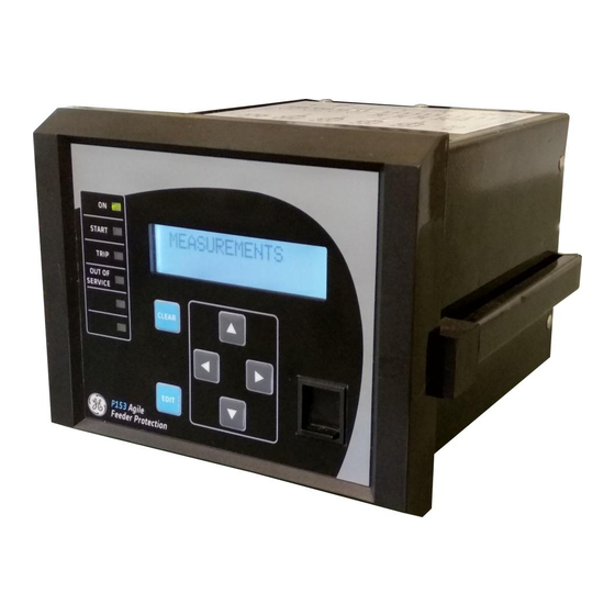
- Page 36 P50 Agile P153 4 Front Panel FRONT PANEL Figure 1: Front panel SL no Label Function Green LED indicates that the IED is in correct working order, and should be ON at all times. It turns red if the unit’s self-tests show there is an error in the hardware or software. START Amber LED flashes when the IED registers an alarm.
- Page 37 P50 Agile P153 4 Front Panel SL no Label Function Used to perform local communication with relay User Interface 2.1.1 LCD Display A backlit LCD display of 16 x 2 characters is provided for parameter and setting display, and for easy viewing of measurement, setting, fault records, date &...
- Page 38 P50 Agile P153 4 Front Panel SL no Label Function LED 1 Green LED indicates that the IED is in correct working order, and should be ON at all times. It turns red if the unit’s self-tests show there is an error in the hardware or software. LED 2 START Amber LED flashes when the IED registers an alarm.
- Page 39 P50 Agile P153 5 Configuration CONFIGURATION CHAPTER 5 P153/EN M/B...
- Page 40 P50 Agile P153 5 Configuration P153/EN M/B...
- Page 41 P50 Agile P153 5 Configuration CHAPTER OVERVIEW This chapter consists of the following sections: Chapter Overview Configuration Changing the Settings Password Entry Menus 2.3.1 Default Display 2.3.2 Main Menu Contents 2.3.3 System Data Menu 2.3.3.1 View / Edit Settings 2.3.4 View Records Menu 2.3.4.1 View Records Menu Contents...
- Page 42 P50 Agile P153 5 Configuration 2.3.17 Group 2 Menu Edit Settings 2.3.17.1 Configuration Flowcharts 2.4.1 Main Menu 2.4.2 View and Edit Settings 2.4.3 View System Data Menu Settings 2.4.4 View Records Menu 2.4.4.1 View Content 2.4.4.2 View Fault Records 2.4.4.3 View Event Records 2.4.4.4 View Maintenance Records...
- Page 43 P50 Agile P153 5 Configuration 2.4.22.3 View/Edit Settings (If setting is enabled for IEEE curve) 2.4.22.4 View/Edit Settings (If setting is enabled for DT) 2.4.23 Group 1- Thermal Overload Submenu 2.4.23.1 View/Edit Settings (If Characteristics is disabled) 2.4.23.2 View/Edit Settings (If Characteristics is set as Single) 2.4.24 Group 1- Cold Load Pickup Submenu 2.4.24.1...
- Page 44 P50 Agile P153 5 Configuration CONFIGURATION Each product has different configuration parameters according to the functions it has been designed to perform. There is, however, a common methodology used across the entire product to set these parameters. This chapter describes an overview of this common methodology, as well as providing concise instructions of how to configure the device.
- Page 45 P50 Agile P153 5 Configuration Changing the Settings Step 1: Press the (4) key to move to the next option. SYSTEM DATA Step 2: Press the (6) key to move to the next option till the relay Language displays CB Open/Close setting English : : : : : :...
- Page 46 P50 Agile P153 5 Configuration Note: The user can DISCARD SETTINGS by using the CLEAR Key. Step 10: When the ‘CLEAR’ key is pressed it will discard the changes 3 For Save and the relay will move to the next option. CLEAR For Cancel This window will flash for a moment and the control will return to the DISCARD Settings...
- Page 47 P50 Agile P153 5 Configuration SYSTEM DATA 2.3.2 Main Menu Contents Password protected window for “SYSTEM DATA’’ setting i.e. Language, SYSTEM DATA Description, Model Number, Serial Number, Software Version, Frequency, USB Address, USB Parity, USB Baud Rate, Password, Active Group, Opto I/P Status, Relay O/P Status. CB Open/Close, Opto I/P and Config Port.
- Page 48 P50 Agile P153 5 Configuration Password protected window for “COMMUNICATION’’ settings i.e. RP1 COMMUNICATION Address, RP1 Baud Rate, RP1 Parity and RP1 Timesync. Password protected window for “IO CONFIGURATION’’ settings i.e. IO CONFIGURATION Relay, LED G, LED R, AND Logic and Opto I/P. Password protected window for “O/P RELAY CONFIGURATION’’...
- Page 49 P50 Agile P153 5 Configuration Read-only Description This window shows Description of the relay. P50 Agile P153 Read-only Model Number This window shows the Model Number of the relay. P153111A1A0010A Read-only Serial Number This window shows the Serial Number of the relay. xxxP153xxxx Read-only Software Version...
- Page 50 P50 Agile P153 5 Configuration Read-only Opto I/P 4321 This window shows the Opto Input status. Status 0000 Read-only Relay O/P 4321 This window shows the Relay Output status. Status 0000 Editable setting CB Open / Close This window allows selection of the desired CB operation i.e. Open, Close and No operation.
- Page 51 P50 Agile P153 5 Configuration This window is to view the Alarm Record Alarm Record 2.3.4.2 View Fault Records This menu is to view Fault Record, Event Record, Maint Record and VIEW RECORDS Alarm record. This window shows the Fault Record Fault Record This window shows the Fault Number of latest fault.
- Page 52 P50 Agile P153 5 Configuration This window will show secondary fault current values. ic = 0.00 A in1= 0.00 A This window will show secondary fault current values. in2 = 0.00 A i2 = 0.00 A This window will show secondary fault current values. i1 = 0.00 A I2/I1 =0.00 This window will show Thermal State.
- Page 53 P50 Agile P153 5 Configuration This window shows the Event Record Event Record This window shows the Event number of latest event. Event Num = 1 By using the (5) or (6) key, the relay will scroll between Event numbers 1 to 512. This window will show date &...
- Page 54 P50 Agile P153 5 Configuration This window shows the contents of the Maintenance Record 1. Errorcode : 0004 RTC Error This window shows the date and time of error. 07/02/2018 17:20:30.596 2.3.4.5 View Alarm Records This menu is to view Fault Record, Event Record, Maint Record and VIEW RECORDS Alarm record.
- Page 55 P50 Agile P153 5 Configuration 2.3.5 Measurement Menu 2.3.5.1 View Contents This menu displays the measurements values of various parameters (i.e. MEASUREMENTS Phase current, measured and derived earth current, negative, positive phase sequence current and I2/I1 ratio as per per phase / earth CT ratio, TC (Trip Counter), BOC (Breaker Operation Counter), BOT (Breaker Operating Time) and Th State (Thermal State).
- Page 56 P50 Agile P153 5 Configuration This window shows Breaker operating time and actual Thermal State. BOT : 0 msec Th. State : 0% P153/EN M/B 5-18...
- Page 57 P50 Agile P153 5 Configuration 2.3.6 CB Control Menu 2.3.6.1 View/Edit Settings (if all settings are disabled) Password protected window for “CB CONTROL” settings: TCS Alarm, CB CONTROL TCS Timer, CB Open S’vision , CB Open Time, CB Open Alarm , CB Open Oper, CB Control By, Close Pulse Time and Open Pulse Time.
- Page 58 P50 Agile P153 5 Configuration 2.3.6.2 View/Edit Settings (if all settings are enabled) Password protected window for “CB CONTROL” settings: TCS Alarm, CB CONTROL TCS Alarm, TCS Timer, CB Open S’vision (Enabled/Disabled), CB Open Time, CB Open Alarm (Enabled/Disabled), CB Open Oper, CB Control By, Close Plus Time and Open Pulse Time.
- Page 59 P50 Agile P153 5 Configuration Editable setting Close Pulse Time By using the (5) or (6) key, the desired Close Pulse Time can be set. The setting range is from 0.1s to 50s in steps of 0.01s 0.50S Editable setting Open Pulse Time By using the (5) or (6) key, the desired Open Pulse Time can be set.
- Page 60 P50 Agile P153 5 Configuration Editable setting SET Minutes By using the (5) or (6) key, SET Minutes can be set. The setting range is from 0 to 59 in steps of 1. Editable setting SET Seconds By using the (5) or (6) key, SET Seconds can be set. The setting range is from 0 to 59 in steps of 1.
- Page 61 P50 Agile P153 5 Configuration Editable setting DST Enable By using the (5) or (6) key, DST Enable can be set as Enabled/Disabled. Enabled Editable setting DST Offset By using the (5) or (6) key, DST Offset can be set as 30Mins / 60Mins.
- Page 62 P50 Agile P153 5 Configuration Editable setting DST End Mins By using the (5) or (6) key, DST End minutes can be set. The setting range is from 0 to 1425 mins in steps of 15 mins. 60 Mins Editable setting RP Time Zone By using the (5) or (6) key, RP Time Zone can be set as Local / UTC Local...
- Page 63 P50 Agile P153 5 Configuration 2.3.8 Configuration Menu 2.3.8.1 View/Edit Settings Password protected window for “CONFIGURATION’’ settings i.e. CONFIGURATION Restore Defaults, Active Settings, Copy From, Copy To, Setting Group 1 (Enabled/Disabled), Setting Group 2 (Enabled/Disabled), System Config (Enabled/Disabled), Overcurrent (Enabled/Disabled), Neg Sequence O/C (Enabled/Disabled), Broken Conductor (Enabled/Disabled), Earth Fault 1 (Enabled/Disabled), Earth Fault 2 (Enabled/Disabled), Thermal Overload (Enabled/Disabled), Cold Load Pickup (Enabled/Disabled),...
- Page 64 P50 Agile P153 5 Configuration Editable setting Overcurrent By using the (5) or (6) key, Over Current can be Enabled or Disabled. Enabled Editable setting Neg Sequence O/C By using the (5) or (6) key, Negative Sequence O/C can be Enabled or Disabled.
- Page 65 P50 Agile P153 5 Configuration Editable setting CB Fail By using the (5) or (6) key, CB Fail can be Enabled or Disabled. Disabled Editable setting Setting Values By using the (5) or (6) key, Setting Values can be set as Primary / Secondary.
- Page 66 P50 Agile P153 5 Configuration Editable setting Clear Events By using the (5) or (6) key, Clear Event Records can be set as Yes / (set ‘Yes’ to clear event data stored in memory) Editable setting Clear Faults By using the (5) or (6) key, Clear Fault Records can be set as Yes / (set ‘Yes’...
- Page 67 P50 Agile P153 5 Configuration 2.3.12 I/O Configuration Menu 2.3.12.1 View/Edit Settings Password protected window for “OP CONTACT CONFIGURATION’’ IO CONFIGURATION settings: Relay, LED Green, LED Red, AND Logic and Opto I/P. Editable setting Relay : 4321 By using the (5) or (6) key, the output relay RL1 – RL4 can be set for desired function.
- Page 68 P50 Agile P153 5 Configuration 2.3.12.2.2 LED Green Configuration LED G (Green) can be assigned by selecting any function available in the submenus. There are in all 2 numbers of programmable LEDs identified as L5 to L6. 2.3.12.2.3 LED Red Configuration LED R (Red) can be assigned by selecting any function available in the submenus.
- Page 69 P50 Agile P153 5 Configuration Editable setting LED G HR/SR By using the (5) or (6) key, the desired LED GREEN HR/SR can be set. i.e. ‘1’=HR / ’0’=SR. Editable setting LED R HR/SR By using the (5) or (6) key, the desired LED RED HR/SR can be set. i.e.
- Page 70 P50 Agile P153 5 Configuration 2.3.14 Disturbance Record Menu 2.3.14.1 View/Edit Settings Password protected window for “Disturbance Record” settings: DISTURBANCE REC Trigger Position Editable setting Trigger Position By using the (+ /5) or (- /6) key, the desired Trigger Position can be set.
- Page 71 P50 Agile P153 5 Configuration Editable setting Test LEDs By using the (5) or (6) key, Test LEDs can be set for No Operation / Apply Test. No Operation 2.3.16 Group 1 Menu 2.3.16.1 Edit Settings Password protected window for “GROUP 1’’ settings: GROUP 1 SYSTEM CONFIG, OVERCURRENT, NEG SEQUENCE O/C, BROKEN CONDUCTOR, EARTH FAULT 1, EARTH FAULT 2, THERMAL...
- Page 72 P50 Agile P153 5 Configuration Password protected window for Cold Load Pickup i.e. tcold Time Delay, COLD LOAD PICKUP tclp Time Delay, I>1 Status, I>2 Status, I>3 Status, IN1>1 Status, IN1>2 Status, IN1>3 Status, IN2>1 Status, IN2>2 Status and IN2>3 Status. Note: Setting will be seen only when it is enabled in Configuration setting.
- Page 73 P50 Agile P153 5 Configuration Editable setting 2nd Harm Thresh By using the (5) or (6) key, the desired 2ndHarm Thresh can be set. The setting range is 5% to 70% in steps of 1%. Editable setting I>lift 2H By using the (5) or (6) key, the desired I>lift 2H setting can be done. The setting range is 4.00 to 32.00 In in steps of 0.01 In.
- Page 74 P50 Agile P153 5 Configuration Editable Setting I>1 Function By using the (5) or (6) key, I>1Function is set as IEC S Inverse. IEC S Inverse Editable setting I>1 Current Set By using the (5) or (6) key, I>1 Current Setting can be set. The setting range is from 0.05 to 4.00 In in steps of 0.01 In.
- Page 75 P50 Agile P153 5 Configuration Editable setting I>1 Current Set By using the (5) or (6) key, I>1 Current Setting can be set. The setting range is from 0.05 to 4 In in steps of 0.01 In. 1.00 A Editable setting I>1 Time Dial By using the (5) or (6) key, I>1 Time Dial can be set.
- Page 76 P50 Agile P153 5 Configuration Editable setting I>1 Time Delay By using the (5) or (6) key, I>1 Time Delay can be set. The setting range is from 0 to 100s in steps of 0.01s. 01.00 S Read-only I>1 Reset Char I>1 Reset Char is fixed as DT (Definite Time).
- Page 77 P50 Agile P153 5 Configuration Editable setting I2>3Function By using the (5) or (6) key, I2>3 Function is Disabled. Disabled Edit Settings 2.3.16.4.2 (if I2>1 Function is selected for IEC curve) Password protected window for “GROUP 1’’ setting: GROUP 1 SYSTEM CONFIG, OVERCURRENT, NEG SEQUENCE O/C, BROKEN CONDUCTOR, EARTH FAULT 1, EARTH FAULT 2, THERMAL OVERLOAD, COLD LOAD PICKUP, UNDERCURRENT and CB FAIL.
- Page 78 P50 Agile P153 5 Configuration Edit Settings 2.3.16.4.3 (if I2>1 Function is selected for IEEE / US curve) Password protected window for “GROUP 1’’ settings: GROUP 1 SYSTEM CONFIG, OVERCURRENT, NEG SEQUENCE O/C, BROKEN CONDUCTOR, EARTH FAULT 1, EARTH FAULT 2, THERMAL OVERLOAD, COLD LOAD PICKUP, UNDERCURRENT and CB FAIL.
- Page 79 P50 Agile P153 5 Configuration Edit Settings 2.3.16.4.4 (if I2>1 Function is selected for DT) Password protected window for “GROUP 1’’ settings: GROUP 1 SYSTEM CONFIG, OVERCURRENT, NEG SEQUENCE O/C, BROKEN CONDUCTOR, EARTH FAULT 1, EARTH FAULT 2, THERMAL OVERLOAD, COLD LOAD PICKUP, UNDERCURRENT and CB FAIL. Note: Group 1 Setting will be seen only when it is enabled in Configuration setting.
- Page 80 P50 Agile P153 5 Configuration 2.3.16.5 Group1 –Broken Conductor Submenu Edit Settings 2.3.16.5.1 (if function is disabled) Password protected window for “GROUP 1’’ settings: GROUP 1 SYSTEM CONFIG, OVERCURRENT, NEG SEQUENCE O/C, BROKEN CONDUCTOR, EARTH FAULT 1, EARTH FAULT 2, THERMAL OVERLOAD, COLD LOAD PICKUP, UNDERCURRENT and CB FAIL.
- Page 81 P50 Agile P153 5 Configuration Editable setting I2/I1 Time Dly-1 By using the (5) or (6) key, I2/I1 Time Dly-1 can be set. The setting range is from 0 to 100s in steps of 0.01s. 10.00S Editable setting BC Trip By using the (5) or (6) key, BC Trip is Enabled.
- Page 82 P50 Agile P153 5 Configuration Editable setting IN1>3Function By using the (5) or (6) key, IN1>3 Function is Disabled. Disabled Edit Settings 2.3.16.6.2 (if IN1>1 Function is selected for IEC curve) Password protected window for “GROUP 1’’ settings: GROUP 1 SYSTEM CONFIG, OVERCURRENT, NEG SEQUENCE O/C, BROKEN CONDUCTOR, EARTH FAULT 1, EARTH FAULT 2, THERMAL OVERLOAD, COLD LOAD PICKUP, UNDERCURRENT and CB FAIL.
- Page 83 P50 Agile P153 5 Configuration Editable setting IN1>1 2HBlocking By using the (5) or (6) key, IN1>1 2HBlocking function can be Enabled / Disabled. Disabled Edit Settings 2.3.16.6.3 (if IN1>1 Function is selected for IEEE / US curve) Password protected window for “GROUP 1’’ settings: GROUP 1 SYSTEM CONFIG, OVERCURRENT, NEG SEQUENCE O/C, BROKEN CONDUCTOR, EARTH FAULT 1, EARTH FAULT 2, THERMAL...
- Page 84 P50 Agile P153 5 Configuration range is from 0.025 to 1.200 in steps of 0.005 1.000 Note: Above setting is available if IN1>1 Reset Char is set as IDMT Editable setting IN1>1 2HBlocking By using the (5) or (6) key, IN1>1 2HBlocking function can be Enabled / Disabled.
- Page 85 P50 Agile P153 5 Configuration Editable setting IN1>1 2HBlocking By using the (5) or (6) key, IN1>1 2HBlocking function can be Enabled / Disabled. Disabled Note: The settings of IN1>2 Function and IN1>3 Function to be set in similar manner as that of IN1>1 Function.
- Page 86 P50 Agile P153 5 Configuration Edit Settings 2.3.16.7.2 (if IN2>1 Function is selected for IEC curve) Password protected window for “GROUP 1’’ settings: GROUP 1 SYSTEM CONFIG, OVERCURRENT, NEG SEQUENCE O/C, BROKEN CONDUCTOR, EARTH FAULT 1, EARTH FAULT 2, THERMAL OVERLOAD, COLD LOAD PICKUP, UNDERCURRENT and CB FAIL.
- Page 87 P50 Agile P153 5 Configuration Edit Settings 2.3.16.7.3 (if IN2>1 Function is selected for IEEE / US curve) Password protected window for “GROUP 1’’ settings: GROUP 1 SYSTEM CONFIG, OVERCURRENT, NEG SEQUENCE O/C, BROKEN CONDUCTOR, EARTH FAULT 1, EARTH FAULT 2, THERMAL OVERLOAD, COLD LOAD PICKUP, UNDERCURRENT and CB FAIL.
- Page 88 P50 Agile P153 5 Configuration Editable setting IN2>1 2HBlocking By using the (5) or (6) key, IN2>1 2HBlocking function can be Enabled / Disabled. Disabled Edit Settings 2.3.16.7.4 (if IN2>1 Function is selected for DT) Password protected window for “GROUP 1’’ settings: GROUP 1 SYSTEM CONFIG, OVERCURRENT, NEG SEQUENCE O/C, BROKEN CONDUCTOR, EARTH FAULT 1, EARTH FAULT 2, THERMAL...
- Page 89 P50 Agile P153 5 Configuration Editable setting IN2>1 2H Blocking By using the (5) or (6) key, IN2>1 2H Blocking function can be Enabled / Disabled. Disabled Note: The settings of IN2>2 Function and IN2>3 Function to be done in similar manner as that of IN2>1 Function.
- Page 90 P50 Agile P153 5 Configuration Editable setting Thermal Alarm By using the (5) or (6) key, Thermal Alarm can be set. The setting range is from 50% to 100% in steps of 1%. Editable setting Time Constant 1 By using the (5) or (6) key, Time Constant 1 can be set. The setting range is from 1 to 200 in steps of 1.
- Page 91 P50 Agile P153 5 Configuration Editable setting I>3 Status By using the 5) or (6) key, I>3 Status can be Enabled / Blocked. Enabled Editable setting IN1>1 Status By using the (5) or (6) key, IN1>1 Status can be Enabled / Blocked. Enabled Editable setting IN1>2 Status...
- Page 92 P50 Agile P153 5 Configuration Edit Settings 2.3.16.9.2 (If I>1 Function selected for IEC curve) Password protected window for “GROUP 1’’ settings: GROUP 1 SYSTEM CONFIG, OVERCURRENT, NEG SEQUENCE O/C, BROKEN CONDUCTOR, EARTH FAULT 1, EARTH FAULT 2, THERMAL OVERLOAD, COLD LOAD PICKUP, UNDERCURRENT and CB FAIL. Note: Group 1 Setting will be seen only when it is enabled and set as Active Group in Configuration setting.
- Page 93 P50 Agile P153 5 Configuration Edit Settings 2.3.16.9.3 (If I>1 Function selected for IEEE / US curve) Password protected window for “GROUP 1’’ settings: GROUP 1 SYSTEM CONFIG, OVERCURRENT, NEG SEQUENCE O/C, BROKEN CONDUCTOR, EARTH FAULT 1, EARTH FAULT 2, THERMAL OVERLOAD, COLD LOAD PICKUP, UNDERCURRENT and CB FAIL.
- Page 94 P50 Agile P153 5 Configuration Password protected window for Cold Load Pickup i.e. tcold Time Delay, COLD LOAD PKP tclp Time Delay, I>1 Status, I>2 Status, I>3 Status, IN1>1 Status, IN1>2 Status, IN1>3 Status, IN2>1 Status, IN2>2 Status and IN2>3 Status. Editable setting tcold Time Delay By using the (5) or (6) key, tcold Time Delay can be set.
- Page 95 P50 Agile P153 5 Configuration Editable setting I< Status By using the (5) or (6) key, I< Status can be Enabled / Disabled. Disabled Edit Settings 2.3.16.10.2 (If I< Status is enabled) Password protected window for “GROUP 1’’ settings: GROUP 1 SYSTEM CONFIG, OVERCURRENT, NEG SEQUENCE O/C, BROKEN CONDUCTOR, EARTH FAULT 1, EARTH FAULT 2, THERMAL OVERLOAD, COLD LOAD PICKUP, UNDERCURRENT and CB FAIL.
- Page 96 P50 Agile P153 5 Configuration By using the (5) or (6) key, I< can be set. The setting range is from I< 0.05 to 3.2 In in steps of 0.01 In 1.00 A By using the (5) or (6) key, IN< can be set. The setting range is from IN<...
- Page 97 P50 Agile P153 5 Configuration By using the (5) or (6) key, I< can be set. The setting range is from I< 0.05 to 3.2 In in steps of 0.01In 1.00 A By using the (5) or (6) key, IN< can be set. The setting range is from IN<...
- Page 98 P50 Agile P153 5 Configuration Password protected window for Earth Fault 1 i.e. IN1>1 Function, IN1>2 EARTH FAULT 1 Function and IN1>3 Function. The functions can be set as Disabled / DT / IDMT. Password protected window for Earth Fault 2 i.e. IN2>1 Function, IN2>2 EARTH FAULT 2 Function and IN2>3 Function.
- Page 99 P50 Agile P153 5 Configuration Configuration Flowcharts 2.4.1 Main Menu After the Power ON or when the relay is reset the following windows will be displayed, and the user can scroll through the main menu as below. P50 Agile P153 = V1.00 Feeder Protect’n SYSTEM DATA...
- Page 100 P50 Agile P153 5 Configuration 2.4.2 View and Edit Settings SYSTEM DATA Press the Right arrow key (4) to enter the setting menu. Language English By using the Up arrow key (5) or the Down arrow key (6) select the desired setting. Frequency This window shows the set system Frequency.
- Page 101 P50 Agile P153 5 Configuration 2.4.3 View System Data Menu Settings SYSTEM DATA Language English Description USB Address Opto I/P 4321 P50 Agile P153 Status 0000 USB Parity Model Number Relay O/P 4321 P153111A1A0010A None Status 0000 USB Baud Rate CB Open/Close Serial Number xxxP153xxxx...
- Page 102 P50 Agile P153 5 Configuration 2.4.4 View Records Menu 2.4.4.1 View Content VIEW RECORDS Fault Record Event Record Maint Record Alarm Record P153/EN M/B 5-64...
- Page 103 P50 Agile P153 5 Configuration 2.4.4.2 View Fault Records Fault Record Fault Record VIEW RECORDS Fault Num = 1 I>1 I< IN1>1 IN2>1 I2>1 Fault Num = 2 I>2 IN1>2 IN2>2 I2>2 Fault Num = 3 I>3 = 0.00 A IN1>3 IN2>3 I2>3...
- Page 104 P50 Agile P153 5 Configuration 2.4.4.3 View Event Records VIEW RECORDS Fault Record Dt: 21/02/2014 Event Record Event Num = 1 Tm: 16:15:30:225 Event Num = 2 Event No = 1 Power on 2.4.4.4 View Maintenance Records VIEW RECORDS Fault Record Event Record Main’t Rec Num = Errorcode : 0004...
- Page 105 P50 Agile P153 5 Configuration 2.4.4.5 View Alarm Records VIEW RECORDS Fault Record Event Record Maint Record TCS Alarm 24/09/2014 Alarm Record 11:24:00:842 P153/EN M/B 5-67...
- Page 106 P50 Agile P153 5 Configuration 2.4.5 Measurement Menu 2.4.5.1 View Measurements MEASUREMENTS IA = 0 A IB = 0 A = 0 A IN1 = 0 A IN2 = 0 A ia = 0.00 A : 269 ib = 0.00 A : 257 = 0.00 A BOT : 0 mSec...
- Page 107 P50 Agile P153 5 Configuration 2.4.6 CB Control Menu 2.4.6.1 View/Edit Settings (if all settings are disabled) CB CONTROL TCS Alarm CB Open S’vision Disabled CB Open Alarm Disabled CB Control by Disabled For Save EDIT SAVE Settings CLEAR For Cancel CLEAR DISCARD Settings Note: (*) indicates Edit key used to modify settings.
- Page 108 P50 Agile P153 5 Configuration 2.4.6.2 View/Edit Settings (if all settings are enabled) CB CONTROL TCS Alarm TCS Timer 0.50S CB Control by CB Open S’vision Local+Remote Enabled Close Pulse Time CB Open Time 0.50S 0.30S Open Pulse Time CB Open Alarm 0.50S Enabled CB Open Oper...
- Page 109 P50 Agile P153 5 Configuration 2.4.7 Date and Time Menu 2.4.7.1 View/Edit Settings (if all settings are disabled) DATE AND TIME Tm: 17:21:50 Dt : 12/11/14 Wed Local Time Enable Disabled DST Enable SET Seconds Disabled RP Time Zone SET Date Local SET Hours SET Month...
- Page 110 P50 Agile P153 5 Configuration 2.4.7.2 View/Edit Settings (if all settings are enabled) DATE AND TIME Tm: 17:21:50 Dt : 12/11/14 Wed Local Time Enable Fixed SET Hours Local Time Offset DST Start Mins 0 Mins 60 Mins DST End DST Enable SET Minutes Enabled...
- Page 111 P50 Agile P153 5 Configuration 2.4.8 Configuration menu 2.4.8.1 View/Edit Settings CONFIGURATION Restore Defaults No Operation Cold Load Pickup Active Settings Overcurrent Disabled Group 1 Enabled Measure’t setup Copy From Neg Sequence O/C Group 1 Disabled UnderCurr Prot Copy To Broken Conductor Disabled No Operation...
- Page 112 P50 Agile P153 5 Configuration 2.4.9 Transformer Ratios Menu 2.4.9.1 View/Edit Settings TRANS. RATIOS Phase CT Primary 100 A Phase CT Sec’y E/F CT Primary 100 A E/F CT Secondary For Save EDIT SAVE Settings CLEAR For Cancel CLEAR DISCARD Settings Note: (*) indicates Edit key used to modify settings.
- Page 113 P50 Agile P153 5 Configuration 2.4.10 Record Control Menu 2.4.10.1 View/Edit Settings RECORD CONTROL Clear Events Clear Faults Clear Dist Recs Clear Maint Thermal Reset For Save EDIT SAVE Settings CLEAR For Cancel CLEAR DISCARD Settings Note: (*) indicates Edit key used to modify settings. Refer to the View and Edit settings section. P153/EN M/B 5-75...
- Page 114 P50 Agile P153 5 Configuration 2.4.11 Communication Menu 2.4.12 View/Edit settings COMMUNICATION RP1 Address RP1 Baud Rate 57600 RP1 Parity Even RP1 Timesync Disabled For Save EDIT SAVE Settings CLEAR For Cancel CLEAR DISCARD Settings Note: (*) indicates Edit key used to modify settings. Refer to the View and Edit settings section. P153/EN M/B 5-76...
- Page 115 P50 Agile P153 5 Configuration 2.4.13 I/O Configuration Menu 2.4.14 View/Edit Settings IO CONFIGURATION Relay : 4321 Gen Strt 0000 LED G : 65 Gen Strt LED R : 65 Gen Strt AND Logic : DCBA Gen Strt 0000 Opto I/P : 4321 Rem.
- Page 116 P50 Agile P153 5 Configuration 2.4.14.1.1 I/O Configuration Submenu Setting (Output relays, LEDs and AND logic settings) IO CONFIGURATION Relay : 4321 Gen Strt 0000 Relay : 4321 Relay : 4321 Relay : 4321 Strt L1 0000 Strt I2>2 0000 Strt IN2>3 0000 Relay : 4321...
- Page 117 P50 Agile P153 5 Configuration Relay : 4321 Relay : 4321 Relay : 4321 IN1> BCBF 0000 Trip L3 0000 Trip IN1>2 0000 Relay : 4321 Relay : 4321 Relay : 4321 BC Alm 0000 Trip I>1 0000 Trip IN1>3 0000 Relay : 4321...
- Page 118 P50 Agile P153 5 Configuration Relay : 4321 Relay : 4321 Relay : 4321 Trip I< 0000 AndLogicA 0000 CBOpn Sup 0000 Relay : 4321 Relay : 4321 CBF Trip 0000 AndLogicB 0000 Relay : 4321 Relay : 4321 CBOprAlm 0000 AndLogicC 0000...
- Page 119 P50 Agile P153 5 Configuration 2.4.14.1.2 I/O Configuration Submenu Setting (Opto I/ps) IO CONFIGURATION Opto I/P : 4321 Rem. Rst. 0000 Opto I/P : 4321 Opto I/P : 4321 Opto I/P : 4321 CBF Init 0000 Blk I>2 0000 Blk IN1>3 0000 Opto I/P : 4321...
- Page 120 P50 Agile P153 5 Configuration 2.4.15 O/P Relay Configuration Menu 2.4.15.1 View/Edit Settings O/P RELAY CONFIG Contact HR/SR 0000 O/P–1 Open Time 0.50 S O/P–2 Open Time ANDEQ C Op Time ANDEQ A Op Time 0.50 S O/P–3 Open Time ANDEQ A Rst Time ANDEQ C Rst Time 0.50 S...
- Page 121 P50 Agile P153 5 Configuration 2.4.16 Disturbance Record Menu 2.4.16.1 View/Edit Settings Trigger Position DISTURBANCE REC 50 % For Save EDIT SAVE Settings CLEAR For Cancel CLEAR DISCARD Settings Note: (*) indicates Edit key used to modify settings. Refer to the View and Edit settings section. P153/EN M/B 5-83...
- Page 122 P50 Agile P153 5 Configuration 2.4.17 Commissioning Test Menu 2.4.17.1 View/Edit Settings COMMISSION TEST Test Mode Disabled Test Pattern 0000 Contact Test No Operation Test LEDs No Operation For Save EDIT SAVE Settings CLEAR For Cancel CLEAR DISCARD Settings Note: (*) indicates Edit key used to modify settings. Refer to the View and Edit settings section. P153/EN M/B 5-84...
- Page 123 P50 Agile P153 5 Configuration 2.4.18 Group1 Menu 2.4.18.1 View/Edit Settings GROUP 1 SYSTEM CONFIG OVERCURRENT THERMAL OVERLOAD NEG SEQUENCE O/C BROKEN CONDUCTOR COLD LOAD PICKUP UNDER CURRENT EARTH FAULT 1 EARTH FAULT 2 CB FAIL Note: Only those Protection Function which are enabled in CONFIGURATION setting are seen in GROUP 1 Setting.
- Page 124 P50 Agile P153 5 Configuration 2.4.18.2 Group1 System Configuration Submenu 2.4.18.2.1 View/Edit Settings (If the setting is disabled) SYSTEM CONFIG GROUP 1 Harmonic Disabled For Save EDIT SAVE Settings CLEAR For Cancel CLEAR DISCARD Settings 2.4.18.2.2 View/Edit Settings (If the setting is enabled) SYSTEM CONFIG GROUP 1 Harmonic...
- Page 125 P50 Agile P153 5 Configuration 2.4.18.3 Group1 Overcurrent Submenu 2.4.18.3.1 View/Edit Settings (If the setting is disabled) OVER CURRENT GROUP 1 I>1 Function Disabled I>2 Function Disabled I>3 Function Disabled For Save EDIT SAVE Settings CLEAR For Cancel CLEAR DISCARD Settings Note: (*) indicates Edit key used to modify settings.
- Page 126 P50 Agile P153 5 Configuration 2.4.18.3.2 View/Edit Settings (For all types of IEC curves) OVER CURRENT I>1 Function GROUP 1 IEC S Inverse I>1 Current Set 1.00 A I>1 TMS 1.000 I>1 Reset Char I>1 tRESET 1.00 S I>1 2H Blocking Disabled For Save EDIT...
- Page 127 P50 Agile P153 5 Configuration 2.4.18.3.3 View/Edit Settings (For all types of IEEE curves) I>1 Function OVER CURRENT GROUP 1 IEEE M Inverse I>1 Current Set 1.00 A I>1 Time Dial 1.00 I>1 Reset Char I>1 Reset Char IDMT I>1 tRESET I>1 RTMS 1.00 S 1.000...
- Page 128 P50 Agile P153 5 Configuration 2.4.18.3.4 View/Edit Settings (For DT) I>1 Function OVER CURRENT GROUP 1 I>1 Current Set 1.00 A I>1 Time Delay 1.00 S I>1 Reset Char I>1 tRESET 1.00 S I>1 2H Blocking Disabled For Save EDIT SAVE Settings CLEAR For Cancel CLEAR...
- Page 129 P50 Agile P153 5 Configuration 2.4.19 Negative Sequence Overcurrent Menu 2.4.19.1 View/Edit Settings (If setting is disabled) NEG SEQUENCE O/C GROUP 1 I2>1 Function Disabled I2>2 Function Disabled I2>3 Function Disabled For Save EDIT SAVE Settings CLEAR For Cancel CLEAR DISCARD Settings Note: (*) indicates Edit key used to modify settings.
- Page 130 P50 Agile P153 5 Configuration 2.4.19.2 View/Edit Settings (If setting is enabled for IEC curve) I2>1 Function NEG SEQUENCE O/C GROUP 1 IEC S Inverse I2>1 Current Set 1.00 A I2>1 TMS 1.000 I2>1 Reset Char I2>1 tRESET 1.00 S I2>1 2H Blocking Disabled For Save...
- Page 131 P50 Agile P153 5 Configuration 2.4.19.3 View/Edit Settings (If setting is enabled for IEEE curve) I2>1 Function NEG SEQUENCE O/C GROUP 1 IEEE M Inverse I2>1 Current Set 1.00 A I2>1 Time Dial 1.00 I2>1 Reset Char I2>1 Reset Char IDMT I2>1 tRESET I2>1 RTMS...
- Page 132 P50 Agile P153 5 Configuration 2.4.19.4 View/Edit Settings (If setting is enabled for DT) I2>1 Function NEG SEQUENCE O/C GROUP 1 I2>1 Current Set 1.00 A I2>1 Time Delay 1.00 S I2>1 Reset Char I2>1 tRESET 1.00 S I2>1 2H Blocking Disabled For Save EDIT...
- Page 133 P50 Agile P153 5 Configuration 2.4.20 Broken Conductor Menu 2.4.20.1 View/Edit Settings (If setting is disabled) BC Alarm BROKEN CONDUCTOR GROUP 1 Disabled BC Trip Disabled For Save EDIT SAVE Settings CLEAR For Cancel CLEAR DISCARD Settings Note: (*) indicates Edit key used to modify settings. Refer to the View and Edit settings section. P153/EN M/B 5-95...
- Page 134 P50 Agile P153 5 Configuration 2.4.20.2 View/Edit Settings (If setting is enabled) BROKEN CONDUCTOR GROUP 1 BC Alarm I2/I1Set-1 Enabled 0.50 I2/I1 Time Dly-1 10.00S BC Trip I2/I1Set-2 Enabled 0.50 I2/I1 Time Dly-2 10.00S For Save EDIT SAVE Settings CLEAR For Cancel CLEAR DISCARD Settings Note: (*) indicates Edit key used to modify settings.
- Page 135 P50 Agile P153 5 Configuration 2.4.21 Group 1- Earth Fault 1 Submenu 2.4.21.1 View/Edit Settings (If setting is disabled) EARTH FAULT 1 GROUP 1 Measured IN1>1Function Disabled IN1>2Function Disabled IN1>3Function Disabled For Save EDIT SAVE Settings CLEAR For Cancel CLEAR DISCARD Settings Note: (*) indicates Edit key used to modify settings.
- Page 136 P50 Agile P153 5 Configuration 2.4.21.2 View/Edit Settings (If setting is enabled for IEC curve) GROUP 1 EARTH FAULT 1 Measured IN1>1 Function IEC S Inverse IN1>1 Current Set 1.00 A IN1>1 TMS 1.000 IN1>1 Reset Char IN1>1 tRESET 1.00 S IN1>1 2H Blocking Disabled For Save...
- Page 137 P50 Agile P153 5 Configuration 2.4.21.3 View/Edit Settings (If setting is enabled for IEEE curve) Measured EARTH FAULT 1 GROUP 1 IN1>1 Function IEEE M Inverse IN1>1 Current Set 1.00 A IN1>1 Time Dial 1.00 IN1>1 Reset Char IN1>1 Reset Char IDMT IN1>1 tRESET IN1>1 RTMS...
- Page 138 P50 Agile P153 5 Configuration 2.4.21.4 View/Edit Settings (If setting is enabled for DT) Measured EARTH FAULT 1 GROUP 1 IN1>1 Function IN1>1 Current Set 1.00 A IN1>1 Time Delay 1.00 S IN1>1 Reset Char IN1>1 tRESET 1.00 S IN1>1 2H Blocking Disabled For Save EDIT...
- Page 139 P50 Agile P153 5 Configuration 2.4.22 Group 1-Earth Fault 2 Submenu 2.4.22.1 View/Edit Settings (If setting is disabled) EARTH FAULT 2 GROUP 1 Derived IN2>1Function Disabled IN2>2Function Disabled IN2>3Function Disabled For Save EDIT SAVE Settings CLEAR For Cancel CLEAR DISCARD Settings Note: (*) indicates Edit key used to modify settings.
- Page 140 P50 Agile P153 5 Configuration 2.4.22.2 View/Edit Settings (If setting is enabled for IEC curve) Derived EARTH FAULT 2 GROUP 1 IN2>1 Function IEC S Inverse IN2>1 Current Set 1.00 A IN2>1 TMS 1.000 IN2>1 Reset Char IN2>1 tRESET 1.00 S IN2>1 2H Blocking Disabled For Save...
- Page 141 P50 Agile P153 5 Configuration 2.4.22.3 View/Edit Settings (If setting is enabled for IEEE curve) Derived EARTH FAULT 2 GROUP 1 IN2>1 Function IEEE M Inverse IN2>1 Current Set 1.00 A IN2>1 Time Dial 1.00 IN2>1 Reset Char IN2>1 Reset Char IDMT IN2>1 tRESET IN2>1 RTMS...
- Page 142 P50 Agile P153 5 Configuration 2.4.22.4 View/Edit Settings (If setting is enabled for DT) Derived EARTH FAULT 2 GROUP 1 IN2>1 Function IN2>1 Current Set 1.00 A IN2>1 Time Delay 1.00 S IN2>1 Reset Char IN2>1 tRESET 1.00 S IN2>1 2H Blocking Disabled For Save EDIT...
- Page 143 P50 Agile P153 5 Configuration 2.4.23 Group 1- Thermal Overload Submenu 2.4.23.1 View/Edit Settings (If Characteristics is disabled) Characteristic THERMAL OVERLOAD GROUP 1 Disabled For Save EDIT SAVE Settings CLEAR For Cancel CLEAR DISCARD Settings Note: (*) indicates Edit key used to modify settings. Refer to the View and Edit settings section. 2.4.23.2 View/Edit Settings (If Characteristics is set as Single) Characteristic...
- Page 144 P50 Agile P153 5 Configuration 2.4.24 Group 1- Cold Load Pickup Submenu 2.4.24.1 View/Edit Settings COLD LOAD PKP GROUP 1 tcold Time Delay 7200 S IN1>2 Status tclp Time Delay Enabled 7200 S I>1 Status IN1>3 Status Enabled Enabled I>2 Status IN2>1 Status Enabled Enabled...
- Page 145 P50 Agile P153 5 Configuration 2.4.24.2 View/Edit Settings (I>1 Function) COLD LOAD PKP GROUP 1 tcold Time Delay 7200 S tclp Time Delay 7200 S I>1 Status Enabled NOTE: NOTE: NOTE: If the IEC Curve is selected If the IEEE Curve is selected If the DT Curve is selected for Over Current Protection for Over Current Protection...
- Page 146 P50 Agile P153 5 Configuration 2.4.25 Group 1- Undercurrent Submenu 2.4.25.1 View/Edit Settings (If I< Status is disabled) I< Status UNDER CURRENT GROUP 1 Disabled For Save EDIT SAVE Settings CLEAR For Cancel CLEAR DISCARD Settings 2.4.25.2 View/Edit Settings (If I< Status is enabled) I<...
- Page 147 P50 Agile P153 5 Configuration 2.4.26 Group 1- CB Fail Submenu 2.4.26.1 View/Edit Settings (If CB FAIL Status is disabled) CB FAIL GROUP 1 CB Fail Status Disabled I< 1.00 A IN< 1.00 A Remove I> Start Enabled Remove IN> Start Enabled For Save EDIT...
- Page 148 P50 Agile P153 5 Configuration 2.4.26.2 View/Edit Settings (If CB FAIL Status is enabled) CB FAIL GROUP 1 CB Fail Status Enabled CB Fail Timer I< 0.10S 1.00 A CB Reset IN< CB Open 1.00 A Remove I> Start Enabled Remove IN>...
- Page 149 P50 Agile P153 5 Configuration 2.4.27 Group 2 Menu 2.4.27.1 View/Edit Settings GROUP 2 SYSTEM CONFIG OVERCURRENT NEG SEQ O/C THERMAL OVERLOAD BROKEN CONDUCTOR COLD LOAD PICKUP UNDER CURRENT EARTH FAULT – 1 EARTH FAULT – 2 CB FAIL Note: Only those Protection Function which are enabled in CONFIGURATION setting are seen in GROUP 2 Settings.
- Page 150 P50 Agile P153 5 Configuration P153/EN M/B 5-112...
- Page 151 P50 Agile P153 6 Protection Functions PROTECTION FUNCTIONS CHAPTER 6 P153/EN M/B...
- Page 152 P50 Agile P153 6 Protection Functions P153/EN M/B...
-
Page 153: Table Of Contents
P50 Agile P153 6 Protection Functions CHAPTER OVERVIEW This chapter consists of the following sections: Chapter Overview Protection functions Overcurrent Protection Principles 2.1.1 IDMT Characteristics 2.1.2 Principle of Protection Function Implementation 2.1.3 Timer Hold Facility/Reset Characteristics Phase Overcurrent Protection 2.2.1 Phase Overcurrent Protection Implementation Negative Sequence Overcurrent Protection 2.3.1... -
Page 154: Overcurrent Protection Principles
P50 Agile P153 6 Protection Functions PROTECTION FUNCTIONS Overcurrent Protection Principles Most power system faults result in an overcurrent of some kind. It is the job of protection devices, formerly known as relays but now known as Intelligent Electronic Devices (IEDs), to protect the power system from such faults. -
Page 155: Principle Of Protection Function Implementation
P50 Agile P153 6 Protection Functions where; Operation time K: Constant (see the table) Measured current Is: Current threshold setting α: Constant (see the table) L: ANSI/IEEE constant (zero for IEC curve) T: Time multiplier setting (TMS) for IEC curves or Time dial setting (TD) for IEEE curves α... -
Page 156: Phase Overcurrent Protection
P50 Agile P153 6 Protection Functions Another possible situation where the timer hold facility may be used to reduce fault clearance times is for intermittent faults. An example of this may occur in a plastic insulated cable. In this application it is possible for the fault energy to melt and reseal the cable insulation, thereby extinguishing the fault. -
Page 157: Phase Overcurrent Protection Implementation
P50 Agile P153 6 Protection Functions • Line to Line to Earth (accounting for approximately 5% of all faults) • Line to Line to Line (accounting for approximately 2% of all faults) Although not as common as earth faults (single line to earth), phase faults are typically more severe. An example of a phase fault is where a fallen tree branch bridges two or more phases of an overhead line. -
Page 158: Negative Sequence Overcurrent Protection Implementation
P50 Agile P153 6 Protection Functions However, certain faults may arise which can remain undetected by such schemes. Negative Sequence Overcurrent elements can be used in such cases. Any unbalanced fault condition will produce a negative sequence current component. Therefore, a negative phase sequence overcurrent element can be used for both phase-to-phase and phase-to- earth faults. -
Page 159: Earth Fault Protection
P50 Agile P153 6 Protection Functions The Strt I2>(n) signal is fed into a timer to produce the Trip I2>(n) signal. The Negative Sequence overcurrent trip signal can be blocked by: • The Second Harmonic blocking function which is for all three phases. The blocking is activated by setting the I2>... -
Page 160: Earth Fault Protection Logic
P50 Agile P153 6 Protection Functions The fact that both EF1 and EF2 elements may be enabled at the same time leads to a number of application advantages. 2.4.2 Earth Fault Protection Logic The Earth Fault current is compared with a set threshold (IN1>(n) Current Set) for each stage. If it exceeds this threshold, a Start signal is triggered, provided there are no blocks. -
Page 161: Thermal Overload Protection Implementation
P50 Agile P153 6 Protection Functions Θi+1 = (Irms /k*IFLA) ² · [1 – exp (-t/Te)] + Θi · exp (-t/Te) TRIPPING CURVE FUNCTION OF THE PREFAULT LOAD (K = 1.1 & Te = 10 Mins) 10000.00 1000.00 100.00 10.00 1.00 0.10 MULTIPLES OF THERMAL THRESHOLD SETTINGS Iθ>... -
Page 162: Broken Conductor
P50 Agile P153 6 Protection Functions The thermal state measurement is made available in the MEASUREMENTS menu. The thermal state can be reset from the HMI panel by enabling the Thermal Reset setting to ‘Yes’ under RECORD CONTROL menu. Broken Conductor One type of unbalanced fault is the 'Series' or 'Open Circuit' fault. -
Page 163: Circuit Breaker Fail Implementation
P50 Agile P153 6 Protection Functions time. If the fault current has not been interrupted following a set time delay from circuit breaker trip initiation, the CBF protection will operate, whereby the upstream circuit breakers are back-tripped to ensure that the fault is isolated. CBF operation can also reset all start output contacts, ensuring that any blocks asserted on upstream protection are removed. -
Page 164: Cold Load Pickup Function
P50 Agile P153 6 Protection Functions CBF function Reset options Description CBF function will reset when both conditions are satisfied: CB Open + I< CB is open (i.e. CB(52B) status is active) • The phase currents and earth current is less than set current •... -
Page 165: Cold Load Pickup For Switch Onto Fault Condition
P50 Agile P153 6 Protection Functions 2.9.2 Cold Load Pickup for SWITCH ONTO FAULT Condition In some feeder applications, fast tripping may be required if a fault is already present on the feeder when it is energized. Such faults may be due to a fault condition not having been removed from the feeder, or due to earthing clamps having been left on following maintenance. - Page 166 P50 Agile P153 6 Protection Functions protected. For this reason there is another settable trigger I> lift 2H, which when exceeded, stops the 2nd harmonic blocking function. Each overcurrent protection element has I>(n) 2H Blocking setting with which the type of blocking is defined.
- Page 167 P50 Agile P153 7 Protection Parameter Settings PROTECTION PARAMETER SETTINGS CHAPTER 7 P153/EN M/B...
- Page 168 P50 Agile P153 7 Protection Parameter Settings P153/EN M/B...
- Page 169 P50 Agile P153 7 Protection Parameter Settings CHAPTER OVERVIEW This chapter consists of the following sections: Chapter Overview Protection Parameter Settings System Data CB CONTROL Settings DATE AND TIME Settings CONFIGURATION Settings TRANS. RATIOS Settings RECORD CONTROL Settings COMMUNICATION Settings IO CONFIGURATION Settings O/P RELAY CONFIG Settings 2.10...
- Page 170 P50 Agile P153 7 Protection Parameter Settings PROTECTION PARAMETER SETTINGS System Data Sr. No Parameter Defaults setting Setting / Ranges Not editable* Language English (*editable in relay models supporting multi-language option ) Description P50 Agile P153 Not editable Model Number P153xxxAxAxxxxA Not editable Serial Number...
- Page 171 P50 Agile P153 7 Protection Parameter Settings Sr. No Parameter Defaults setting Setting / Ranges This setting is used to enable (activate) or disable (turn off) the CB Open Supervision function CB Open Time 0.30 S 0.05s to 1.0s steps 0.01s This setting is used to define the circuit breaker opening time threshold.
- Page 172 P50 Agile P153 7 Protection Parameter Settings Sr. No Parameter Defaults setting Setting / Ranges Sunday / Monday / Tuesday / Wednesday / Thursday / DST End Day Sunday Friday/ Saturday Setting to specify the day of the week in which daylight saving time adjustment ends January / February / March / April / May / June / July / DST End Month October...
- Page 173 P50 Agile P153 7 Protection Parameter Settings Sr. No Parameter Defaults setting Setting / Ranges Copy To No Operation No Operation / Group 1 / Group 2 This command allows the displayed settings to be copied to a selected setting group. Setting Group 1 Enabled Enabled / Disabled...
- Page 174 P50 Agile P153 7 Protection Parameter Settings Sr. No Parameter Defaults setting Setting / Ranges E/F CT Primary 100A 1 to 30000A step 1A This setting determines the earth current transformer input primary current rating. E/F CT Secondary 1A or 5A This setting determines the earth current transformer input secondary current rating.
- Page 175 P50 Agile P153 7 Protection Parameter Settings Sr. No Parameter Defaults setting Setting / Ranges This cell sets the Green LED L5 – L8 for desired function. LED R 6 LED L6…..5LED L5 Gen Strt* 1 = assigned ; 0 = not assigned This cell sets the RED LED L5 –...
- Page 176 P50 Agile P153 7 Protection Parameter Settings 2.10 DISTURBANCE RECORD Settings Sr. No Parameter Defaults setting Setting / Ranges Password 0000 0000 to zzzz This setting specifies to enter the set password Trigger Position 10% to 90% step 1% This setting sets the trigger point as a percentage of the duration. For example, the default setting, which is set to 50% (of 1.0s) gives 0.5s prefault and 0.5s post fault recording times.
- Page 177 P50 Agile P153 7 Protection Parameter Settings Sr. No Parameter Default setting Setting Range If DT 0.05 to 35.00*In step 0.01*In I>1 Current Set 1.00*In If IDMT 0.05 to 4.00*In step 0.01*In This setting determines the pick-up setting for first stage overcurrent element. I>1 Time Delay 1.00 S 0s to 100s step 0.01s...
- Page 178 P50 Agile P153 7 Protection Parameter Settings Sr. No Parameter Default setting Setting Range This setting determines the enabling/disabling of blocking second stage overcurrent element due to presence of inrush current. If I>2 Blocking and 2nd Harmonic settings are enabled, then (I>2) trip command will be blocked in case 2nd harmonics content in any phase is above the 2ndHarm Thresh.
- Page 179 P50 Agile P153 7 Protection Parameter Settings Sr. No Parameter Default setting Setting Range IN1>1 TMS 1.000 0.025 to 1.2 step 0.005 This time multiplier setting is used to adjust the operating time of the IEC / UK IDMT characteristic. IN1>1 Time Dial 1.00 0.01 to 100 step 0.01...
- Page 180 P50 Agile P153 7 Protection Parameter Settings Sr. No Parameter Default setting Setting Range Disabled / DT / IEC S Inverse / S Inverse (1.3Sec) / IEC V Inverse / IEC E Inverse / UK LT Inverse / IEEE M Inverse / IEEE V Inverse IN1>3 Function IEC S Inverse / IEEE E Inverse / US Inverse / US ST...
- Page 181 P50 Agile P153 7 Protection Parameter Settings Sr. No Parameter Default setting Setting Range IN2>1 RTMS 1.000 0.025 to 1.2 step 0.005 This setting determines the reset/release time for IEEE IDMT characteristic IN2>1 tRESET 1.00 S 0s to 100s step 0.01s This setting determines the reset/release time for Definite Time (DT) and all IDMT curve IN2>1 2H Blocking Disabled...
- Page 182 P50 Agile P153 7 Protection Parameter Settings Sr. No Parameter Default setting Setting Range This setting determines the pick-up setting for third stage derived earth fault element. IN2>3 Time Delay 1.00 S 0s to 200s step 0.01s This setting determines the time-delay for the definite time setting if selected for third stage of derived earth fault element. IN2>3 TMS 1.000 0.025 to 1.2 step 0.005...
- Page 183 P50 Agile P153 7 Protection Parameter Settings Sr. No Parameter Default setting Setting Range tclp Time Delay 7200 S 0 to 14400s step 1s This setting controls the period of time for which the relevant overcurrent and earth fault settings are altered or inhibited following circuit breaker closure.
- Page 184 P50 Agile P153 7 Protection Parameter Settings Sr. No Parameter Default setting Setting Range IN1>1 Current Set 0.20*In 0.05 to 4.00 step 0.01*In This setting determines the new pick-up setting for first stage earth fault element during the tclp time delay. IN1>1 Time Delay 0.01 S 0s to 200s step 0.01s...
- Page 185 P50 Agile P153 7 Protection Parameter Settings Sr. No Parameter Default setting Setting Range This setting determines the new time multiplier setting for the first stage derived earth fault element to adjust the operating time of the IEEE / US IDMT characteristic during the tclp time. IN2>2 Status Enabled Blocked / Enabled...
- Page 186 P50 Agile P153 7 Protection Parameter Settings Sr. No Parameter Default setting Setting Range I2>1 Time Dial 1.00 0.01 to 100 step 0.01 This time multiplier setting is used to adjust the operating time of the IEEE / US IDMT curves. I2>2 Reset Char DT/IDMT This setting determines the type of reset/release characteristics.
- Page 187 P50 Agile P153 7 Protection Parameter Settings Sr. No Parameter Default setting Setting Range Disabled / DT / IEC S Inverse / S Inverse (1.3Sec) / IEC V Inverse / IEC E Inverse / UK LT Inverse / IEEE M Inverse / IEEE V Inverse I2>3 Function IEC S Inverse / IEEE E Inverse / US Inverse / US ST...
- Page 188 P50 Agile P153 7 Protection Parameter Settings Sr. No Parameter Defaults setting Setting / Ranges CB Fail Timer 0.1 S 0s to 50s step 0.01s This setting sets the time delay in which the CB opening must be detected. 1=I< Only 2=CB Open + I<...
- Page 189 P50 Agile P153 8 Monitoring & Control MONITORING & CONTROL CHAPTER 8 P153/EN M/B...
- Page 190 P50 Agile P153 8 Monitoring & Control P153/EN M/B...
- Page 191 P50 Agile P153 8 Monitoring & Control CHAPTER OVERVIEW This chapter consists of the following sections: Chapter Overview Monitoring & Control Monitoring Functions (Event, Fault, Disturbance Record) 2.1.1 Event Record 2.1.2 Alarm Record 2.1.3 Fault Record 2.1.4 Maintenance Record 2.1.5 Disturbance Record Record Control Display of Measuring Parameters...
- Page 192 P50 Agile P153 8 Monitoring & Control MONITORING & CONTROL Monitoring Functions (Event, Fault, Disturbance Record) The IED logs three different types of record. These are Event, Fault and Disturbance records, which are stored in the IEDs non-volatile memory. It is important to log records because this allows you to establish the sequence of events that occurred, for example following a particular power system condition.
- Page 193 P50 Agile P153 8 Monitoring & Control 2.1.2 Alarm Record The P153 logs any alarm conditions it generates as individual events. Details of the event are displayed in the Alarm Record submenu under VIEW RECORDS menu. A Time and Date stamp is always associated with the event in question and is displayed after the event description.
- Page 194 P50 Agile P153 8 Monitoring & Control disturbance records locally via the front panel LCD. This waveform can be downloaded via the communication port for further analysis. The fault recording is set by Trigger Position cell. The Trigger Position cell sets the trigger point as a percentage of the duration.
- Page 195 P50 Agile P153 8 Monitoring & Control Parameter Unit Description Th State Thermal state In the event of a fault, the type of the fault and fault current are displayed on LCD. The IED measures the fault current and stores it in the non-volatile memory. Opto Inputs The device supports 4 numbers of opto-inputs.
- Page 196 P50 Agile P153 8 Monitoring & Control For details regarding the operating voltage and its threshold values, please refer to the Technical Specification section of this manual. Output Relays The device supports 4 numbers of relay output. The use of these relay outputs depends on the application.
- Page 197 P50 Agile P153 8 Monitoring & Control Function Description StrtIN1>3 Start Measured E/F stage 3 StrtIN2>1 Start Derived E/F stage 1 StrtIN2>2 Start Derived E/F stage 2 StrtIN2>3 Start Derived E/F stage 3 Strt BC Start Broken Conductor Strt THOL Start Thermal Alarm Strt CLP Start Cold load Pickup...
- Page 198 P50 Agile P153 8 Monitoring & Control Function Description AndLogicD AND logic equation D CB Trip Circuit Breaker Trip CB Close Circuit Breaker Close TCS Alarm Trip circuit supervision Alarm CBOpn Sup CB Open supervision Alarm Note: The above functions can be assigned to LEDs and AND Logic Equation. 2.5.2 O/P Relay Configuration All relay contacts can be individually set as self-reset or latching.
- Page 199 P50 Agile P153 8 Monitoring & Control Figure 2: Output contact logic Programmable LEDs The device supports two programmable LEDs. All of the programmable LEDs on the unit are bi-colour and can be set to RED or GREEN. The use of these LEDs depends on the application. There are a number of settings associated with the relay outputs.
- Page 200 P50 Agile P153 8 Monitoring & Control Figure 3: LEDs configuration logic The functions that can be assigned to Green LED and Red LED are same to relay contact. All Green LEDs and Red LEDs can be individually set as self-reset or latching The selection of HR/SR type is made by changing bits value from 0 or 1 in O/P Contact Configuration setting.
- Page 201 P50 Agile P153 8 Monitoring & Control Figure 4: AND logic equation AND Logic application example The figure below is an example for AND logic implementation in the relay. There are two inputs to the AND equations, one is SF6 Gas low signal which is externally wired to Opto I/P 1 of relay and other input is TCS Alarm which is internally generated signal.
- Page 202 P50 Agile P153 8 Monitoring & Control Breaker opening time is displayed on the LCD display under MEASUREMENTS menu. The CB Open Supervision logic is explained in following diagram: Figure 6: CB open supervision logic 2.8.2 CB Open Operation Alarm Every circuit breaker operation results in some degree of wear for its components.
- Page 203 P50 Agile P153 8 Monitoring & Control The control operations of CB such as CB Open and CB Close command is controlled locally through relay HMI or Remote operation. Type of Control operation is enabled (i.e. Local, Remote or Local + Remote) in the CB CONTROL menu.
- Page 204 P50 Agile P153 8 Monitoring & Control For CB OPEN command: Once a CB Open command is received from local or remote the assigned relay contact for the CB trip will operate. Simultaneously the relay starts monitoring the status of opto input 52B. If the status of 52B input is not high after the expiry of open pulse time (settable in the range of 0.1 to 50 sec), then the relay output contact, which is assigned to CB Open fail, will operate.
- Page 205 P50 Agile P153 8 Monitoring & Control Figure 11: TCS Scheme When the breaker is closed, supervision current passes through opto input 1 and the trip coil. When the breaker is open current flows through opto input 2 and the trip coil. No supervision of the trip path is provided whilst the breaker is open.
- Page 206 P50 Agile P153 8 Monitoring & Control The output contact assigned to ‘Relay OK’ signal remains in active state when the relay is Healthy, i.e. NO contact will be in closed position and vice versa. The output contact assigned to ‘Relay OK’ will become inactive in case any error is detected / failure of auxiliary supply.
- Page 207 P50 Agile P153 9 SCADA Communications SCADA COMMUNICATIONS CHAPTER 9 P153/EN M/B...
- Page 208 P50 Agile P153 12 SCADA Communications P153/EN M/B...
- Page 209 P50 Agile P153 9 SCADA Communications CHAPTER OVERVIEW This chapter consists of the following sections: Chapter Overview SCADA Communications Modbus 2.1.1 Overview 2.1.1.1 Physical Connection and Link Layer 2.1.2 MODBUS Functions 2.1.2.1 Protocol Mapping IEC60-870-5-103 2.2.1 Overview 2.2.2 Physical Connection and Link Layer 2.2.3 Initialisation 2.2.4...
- Page 210 P50 Agile P153 12 SCADA Communications SCADA COMMUNICATIONS Modbus This section describes how the MODBUS standard is applied to the Px50 platform. It is not a description of the standard itself. The level at which this section is written assumes that the reader is already familiar with the MODBUS standard.
- Page 211 Hour, Min 16 bit 42051 Milliseconds 16 bit 42052 For GE P50 Agile relays on Modbus, time synchronization is possible via a broadcast command to 800H (4x02049 through 4x02052). The format is inverted IEC 870-5-4 CP56Time2a Words Year 00..99 0 Month...
- Page 212 P50 Agile P153 12 SCADA Communications (=0 valid , =1 non valid or non synchronised in system case) First Day of week is Monday Sr. No. Function Register No. of Format Reg. Address Code Regs Type Status and Logical Status Gen Strt 1 bit 12769...
- Page 213 P50 Agile P153 9 SCADA Communications Sr. No. Function Register Format Reg. Address Map Code Type Regs Trip IN1>3 1 bit 12808 Trip IN2>1 1 bit 12809 Trip IN2>2 1 bit 12810 Trip IN2>3 1 bit 12811 Trip BC 1 bit 12812 THOL Trip 1 bit...
- Page 214 P50 Agile P153 12 SCADA Communications 32 bit Float 33287 – 33288 Th State 32 bit Float 33289 – 33290 32 bit Float 33291 – 33292 32 bit Float 33293 – 33294 32 bit Float 33295 – 33296 I2/I1 32 bit Float 33297 –...
- Page 215 P50 Agile P153 9 SCADA Communications 2.2.2 Physical Connection and Link Layer There are two options available for connecting on IEC 60870-5-103: • Front USB port • Rear serial port 1- for permanent SCADA connection via RS485 The IED address and baud rate can be selected using the front panel menu or with P50 Agile configurator.
- Page 216 P50 Agile P153 12 SCADA Communications 2.2.8 Commands The list of commands supported P153 relay is given in table below (refer Sr.No.8). The device will respond to valid Control Command with ASDU1 and a cause of transmission indicating ‘Positive (COT-20) / Negative (COT-21) acknowledgement’. The device will respond to commands with invalid FUN/ INF combination with an ASDU 1, with a cause of transmission indicating ‘negative acknowledgement’.
- Page 217 P50 Agile P153 9 SCADA Communications Sr. No. Description Semantics of INFORMATION NUMBER: Fault indications in monitor direction Gen Strt 1,7,9 Strt L1 1,7,9 Strt L2 1,7,9 Strt L3 1,7,9 Strt I>1 1,7,9 Strt I>2 1,7,9 Strt I>3 1,7,9 Strt I2>1 1,7,9 Strt I2>2 1,7,9...
- Page 218 P50 Agile P153 12 SCADA Communications Sr. No. Description Trip IN2>3 Trip BC THOL Trip Trip I< CBF Trip Ext Trip CBOpn Sup BC Alarm Sr. No. Description Semantics of INFORMATION NUMBER: Measurands in monitor direction Measurand I 2, 7 L 1,2,3 IN1, Th State, IN2, I2, I1, I2/I1 ratio...
- Page 219 P50 Agile P153 9 SCADA Communications Close ON/OFF Output 1 ON/OFF Output 2 ON/OFF Output 3 ON/OFF Output 4 ON/OFF P153/EN M/B 9-13...
- Page 220 P50 Agile P153 12 SCADA Communications 9-14 P153/EN M/B...
- Page 221 P50 Agile P153 10 Installation INSTALLATION CHAPTER 10 P153/EN M/B 10-1...
- Page 222 P50 Agile P153 10 Installation 10-2 P153/EN M/B...
- Page 223 P50 Agile P153 10 Installation CHAPTER OVERVIEW This chapter consists of the following sections: Chapter Overview Installation Handling the Goods 2.1.1 Receipt of the Goods 2.1.2 Unpacking the Goods 2.1.3 Storing the Goods 2.1.4 Dismantling the Goods Mounting the Device 2.2.1 Flush Panel Mounting Relay Connection...
-
Page 224: Installation
P50 Agile P153 10 Installation INSTALLATION Handling the Goods Our products are of robust construction but require careful treatment before installation on site. This section discusses the requirements for receiving and unpacking the goods, as well as associated considerations regarding product care and personal safety. Caution: Before lifting or moving the equipment you should be familiar with the Safety Information chapter of this manual. -
Page 225: Mounting The Device
P50 Agile P153 10 Installation Mounting the Device The products are available for flush panel mounting only 2.2.1 Flush Panel Mounting The P153 supports flush panel mounting and can be mounted into panels using fitting clamps with M4 X 12 screws. The fitting clamp and screws are supplied along with the relay. -
Page 226: Relay Connection
P50 Agile P153 10 Installation Caution: All screws of fitting clamps to be properly tightened. Always use M4 x 12 screws for fitting the clamps. The mounted relay is shown below. Figure 3: Relay mounted on the panel-front view Figure 4: Relay mounted on the panel-rear view Relay Connection Before installation of the relay check the correct working procedure as to ensure safety. -
Page 227: Relay Operating Condition
P50 Agile P153 10 Installation Before energizing the following should be checked Voltage rating and polarity. CT circuit rating and integrity of connection. Protective fuse rating. Integrity of the earthing connection. Voltage and current rating of external wiring, applicable as per application. 2.3.1.1 Relay Operating Condition The equipment should be operated within the specified electrical and environmental limits. -
Page 228: Terminal Blocks
P50 Agile P153 10 Installation Figure 5: P153 rear view-terminal connection 2.3.3 Terminal Blocks 2.3.3.1 CT connections P153 devices use terminal blocks as shown below. The terminal block consists of up to 12 x M3.5 screw terminals for CT connections. The CT wires should be terminated with 90° L-shape ring lugs, with no more than two lugs per terminal. -
Page 229: Rear Serial Port Connection
P50 Agile P153 10 Installation 2.3.3.3 Rear Serial Port connection The rear serial port is intended for use with a permanently wired connection to a remote SCADA system. The physical connectivity is achieved using three terminals: D1, D2 terminals for signal connection, and D3 terminal for connecting cable shield. -
Page 230: Current Transformers
P50 Agile P153 10 Installation Note: To prevent any possibility of electrolytic action between brass or copper ground conductors and the rear panel of the product, precautions should be taken to isolate them from one another. This could be achieved in several ways, including placing a nickel-plated or insulating washer between the conductor and the product case, or using tinned ring terminals. -
Page 231: Eia(Rs) 485 Connections
P50 Agile P153 10 Installation Note 1: Terminal blocks must not be detached whilst any current transformer (CT) circuit is live. CT shorting must be achieved by external means; the product does not include this facility. Note 2: For 5A CT secondary, we recommend using 2 x 2.5 mm PVC insulated multi-stranded copper wire. -
Page 232: Case Dimensions
P50 Agile P153 10 Installation Case dimensions Figure 10: Case dimensions Note: All dimensions in mm. 10-12 P153/EN M/B... - Page 233 P50 Agile P153 13 Commissioning Instructions COMMISSIONING INSTRUCTIONS CHAPTER 11 P153/EN M/B 13-1...
- Page 234 P50 Agile P153 13 Commissioning Instructions 13-2 P153/EN M/B...
- Page 235 P50 Agile P153 13 Commissioning Instructions CHAPTER OVERVIEW This chapter consists of the following sections: Chapter Overview Commissioning Commissioning Test Menu 2.1.1 Test Mode 2.1.2 Test Pattern 2.1.3 Contact Test 2.1.4 Test LEDs 2.1.5 Opto Input status check 2.1.6 Opto Output status check 2.1.7 Commissioning Test equipment required 2.1.8...
-
Page 236: Commissioning
P50 Agile P153 13 Commissioning Instructions COMMISSIONING The P153 is fully numerical in its design - it has self-supervision function which continuously keeps track of its internal hardware, and it will display a message on the LCD screen if it detects the failure of any component. -
Page 237: Opto Output Status Check
P50 Agile P153 13 Commissioning Instructions 2.1.6 Opto Output status check The Opto O/P cell under SYSTEM DATA menu can be used to monitor the status of the relay outputs. The cell is a binary string that displays the status of the relay outputs where '1' means energised and '0' means de-energised. -
Page 238: Ct Polarity
P50 Agile P153 13 Commissioning Instructions • Trip Coil contact connection should be as per the given schematic diagram. • Latching type annunciation contact connection as per requirement of site. 2.1.9.1 Earthing An earthing terminal is provided at the back of the relay. Ensure that the case earthing connections are used to connect the IED to a local earth bar using an adequate conductor. - Page 239 P50 Agile P153 13 Commissioning Instructions Apply a current of twice the setting shown in the I>1 Current Set cell in the OVERCURRENT menu. Note the time displayed when the timer stops. Check that the red trip LED has illuminated. 2.1.11.4 Checking the Operating time Check that the operating time recorded by the timer is within the range shown below.
-
Page 240: Final Check
P50 Agile P153 13 Commissioning Instructions Check that the current transformer polarities are correct by measuring the negative sequence current magnitude. or derived earth fault current. Ensure the current flowing in the neutral circuit of the current transformers is negligible. Compare the values of the secondary phase currents with the measured values, which can be found in the MEASUREMENTS menu. - Page 241 P50 Agile P153 12 Maintenance and Troubleshooting MAINTENANCE AND TROUBLESHOOTING CHAPTER 12 P153/EN M/B 12-1...
- Page 242 P50 Agile P153 12 Maintenance and Troubleshooting 12-2 P153/EN M/B...
- Page 243 P50 Agile P153 12 Maintenance and Troubleshooting CHAPTER OVERVIEW This chapter consists of the following sections: Chapter Overview MAINTENANCE Maintenance checks 2.1.1 Opto-Isolators 2.1.2 Output Relays 2.1.3 Measurement Accuracy Changing the Battery 2.2.1 Replacing the Lithium Coin Battery Replacing the Unit Cleaning Troubleshooting P153/EN M/B...
- Page 244 P50 Agile P153 12 Maintenance and Troubleshooting MAINTENANCE Maintenance checks In view of the critical nature of the application, General Electric products should be checked at regular intervals to confirm they are operating correctly. The devices are self-supervising and so require less maintenance than earlier designs of protection devices.
- Page 245 P50 Agile P153 12 Maintenance and Troubleshooting The data maintained includes event, fault and disturbance records and the thermal state at the time of failure. The battery periodically needs changing if there is a low battery condition, to ensure reliability. The lithium coin battery is located on the CPU PCB.
- Page 246 P50 Agile P153 12 Maintenance and Troubleshooting Figure 2: Removal of front bazel Locate the exact position of the lithium coin battery on the CPU PCB Figure 3: Battery location on CPU PCB Gently remove the battery. If necessary, use a small insulated screwdriver. Make sure the metal terminals in the battery socket are free from corrosion, grease and dust.
- Page 247 P50 Agile P153 12 Maintenance and Troubleshooting Figure 4: Correct polarity of battery Only use Panasonic make Lithium battery type BR2032 or equivalent with a nominal voltage of 3 V. Ensure that the battery is held securely in its socket and that the battery terminals make good contact with the socket terminals.
- Page 248 P50 Agile P153 12 Maintenance and Troubleshooting Cleaning Warning: Before cleaning the IED, ensure that all AC and DC supplies and transformer connections are isolated to prevent any chance of an electric shock while cleaning. Only clean the equipment with a lint-free cloth dampened with clean water. Do not use detergents, solvents or abrasive cleaners as they may damage the product's surfaces and leave a conductive residue.
- Page 249 P50 Agile P153 12 Maintenance and Troubleshooting TROUBLESHOOTING The relay continuously monitors the hardware and detects any hardware fault/error. In case of hardware failure relay displays the corresponding error code on the LCD. • The IED performs continuous periodic self-diagnostic procedure at every one minute for checking of all errors excluding Setting Error.
- Page 250 P50 Agile P153 12 Maintenance and Troubleshooting 12-10 P153/EN M/B...
- Page 251 P50 Agile P153 13 Technical Specifications TECHNICAL SPECIFICATIONS CHAPTER 13 P153/EN M/B 13-1...
- Page 252 P50 Agile P153 13 Technical Specifications 13-2 P153/EN M/B...
- Page 253 P50 Agile P153 13 Technical Specifications CHAPTER OVERVIEW This chapter consists of the following sections: Chapter Overview Technical Specification 2.1.1 Standards Compliance P153/EN M/B 13-3...
- Page 254 P50 Agile P153 13 Technical Specifications TECHNICAL SPECIFICATION Current Input CT secondary 1 A or 5 A (by wiring) Nominal burden at rated current (without < 0.20 VA at rated current (In) tripping condition) Thermal withstand capacity 100 x rated current (In) for 1s III.
- Page 255 P50 Agile P153 13 Technical Specifications Output Contact Non Latching contact Continuous Continuous 5A/250 V AC Make & carry 30A for 3s Short time withstand capacity 50A for 1s Breaking capacity AC- 1250 VA max. 5A or 250 V (PF= 0.4) DC- 100 W resistive max.
- Page 256 P50 Agile P153 13 Technical Specifications Operating time IDMT characteristic shape As per clause 5.2 of IEC60255-151 or 50 ms whichever is greater DT operation ± 5% or 55 ms whichever is greater** ** Reference condition Currents applied at 2x pick-up level or higher Reset time Set delay ±10%...
- Page 257 P50 Agile P153 13 Technical Specifications Operating time IDMT characteristic shape As per clause 5.2 of IEC60255-151 or 50 ms whichever is greater DT operation ± 5% or 55 ms whichever is greater** ** Reference condition Currents applied at 2x pick-up level or higher CB Fail Operating time...
- Page 258 P50 Agile P153 13 Technical Specifications 1) 2kV rms for 1 minute between all terminals connected together with case earth. IEC 60255-27:2005 Dielectric voltage 2) 2kV rms for 1 minute between independent circuits with case earth. (incl. corrigendum 2007) withstand test 3) 1.5kV rms for 1 minute across open contacts of changeover output relays.
- Page 259 P50 Agile P153 13 Technical Specifications Auxiliary Supply tests IEC 61000-4-29 Class A Residual voltage D.C. voltage dips IEC60255-26(ed3.0)- 1) At 40% for 200ms. 2) At 70% for 500ms. 2013 1) DC auxiliary supply interruptions for 10, 20ms with no loss of protection. IEC 61000-4-29 Class A DC voltage IEC60255-26(ed3.0)-...
- Page 260 P50 Agile P153 13 Technical Specifications Immunity tests 1) 2.5 kV Common mode a) Between independent circuit and case earth. IEC 60255-22-1 and b) Independent circuit. High frequency IEC60255-26(ed3.0)-2013 disturbance test 2) 1 kV Differential mode a) Independent circuit. EUT condition : Energised EN61000-4-2:2009 Level 3 1) 8kV air discharge and Level 4...
- Page 261 P50 Agile P153 13 Technical Specifications Mechanical tests Frequency range 10 to 250Hz Vibration Peak acceleration 2 gn endurance EN 60255-21-1:1996 Class 2 test No. of sweep cycles per axis EUT condition Non energised Peak acceleration 10 gn Pulse duration 11 ms Shock EN 60255-21-2:1996 Class 2...
- Page 262 P50 Agile P153 13 Technical Specifications Environmental tests Start-up +20 °C (EUT energised) Functional verification tests for 2 hours Intermediate 0°C (EUT energised) Functional verification tests for 2 hours Intermediate -10°C (EUT energised) Functional verification tests for 2 hours Low temperature - 25°C (EUT Functional verification tests for 96 hours IEC 60255-1, Cold test...
- Page 263 P50 Agile P153 14 Wiring Diagrams WIRING DIAGRAMS CHAPTER 14 P153/EN M/B 14-1...
- Page 264 P50 Agile P153 14 Wiring Diagrams 14-2 P153/EN M/B...
- Page 265 P50 Agile P153 14 Wiring Diagrams CHAPTER OVERVIEW This chapter consists of the following sections: Chapter Overview Wiring diagram P153/EN M/B 14-3...
- Page 266 P50 Agile P153 14 Wiring Diagrams WIRING DIAGRAM Figure 1: P153 wiring diagram 14-4 P153/EN M/B...
- Page 268 Imagination at work Grid Solutions St Leonards Building Redhill Business Park Stafford, ST16 1WT, UK +44 (0) 1785 250 070 www.gegridsolutions.com/contact © 2019 General Electric. All rights reserved. Information contained in this document is indicative only. No representation or warranty is given or should be relied on that it is complete or correct or will apply to any particular project. This will depend on the technical and commercial circumstances.
Need help?
Do you have a question about the Agile P50 Series and is the answer not in the manual?
Questions and answers