Table of Contents
Advertisement
Advertisement
Table of Contents

Subscribe to Our Youtube Channel
Related Manuals for Axis A1601


Summary of Contents for Axis A1601
- Page 1 AXIS A1601 Network Door Controller User Manual...
-
Page 2: Table Of Contents
AXIS A1601 Network Door Controller Table of Contents Solution overview ......... . . -
Page 3: Solution Overview
AXIS A1601 Network Door Controller Solution overview Solution overview The network door controller can easily be connected to and powered by your existing IP network with no need for special cabling. - Page 4 AXIS A1601 Network Door Controller Solution overview Each network door controller is an intelligent device that is easily mounted close to a door. It can power and control up to two readers.
-
Page 5: Product Overview
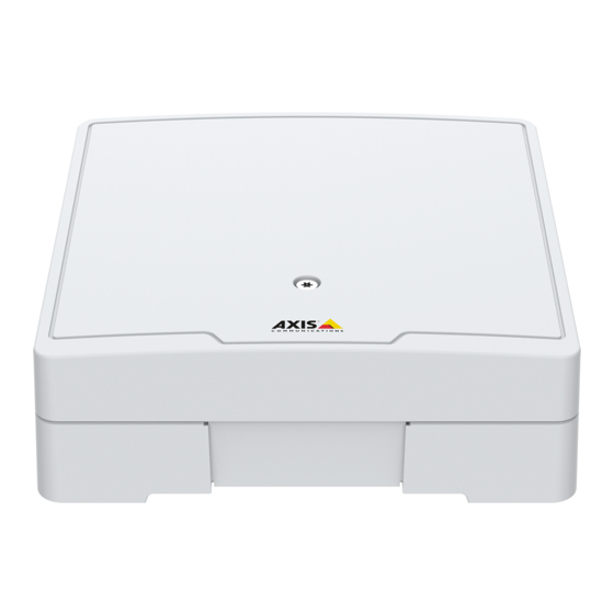
AXIS A1601 Network Door Controller Product overview Product overview Door connector on page 38 (2x) Reader connector on page 37 (2x) Control button on page 36 Reader overcurrent LED Relay overcurrent LED Auxiliary connector on page 39 Relay connector on page 39 (2x) - Page 6 AXIS A1601 Network Door Controller Product overview 15 Network connector on page 36 16 External connector on page 40 17 Reversible cable cover 18 Grounding position...
-
Page 7: Find The Device On The Network
Most routers are pre-configured to stop attempts to access the private network (LAN) from the public network (internet). If the Axis product is located on an intranet (LAN) and you want to make it available from the other (WAN) side of a NAT (Network Address Translator) router, turn on NAT traversal. -
Page 8: The Overview Page
It also enables you to identify the door controller on the network. The first time you access the Axis product, the Overview page will prompt you to configure the hardware, to set date and time, and to configure the network settings. For more information about configuring the system, see Configuration – step by step on page 9 . -
Page 9: System Configuration
To open the product’s setup pages, click Setup in the top right-hand corner of the Overview page. The Axis product can be configured by administrators. For more information about users and administrators, see page 25. Configuration – step by step Before you start using the access control system, you should complete the following setup steps: 1. -
Page 10: Configure The Network Settings
Configure the hardware You can connect readers, locks and other devices to the Axis product before you complete the hardware configuration. However, it will be easier to connect devices if you complete the hardware configuration first. This is because a hardware pin chart will be... - Page 11 How to export a hardware configuration file The hardware configuration of the Axis product can be exported to make multiple copies of the same hardware setup. You can also store exported files as backups and use them to restore previous hardware configurations.
- Page 12 How to create a new hardware configuration without peripherals 1. Go to Setup > Hardware Configuration and click Start new hardware configuration. 2. Enter a name for the Axis product. 3. Select the number of connected doors and click Next.
- Page 13 AXIS A1601 Network Door Controller System configuration • Access time – Set the number of seconds the door shall remain unlocked after access has been granted. The door remains unlocked until the door has been opened or until the set time has been reached. The door will lock when it closes regardless of whether the access time has expired or not.
- Page 14 How to create a new hardware configuration for wireless locks 1. Go to Setup > Hardware Configuration and click Start new hardware configuration. 2. Enter a name for the Axis product. 3. In the list of peripherals, select a manufacturer for a wireless gateway.
- Page 15 Important Before creating a HW configuration you need to add a user in AXIS A9188 Network I/O Relay Module. Go to the A9188 web interface > Preferences > Additional device configuration > Basic setup > Users > Add > User setup.
-
Page 16: Verify The Hardware Connections
Important • Before you set up the network periphals you need to add a user in AXIS A9188 Network I/O Relay Module. Go to the AXIS A9188 web interface > Preferences > Additional device configuration > Basic setup > Users > Add > User setup. -
Page 17: Configure Cards And Formats
AXIS A1601 Network Door Controller System configuration • Reader: Feedback – Verify the reader feedback, for example sounds and LED signals, for different commands. Select the command and click Test. Which types of feedback that are available depends on the reader. For more information, see Reader feedback on page 23. - Page 18 AXIS A1601 Network Door Controller System configuration To delete a field map in the Edit card format or Add card format dialog, click To delete a card format, click Important • You can only enable and disable card formats if the door controller has been configured with at least one reader. See Configure the hardware on page 10 and How to configure readers and REX devices on page 13.
-
Page 19: Configure Services
AXIS A1601 Network Door Controller System configuration BinLE2Hex – Binary data is encoded as hex-lowercase numbers in little endian bit order. The hexadecimal system, also known as the base-16 number system, consists of 16 unique symbols: the numbers 0–9 and the letters a–f. -
Page 20: Maintenance Instructions
8. An overview of the doors included in the configuration is shown. Click Settings to configure each door individually. Maintenance Instructions To keep the access control system running smoothly, Axis recommends regular maintenance of the access control system, including door controllers and connected devices. -
Page 21: Event Configuration
How to set up action rules The Event pages allow you to configure the Axis product to perform actions when different events occur. The set of conditions that defines how and when the action is triggered is called an action rule. If multiple conditions are defined, all of them must be met to trigger the action. - Page 22 AXIS A1601 Network Door Controller Event configuration 1. Go to Setup > Additional Controller Configuration > System Options > Ports & Devices > I/O Ports. 2. Select Output from the desired I/O Port Type drop-down list and enter a Name.
-
Page 23: Reader Feedback
Optionally, select Use encryption to send emails over an encrypted connection. The server certificate can be validated using the certificates available in the Axis product. For information on how to upload certificates, see Certificates on page 26. - Page 24 The table below shows the events that are preconfigured in the door controller to trigger reader feedback and their typical reader feedback signals. Feedback signals for AXIS readers are presented in the Installation Guide supplied with the AXIS reader. Event...
-
Page 25: System Options
IP address filtering is enabled on the Setup > Additional Controller Configuration > System Options > Security > IP Address Filter page. Once enabled, the listed IP address are allowed or denied access to the Axis product. Select Allow or Deny from the list and click Apply to enable IP address filtering. - Page 26 AXIS A1601 Network Door Controller System options To access the Axis product via the desired protocol, in the address field in a browser, enter https:// for the HTTPS protocol and http:// for the HTTP protocol. The HTTPS port can be changed on the System Options > Network > TCP/IP > Advanced page.
-
Page 27: Network
The Axis product can get an IP address in the following ways: • Dynamic IP address – Obtain IP address via DHCP is selected by default. This means that the Axis product is set to get the IP address automatically via Dynamic Host Configuration Protocol (DHCP). - Page 28 Host Name Configuration The Axis product can be accessed using a host name instead of an IP address. The host name is usually the same as the assigned DNS name. The host name is configured under Setup > Additional Controller Configuration> System Options > Network >...
- Page 29 (LAN) from the public network (internet). Use NAT traversal when the Axis product is located on an intranet (LAN) and you wish to make it available from the other (WAN) side of a NAT router.
- Page 30 SOCKS is a networking proxy protocol. The Axis product can be configured to use a SOCKS server to reach networks on the other side of a firewall or proxy server. This functionality is useful if the Axis product is located on a local network behind a firewall, and notifications, uploads, alarms, etc need to be sent to a destination outside the local network (for example the Internet).
-
Page 31: Ports & Devices
The Axis product provides several maintenance functions. These are available under Setup > Additional Controller Configuration > System Options > Maintenance. Click Restart to perform a correct restart if the Axis product is not behaving as expected. This will not affect any of the current settings. -
Page 32: Advanced
For more information, see www.axis.com/developer File Upload Files, for example webpages and images, can be uploaded to the Axis product and used as custom settings. To upload a file, go to Setup > Additional Controller Configuration > System Options > Advanced > File Upload. -
Page 33: Reset To Factory Default Settings
The time required is dependent on the amount of data. • When you upgrade the Axis product with the latest firmware, the product receives the latest functionality available. Always read the upgrade instructions and release notes available with each new release before upgrading the firmware. -
Page 34: Symptoms, Possible Causes And Remedial Actions
Axis product. Check all cabling and reinstall the product. Possible IP address conflict The static IP address in the Axis product is used before the DHCP server sets a dynamic address. with another device on the... - Page 35 AXIS A1601 Network Door Controller Troubleshooting Firewall protection Check the Internet firewall with your network administrator. Default routers required Check if you need to configure the router settings from Setup > Network Settings or Setup > Additional Controller Configuration > System Options > Network > TCP/IP > Basic.
-
Page 36: Specifications
AXIS A1601 Network Door Controller Specifications Specifications To find the latest version of the product’s datasheet, go to the product page at axis.com and locate Support & Documentation. Text marked with UL is only valid for UL 293 or UL 294 installations. LED indicators... - Page 37 AXIS A1601 Network Door Controller Specifications Reader connector Two 8–pin terminal blocks supporting both RS485 and Wiegand protocols for communication with the reader. The specified power output values are shared between the two reader ports. It means that 486 mA at 12 V DC is reserved for all readers connected to the door controller.
- Page 38 AXIS A1601 Network Door Controller Specifications 7–8 Digital input — Connect to pin 0 to max 30 V DC Configurable (Input or Output) 1 to activate, or leave floating (unconnected) to deactivate. Digital output — If used with 0 to max 30 V DC, open drain, an inductive load, e.g., a relay,...
- Page 39 AXIS A1601 Network Door Controller Specifications Relay connector Two 4-pin terminal blocks for form C relays that can be used, for example, to control a lock or an interface to a gate. Function Notes Specifications 0 V DC DC ground (GND) Normally open.
- Page 40 AXIS A1601 Network Door Controller Specifications Function Notes Specifications DC ground 0 V DC DC output Can be used to power auxiliary equipment. 12 V DC Note: This pin can only be used as power out. Max load = 50 mA for each 3–6...
- Page 41 AXIS A1601 Network Door Controller Specifications 2, 4 Digital input – Connect to pin 1 or 3 to activate, or 0 to max 30 V DC Configurable (Input leave floating (unconnected) to deactivate. or Output) Digital output – Connect to pin 1 or 3 to activate, or 0 to max 30 V DC, open drain, leave floating (unconnected) to deactivate.
-
Page 42: Safety Information
AXIS A1601 Network Door Controller Safety information Safety information Hazard levels DANGER Indicates a hazardous situation which, if not avoided, will result in death or serious injury. WARNING Indicates a hazardous situation which, if not avoided, could result in death or serious injury. - Page 43 User Manual Ver. M4.5 AXIS A1601 Network Door Controller Date: April 2019 © Axis Communications AB, 2018 - 2019 Part No. T10125657...
Need help?
Do you have a question about the A1601 and is the answer not in the manual?
Questions and answers