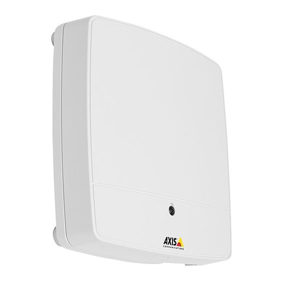
Axis A1001 Installation Manual
Network door controller
Hide thumbs
Also See for A1001:
- Installation manual (210 pages) ,
- User manual (73 pages) ,
- Quick reference (28 pages)
Advertisement
Quick Links
Advertisement

Summary of Contents for Axis A1001
- Page 1 INSTALLATION GUIDE AXIS A1001 Network Door Controller...
-
Page 2: Equipment Modifications
• Connect the equipment into an outlet on a circuit different The Axis product should be installed on a wall (preferred) or a from that to which the receiver is connected. -
Page 3: Contact Information
Directive 2012/19/EU on waste electrical • The Axis product shall be used in compliance with local and electronic equipment (WEEE) is applicable in laws and regulations. - Page 4 Battery The Axis product uses a 3.0 V CR2032 lithium battery as the power supply for its internal real-time clock (RTC). Under normal conditions this battery will last for a minimum of five years.
- Page 5 Please keep this document for future reference. Label here ©2006-2013 Axis Communications AB. Axis is a registered trademark. All other company names and products are trademarks or registered trademarks of their respective companies. We reserve the right to introduce modifications without notice.
- Page 6 Page 6 AXIS A1001 Installation Guide...
- Page 7 AXIS A1001 Installation Guide Page 7...
- Page 8 Page 8 AXIS A1001 Installation Guide Power over Ethernet IEEE 802.3af/802.3at Type 1 Class 3...
- Page 9 AXIS A1001 Installation Guide Page 9 192.168.0.90 AXIS IP Utility www.axis.com/techsup...
- Page 10 Page 10 AXIS A1001 Installation Guide...
- Page 11 AXIS A1001 Installation Guide Page 11...
- Page 12 Page 12 AXIS A1001 Installation Guide...
- Page 13 AXIS A1001 Installation Guide Page 13...
- Page 14 Page 14 AXIS A1001 Installation Guide...
-
Page 15: Auxiliary Connector
AXIS A1001 Installation Guide Page 15 AWG 28–16 (CSA) AWG 30–14 (CUL/UL) READER I/0 1 &2 Power & Relay connector DC output: 12 V DC, max 500 mA Relay: 30 V DC, max 700 mA RELAY & PWR LOCK Power connector Auxiliary connector DC input: 10–30 V DC, DC output: 3.3 V DC, max 100 mA... - Page 16 Page 16 AXIS A1001 Installation Guide Power over Ethernet IEEE 802.3af/802.3at Type 1 Class 3...
- Page 17 AXIS A1001 Installation Guide Page 17...
- Page 18 Page 18 AXIS A1001 Installation Guide www.axis.com/warranty...
- Page 20 Installation Guide Ver.1.1 Printed: November 2013 AXIS A1001 Network Door Controller © Axis Communications AB, 2013 Part No. 54595...


Need help?
Do you have a question about the A1001 and is the answer not in the manual?
Questions and answers