Table of Contents
Advertisement
Advertisement
Table of Contents

Related Manuals for Axis A1601


Summary of Contents for Axis A1601
- Page 1 AXIS A1601 Network Door Controller Installation Guide...
- Page 2 Every care has been taken in the preparation of this Regulatory information document. Please inform your local Axis office of any Europe inaccuracies or omissions. Axis Communications AB cannot be held responsible for any technical or typographical errors and reserves the right to make changes to the product and manuals without prior notice.
- Page 3 Limited Power Source (LPS) according to clause 2.5 of Fax: +46 46 13 61 30 IEC/EN/UL 60950-1 or annex Q of IEC/EN/UL 62368-1. axis.com We recommend the use of Axis PoE+ midspans or Axis PoE+ switches. Warranty information For information about Axis’ product warranty and thereto When the battery input is used, an external 3 A slow blow related information, go to axis.com/warranty...
- Page 4 • find answers to resolved problems in the FAQ database, search by product, category, or phrase • report problems to Axis support staff by logging in to your private support area • chat with Axis support staff •...
- Page 5 AXIS A1601 Network Door Controller...
- Page 6 AXIS A1601 Network Door Controller...
- Page 7 AXIS A1601 Network Door Controller...
- Page 8 AXIS A1601 Network Door Controller...
- Page 9 AXIS A1601 Network Door Controller...
- Page 10 AXIS A1601 Network Door Controller...
- Page 11 AXIS A1601 Network Door Controller...
- Page 12 AXIS A1601 Network Door Controller...
- Page 13 AXIS A1601 Network Door Controller...
- Page 14 AXIS A1601 Network Door Controller...
- Page 15 AXIS A1601 Network Door Controller...
- Page 16 AXIS A1601 Network Door Controller...
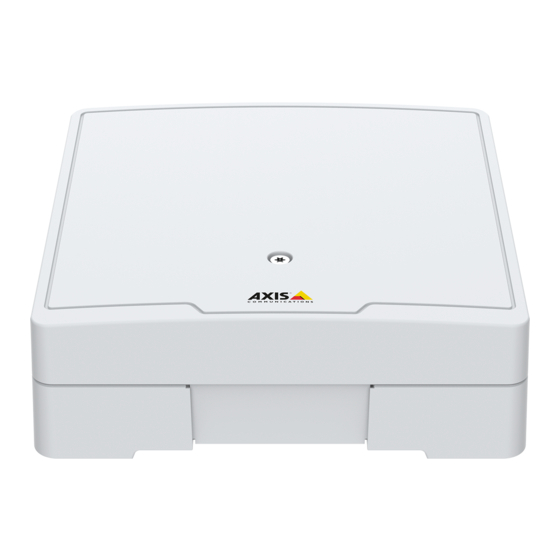
- Page 17 AXIS A1601 Network Door Controller Product overview Door connector on page 23 (2x) Reader connector on page 20 (2x) Control button on page 20 Reader overcurrent LED Relay overcurrent LED Auxiliary connector on page 24 Relay connector on page 23 (2x)
- Page 18 AXIS A1601 Network Door Controller 13 Status LED 14 Network LED 15 Network connector on page 20 16 External connector on page 26 17 Reversible cable cover 18 Grounding position...
- Page 19 AXIS A1601 Network Door Controller Specifications To find the latest version of the product’s datasheet, go to the product page at axis.com and locate Support & Documentation. Text marked with UL is only valid for UL 293 or UL 294 installations.
- Page 20 802.3af/802.3at Type 1 Class 3 or Power over Ethernet Plus (PoE+) IEEE 802.3at Type 2 Class 4 power limited injector that provides 44–57 V DC, 15.4 W / 30 W. Power over Ethernet (PoE) has been evaluated by UL with AXIS T8133 Midspan 30 W 1-port. Reader connector Two 8–pin terminal blocks supporting both RS485 and Wiegand protocols for communication...
- Page 21 AXIS A1601 Network Door Controller 5–6 Full duplex: TX. 7–8 Digital input — 0 to max 30 V DC Configurable (Input or Connect to pin Output) 1 to activate, or leave floating (unconnected) to deactivate. Digital output — 0 to max 30 V DC,...
- Page 22 AXIS A1601 Network Door Controller 7–8 Digital input — 0 to max 30 V DC Configurable (Input or Connect to pin Output) 1 to activate, or leave floating (unconnected) to deactivate. Digital output — 0 to max 30 V DC,...
- Page 23 AXIS A1601 Network Door Controller Door connector Two 4-pin terminal blocks for door monitoring devices (digital input). Only door monitor supports supervision with end of line resistors. If the connection is interrupted, an alarm is triggered. To use supervised inputs, install end of line resistors. Use the connection diagram for supervised inputs.
- Page 24 AXIS A1601 Network Door Controller Normally open. Max current = 2 A per For connecting relay devices. Connect relay a fail-secure lock between NO and DC Max voltage = 30 V DC ground. The two relay pins are galvanically separated from the rest of the circuitry if the jumpers are not used.
- Page 25 AXIS A1601 Network Door Controller 6–pin terminal block Function Notes Specifications DC ground 0 V DC DC output Can be used to power auxiliary equipment. 12 V DC Note: This pin can only be used as power out. Max load = 50 mA for each I/O 3–...
- Page 26 AXIS A1601 Network Door Controller Configurable I/O External connector 4-pin terminal block for external devices, for example glass break or fire detectors. UL: The connector has not been evaluated by UL for burglar/fire alarm use. Function Notes Specifications 1, 3...
- Page 27 AXIS A1601 Network Door Controller UL: DC power to be supplied by a UL 294, UL 293 or UL 603 listed power supply, depending on application, with appropriate ratings. Backup battery input connector For a backup solution using a battery with built-in charger. 12 V DC input.
- Page 28 • For UL 294, compatibility with the following readers has been verified by UL: HID iClass RK40, AXIS A4010-E. For UL 293 applications, readers must be listed to UL 293. UL has not verified any UL 293 readers. Safety instructions •...
- Page 29 (PoE is not allowed). The lock(s) must be supplied by external voltage (12 V DC or 24 V DC supplied by the A1601 is disallowed). Only one reader connected with maximum average current of 130 mA at 12 V. •...
- Page 30 2 low-voltage power SELV and limited power supply. Network Connector – Standard Ethernet wiring. Evaluated by UL when powered from AXIS T8133 Midspan 30 W 1-port in PoE Mode B. Do not use for UL 293 installations. Battery input is for connection to a listed UPS and has not been evaluated by UL to UL 294 or UL 293.
- Page 31 CAUTION Battery The Axis product uses a 3.0 V CR2032 lithium battery as the Indicates a hazardous situation which, if not avoided, could result in minor or moderate injury. power supply for its internal real-time clock (RTC). Under...
- Page 32 • Conserver ce produit Axis dans un environnement sec et ventilé. • Ne pas exposer ce produit Axis aux chocs ou aux fortes Deutsch pressions. • Ne pas exposer ce produit Axis aux vibrations.
- Page 33 Bei Bedarf transportieren Sie das Axis Produkt in alle leggi e alle normative locali. der Originalverpackung oder einer entsprechenden • Axis consiglia l'uso di un cavo di rete schermato (STP). Verpackung, so dass Schäden vermieden werden. • Per utilizzare il dispositivo Axis in ambienti esterni o in...
- Page 34 (RTC) interno. In condizioni normali questa batteria avrà ventilado. una durata minima di cinque anni. • Evite la exposición del producto de Axis a choques o a una fuerte presión. Una bassa carica della batteria influisce sul funzionamento • Evite la exposición del producto de Axis a vibraciones.
- Page 35 材質 (⽊材、⾦属、シートロック、⽯材など) に • consulte la página web del producto o póngase en contacto 適したネジとプラグを使⽤して本製品を設置し con el soporte técnico de Axis. てください。 Las pilas de botón de litio de 3,0 V contienen 本製品を不安定なポール、ブラケット、表⾯、 •...
- Page 36 Português • Não tente reparar o produto por conta própria. Entre em contato com o suporte ou seu revendedor Axis para quaisquer questões relacionadas a serviços. • Informações sobre segurança A fonte de alimentação deve ser conectada em uma tomada elétrica instalada próxima ao produto e deverá...
- Page 37 • Не пытайтесь отремонтировать устройство 表示如果不避免则可能导致财产损失的情况。 самостоятельно. По вопросам обслуживания обращайтесь в службу поддержки Axis или к своему 其 其 其 他 他 他 消 消 消 息 息 息 等 等 等 级 级 级 реселлеру Axis. 重要 •...
- Page 38 하십시오. 한국어 • 제품을 직접 수리하려고 하지 마십시오. 서비 스 문제에 대해 Axis 지원 부서 또는 Axis 리셀러 에 문의하십시오. 전원 공급 장치는 제품 근처에 설치된 소켓 콘센 • 안 안 안 전 전 전 정 정 정 보 보 보...
- Page 39 • Axis 제품을 운반할 때는 원래 포장이나 이에 준 하는 포장을 사용해 제품이 손상되지 않도록 하 십시오. 배 배 배 터 터 터 리 리 리 Axis 제품은 3.0V CR2032 리튬 배터리를 내부 RTC(real-time clock)의 전원으로 사용합니다. 정 상 조건에서 이 배터리는 최소 5년간 사용할 수 있...
- Page 40 Installation Guide Ver. M4.15 AXIS A1601 Network Door Controller Date: May 2019 © Axis Communications AB, 2018 - 2019 Part No. 1987694...
Need help?
Do you have a question about the A1601 and is the answer not in the manual?
Questions and answers