Konica Minolta Di1610 Service Manual
Hide thumbs
Also See for Di1610:
- User manual (148 pages) ,
- User manual (136 pages) ,
- Service manual (292 pages)
Table of Contents
Advertisement
Quick Links
Download this manual
See also:
User Manual
Advertisement
Chapters
Table of Contents
Troubleshooting

Subscribe to Our Youtube Channel
Related Manuals for Konica Minolta Di1610


Summary of Contents for Konica Minolta Di1610
- Page 1 SERVICE MANUAL FIELD SERVICE Di1610 2003.11 Ver. 1.0...
- Page 2 SAFETY PRECAUTIONS FOR INSPECTION AND SERVICE • When performing inspection and service procedures, observe the following precautions to prevent accidents and ensure utmost safety. ✽ Depending on the model, some of the precautions given in the following do not apply. •...
- Page 3 WARNING 2. Before starting the procedures, be sure to unplug the power cord. • This product contains a high-voltage unit and a circuit with a large current capacity that may cause an electric shock or burn. • The product also contains parts that can jerk suddenly and cause injury. •...
- Page 4 WARNING 8. Do not touch a high-temperature part. • A part marked with the symbol shown on the left and other parts such as the exposure lamp and fusing roller can be very hot while the machine is ener- gized. Touching them may result in a burn. •...
- Page 5 CAUTION 2. Precautions for Servicing with Covers and Parts Removed. • Wherever feasible, keep all parts and covers mounted when energizing the product. • If energizing the product with a cover removed is absolutely unavoidable, do not touch any exposed live parts and use care not to allow your clothing to be caught in the moving parts.
- Page 6 1-3. Used Batteries Precautions ALL Areas CAUTION Danger of explosion if battery is incorrectly replaced. Replace only with the same or equivalent type recommended by the manufacturer. Dispose of used batteries according to the manufacturer’s instructions. Germany VORSICHT! Explosionsgefahr bei unsachgemäßem Austausch der Batterie. Ersatz nur durch denselben oder einen vom Hersteller empfohlenen gleichwertigen Typ.
-
Page 7: Other Precautions
1-4. Other Precautions • When handling circuit boards, observe the “HANDLING of PWBs”. • The PC Drum is a very delicate component. Observe the precautions given in “HAN- DLING OF THE PC DRUM” because mishandling may result in serious image problems. •... - Page 8 4. Precautions for Dis/Reassembly • Be sure to unplug the copier from the outlet before attempting to service the copier. • The basic rule is not to operate the copier anytime during disassembly. If it is absolutely necessary to run the copier with its covers removed, use care not to allow your clothing to be caught in revolving parts such as the timing belt and gears.
- Page 9 8. Handling of the PC Drum ✽ Only for Products Not Employing an Imaging Cartridge. During Transportation/Storage • Use the specified carton whenever moving or storing the PC Drum. • The storage temperature is in the range between –20°C and +40°C. •...
- Page 10 C. Soak a small amount of either ethyl alcohol or iso- propyl alcohol into a clean, unused Dust-Free Cot- ton Pad which has been folded over into quarters. Now, wipe the surface of the PC Drum in one con- tinuous movement from its rear edge to its front edge and off its surface one to two times.
- Page 11 INDEX (Field Service) GENERAL MAINTENANCE DIS/REASSEMBLY, ADJUSTMENT CONTROL PANEL/SERVICE MODE DESCRIPTIONS TROUBLESHOOTING...
-
Page 12: Table Of Contents
CONTENTS GENERAL 1. SPECIFICATIONS ...................G-1 (1) Main Unit ..................G-1 (2) GDI Printer Function ................G-3 2. PRECAUTIONS FOR INSTALLATION ............G-4 2-1. Installation Site ..................G-4 2-2. Power Source ...................G-4 3. PRECAUTIONS FOR USE ................G-5 3-1. To Ensure the Printer is Used in an Optimum Condition ......G-5 3-2. - Page 13 (4) Removal of the Power Unit .............. D-12 (5) Removal of the High Voltage Unit ........... D-14 3-3. Removal of Units ..................D-15 (1) Removal of the IR Unit ..............D-15 (2) Removal of the PH Unit ..............D-16 3-4. Disassembly of the Image Reading Section ..........D-18 (1) Removal of the Original cover set sensor ........
- Page 14 (1) Machine Setting ................S-6 (2) Paper Source Setting ...............S-8 (3) Copy Setting ..................S-8 4. SERVICE MODE ....................S-9 4-1. Service Mode Function Tree ..............S-9 4-2. Service Mode Setting Procedure .............S-11 4-3. Service Mode Functions ................S-12 (1) Service's Choice ................S-12 (2) Adjust .....................S-14 (3) Counter ....................S-17 (4) Display .....................S-19 (5) Function ...................S-19...
- Page 15 (11) C13F0: Laser error ................T-21 (12) C1468: EEPROM error ..............T-21 (13) C14A3: IR lamp malfunction ............T-22 4. MALFUNCTIONS RELATED TO POWER SUPPLY ........T-23 4-1. Power is not Turned ON................T-23 5. IMAGE QUALITY PROBLEMS ................ T-24 5-1.
-
Page 16: General
GENERAL... -
Page 17: Specifications
SPECIFICATIONS Main Unit Type Desktop Original scanning system Scanning in main scanning direction with a 3-line color CCD sensor, and scanning in sub-scanning direction with unit scanning and sheet feed-through system Photoconductor type OPC (Organic Photoconductor) Copying system Electrostatic dry Powdered image transfer to plain paper with laser 600 dpi ×... - Page 18 12 copies/minute (at full size and 600 dpi × 300 dpi, with Continuous copy speed (copies/min.) ADF) Continuous print speed More than 16 sheets/minute (with plain A4 L or Letter L (sheets/min.) paper) Warm-up time Less than 25 seconds (at a room temperature of 23 °C and at the rated voltage) 16 seconds or less (at full size and 600 dpi ×...
-
Page 19: Gdi Printer Function
Zoom Ratios Metric Size English Size ×1.00 ×1.00 Full size ×1.15 ×1.29 ×1.41 ×1.54 Enlargement ×2.00 ×2.00 Fixed ×0.81 ×0.78 ×0.70 ×0.64 Reduction ×0.50 ×0.50 ×0.50 to ×2.00 (in ×0.01 increments) Variable Lens Through lens (F=5.0, f=27.195) Exposure Lamp Cold Cathode Florescent Lamp Fusing temperature 200 °C Power /Current Consumption (main unit only) -
Page 20: Precautions For Installation
PRECAUTIONS FOR INSTALLATION 2-1. Installation Site To ensure utmost safety and avoid breakdown, the printer should NOT be used in a place: • Where it will be subjected to extremely high or low temperature or humidity. • Where it will be subjected to sudden fluctuations in either temperature or humidity. •... -
Page 21: Precautions For Use
PRECAUTIONS FOR USE 3-1. To Ensure the Printer is Used in an Optimum Condition • Never place a heavy object on the printer or subject the printer to shocks. • Insert the power plug all the way into the outlet. •... -
Page 22: Handling Of The Consumables
HANDLING OF THE CONSUMABLES Before using any consumables, always read the label on its container carefully. • Paper can easily damp. To prevent absorption of moisture, store paper in a place with lit- tle moisture. • Keep consumables out of the reach of children. •... -
Page 23: Parts Identification
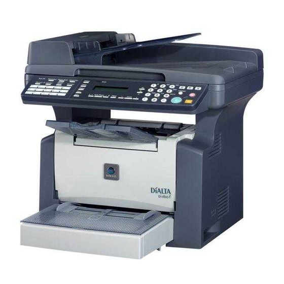
PARTS IDENTIFICATION 4980G001AA 1. Automatic Document Feeder AF-11 4. Paper Feed Cassette PF-125 2. Mechanical Counter 5. Main Unit Di1610 3. Expansion memory 32-5 (32 MB) 6. Original Cover OC-7... - Page 24 MAINTENANCE...
-
Page 25: Maintenance Schedule
MAINTENANCE SCHEDULE • To ensure that the printer produces good printed pages and to extend its service life, it is recommended that the maintenance jobs described in this schedule be carried out as instructed. Ref. Page PM Parts Clean Replace 1 Replace 2 in This Manual... -
Page 26: Guidelines For Life Specifications Values By Unit
1-1. Guidelines for Life Specifications Values by Unit • The life specifications value represents the number of printed pages produced or figures equivalent to it when given conditions (see the Table given below) are met. It can be more or less depending on how each individual printer is used. Print Conditions Job type 2P/J... -
Page 27: Replacement/Cleaning Of Parts
REPLACEMENT/CLEANING OF PARTS Cleaning of the Paper Take-Up Roll 1. Remove the Imaging Cartridge. ☞ E-5 NOTE • The Imaging Cartridge is the Drum Cartridge, to which the Toner Cartridge is mounted. 2. Using a soft cloth, wipe the surface of the Paper Take-Up Roll clean of dirt. -
Page 28: Replacement Of The Image Transfer Roller
Replacement of the Image Transfer Roller 1. Remove the Imaging Cartridge. ☞ E-5 2. Place the levers of the bushings (white) on the right and left ends of the Image Transfer Roller toward this side and remove the Image Transfer Roller from the Image Transfer Roller holder. -
Page 29: Replacement Of Units
REPLACEMENT OF UNITS Replacement of the Toner Cartridge <Removal Procedures> 1. Lift up the Exit Tray and remove it. 2. Open the Front Door. 4980E009AA 3. Remove the Imaging Cartridge. 4136E006AA 4. Pull the lever of the Toner Cartridge in the direc- tion shown in the illustration and disconnect the Toner Cartridge from the Drum Cartridge. - Page 30 2. Remove the protective cover from the Toner Car- tridge. C4136o049AC 3. Install the new Toner Cartridge to the Drum Car- tridge. NOTE • Insert the Toner Cartridge along the guide pro- vided on the Drum Cartridge side and make sure that the Toner Cartridge is not tilted when inserted.
-
Page 31: Replacement Of The Drum Cartridge
Replacement of the Drum Cartridge <Removal Procedures> 1. Remove the Imaging Cartridge. ☞ E-5 2. Pull the lever of the Toner Cartridge in the direc- tion shown in the illustration and disconnect the Drum Cartridge. 4136E011AC <Installation Procedures> 1. Mount the Toner Cartridge to a new Drum Car- tridge. -
Page 32: Replacement Of The Fusing Unit
Replacement of the Fusing Unit NOTE • Immediately after turning off the printer, the area around the Fusing Unit is extremely hot. Therefore, in order to reduce the risk of burns, wait until the unit has cooled down before performing any operation. <Removal Procedures>... - Page 33 7. Remove two screws, unplug three connectors, and remove the Fusing Unit. NOTE • The surfaces around the Fusing Unit are very hot. Use utmost care not to touch any surfaces other than the Fusing Unit. 4980E002AB 8. Remove the Fusing Unit. 4980E003AA <Installation Procedures>...
-
Page 34: Dis/Reassembly, Adjustment
DIS/REASSEMBLY, ADJUSTMENT... -
Page 35: Safety Information
SAFETY INFORMATION 1-1. Laser Safety • This is a digital machine certified as a class 1 laser product. There is no possibility of danger from a laser, provided the machine is serviced according to the instruction in this manual. 1-2. Internal Laser Radiation Semiconductor laser Maximum power of the laser diode... - Page 36 the U.S.A., Canada (CDRH Regulation) • This machine is certified as a Class I Laser product under Radiation Performance Stan- dard according to the Food, Drug and Cosmetic Act of 1990. Compliance is mandatory for Laser products marketed in the United States and is reported to the Center for Devices and Radiological Health (CDRH) of the U.S.
- Page 37 Finland, Sweden VARO! Avattaessa ja suojalukitus ohitettaessa olet alttiina näkymättömälle lasersäteilylle. Älä katso säteeseen. LOUKAN 1 LASERLAITE KLASS 1 LASER APPARAT VAROITUS! Laitteen Käyttäminen muulla kuin tässä käyttöohjeessa mainitulla tavalla saattaa altistaa käyttäjän turvallisuusluokan 1 ylittävälle näkymättömälle lasersäteilylle. Puolijohdelaser Laserdiodin suurin teho 15 mW Aallonpituus 770-800 nm...
-
Page 38: Laser Safety Label
1-3. Laser Safety Label • A laser safety labels is attached to the outside of the machine as shown below. 4980D070AB 1-4. Laser Caution Label • A laser caution label is attached to the inside of the machine as shown below. 4980D061AA... -
Page 39: Precautions For Handling The Laser Equipment
1-5. Precautions for Handling the Laser Equipment • When laser protective goggles are to be used, select ones with a lens conforming to the above specifications. • When a disassembly job needs to be performed in the laser beam path, such as when working around the printerhead and PC Drum, be sure first to turn the copier OFF. -
Page 40: Precautions For Disassembly/Adjustments
PRECAUTIONS FOR DISASSEMBLY/ADJUST- MENTS 2-1. Parts That Must Not be Touched Red Painted Screws Purpose of Application of Red Paint Red painted screws show that the assembly or unit secured can only be adjusted or set at the factory and shall not be readjusted, set, or removed in the field. If it becomes unavoidably necessary to disassemble any of these assemblies and units, disassembly may be done provided that the conditions permitting reassembly are met. -
Page 41: Disassembly/Reassembly
DISASSEMBLY/REASSEMBLY 3-1. Identification of Exterior Parts and Removal Procedures for Them C4980o003AC C4980o057AB... - Page 42 Name Removal Procedure Open the Original Cover → Pull it straight up. Original Cover Remove the Original Cover. → Remove the Control Panel. → Remove the six screws, and remove the Upper Upper Cover Assy. (Original Glass) Cover Assy. (Original Glass). ☞...
-
Page 43: Removal Of Circuit Boards And Other Electrical Components
3-2. Removal of Circuit Boards and Other Electrical Components NOTES • When removing a circuit board or other electric component, refer to the precautions for handling PWBs and follow the corresponding removal procedures. • The removal procedures given in the following paragraphs omit the removal of the com- ponent in question from a connector or a PWB support. -
Page 44: Removal Of The Controller/Mechanical Control Board
Removal of the Controller/Mechanical Control Board <Removal Procedures> 1. Remove the Rear Cover. 2. Disconnect all connectors and flat cables from the Controller/Mechanical Control Board. NOTE • Use utmost care not to snap off the flat cable. 4980D003AB 3. Remove six screws and the Controller/Mechani- cal Control Board. -
Page 45: Removal Of The Interface Board
Removal of the Interface Board 1. Remove the Rear Cover. ☞ D-7 2. Unplug the three connectors on the Controller/ Mechanical Control Board. 4980D063AA 3. Remove the two screws, and then remove the Left Rear Cover. 4980U044AA 4. Remove the three screws, and then remove the Circuit Board and Metal Bracket. -
Page 46: Removal Of The Power Unit
Removal of the Power Unit 1. Remove the Right Cover. ☞ D-7 2. Remove the Left Cover. ☞ D-7 3. Remove the Rear Cover. ☞ D-7 4. Unplug the two flat cables from the Controller/ Mechanical Control Board. NOTE • Use utmost care not to snap off the flat cable. 4980D006AA 5. - Page 47 9. Remove the three screws, unhook the tab, and then remove the Left Rear Frame. 4980D009AB 10. Remove the three screws from the Left Rear Frame. 4980D071AA 11. Remove the four screws, and then remove the Metal Bracket. 4980D072AA 12. Remove the two screws, unhook the tab, and then remove the Left Rear Frame.
-
Page 48: Removal Of The High Voltage Unit
15. Remove the two screws, unplug the three con- nectors, and then remove the Fusing Unit Assy. 4980E002AA 16. Remove three screws and the Power Switch stay. 17. Remove the Power Switch. 4980D011AC 18. Remove four screws, disconnect three connec- tors, and remove the Power Unit Assy. -
Page 49: Removal Of Units
3-3. Removal of Units Removal of the IR Unit 1. Remove the Left Cover. ☞ D-7 2. Remove the Right Cover. ☞ D-7 3. Remove the Rear Cover. ☞ D-7 4. Unplug the connector. 4980D007AA 5. Unplug the two flat cables from the Controller/ Mechanical Control Board. -
Page 50: Removal Of The Ph Unit
Removal of the PH Unit NOTES • NEVER attempt to replace the PH Unit with power being supplied to the printer. Doing that could lead to exposure to the laser beam, resulting in blindness • NEVER attempt to disassemble or adjust the PH Unit. Doing that could lead to exposure to the laser beam, resulting in blindness. - Page 51 Precautions for Removal/Reinstallation of the PH Unit • NEVER touch the window on the backside of the PH Unit. A dirty window can cause an image problem. Window 4136D009AB D-17...
-
Page 52: Disassembly Of The Image Reading Section
3-4. Disassembly of the Image Reading Section Removal of the Original cover set sensor 1. Remove the Original Cover. 2. Remove the Control Panel. ☞ D-7 3. Remove the Original cover set sensor. 4980D073AA Removal of the Upper Cover Assy. (Original Glass) 1. -
Page 53: Removal Of The Scanner Assy
5. Remove the two screws, and then remove the Scanner Motor Mounting Bracket. 4980D018AB 6. Remove the two screws, and then remove the Scanner Motor. 4980D019AA Removal of the Scanner Assy. 1. Remove the Original Cover. 2. Remove the Upper Cover Assy. (Original Glass). ☞... -
Page 54: Removal Of The Timing Belt
5. Remove the Timing Belt and shaft, and then remove the Scanner Assy. 4980D022AA Removal of the Timing Belt 1. Remove the Original Cover. 2. Remove the Upper Cover Assy. (Original Glass). ☞ D-18 3. Remove the Scanner Assy. ☞ D-19 4. -
Page 55: Disassembly Of The Main Drive Section
3-5. Disassembly of the Main Drive Section Removal of the Main Motor 1. Remove the Left Cover. 2. Disconnect one connector. 3. Remove two screws, two washers, and the Main Motor. 4136D010AB Removal of the Paper Empty Sensors 1. Remove the Imaging Cartridge. 2. - Page 56 6. Unhook two tabs and remove the tray. 4980D027AC 7. Remove the Multi purpose Tray Paper Empty Sensor. 4980D028AB 8. Remove the Multiple Bypass Tray Paper Empty Sensor. 4980D029AB 9. Remove the Toner Empty detection sensor. 4980D030AA D-22...
-
Page 57: Removal Of The Paper Take-Up Solenoid
Removal of the Paper Take-Up Solenoid 1. Remove the Left Cover. ☞ E-8 2. Disconnect one connector of the Paper Take-Up Solenoid. 4136D058AA 3. Remove one screw and the Paper Take-Up Sole- noid. 4136D059AA Precautions for Installation of the Paper Take-Up Solenoid 1. -
Page 58: Removal Of The Paper Take-Up Clutch Gear
Removal of the Paper Take-Up Clutch Gear 1. Remove the Fusing Unit. ☞ E-8 2. Remove the Power Unit. ☞ D-12 3. Remove the Paper Take-Up Upper Guide Assy. ☞ D-21 4. Disconnect one connector and remove the Cool- ing Fan Motor 2. 5. -
Page 59: Removal Of The Torque Limiter
12. Remove one screw and the Paper Take-Up Sole- noid. 4136D018AA 13. Unhook two tabs and remove the Paper Take-Up Clutch Gear. 4136D057AA Removal of the Torque Limiter 1. Remove the Paper take up Clutch Gear. ☞ D-24 2. Unhook three tabs and take apart the Paper Torque Limiter Take-Up Clutch Gear then, remove the Torque Coupling... -
Page 60: Disassembly Of The Fusing Unit
After setting replaced Paper Take-Up Clutch Gear (Torque Limiter) to the shaft, Rotate the Paper Take- Up Clutch Gear by hand (Need to be released Sole- noid Flapper). 4136D060AA Look at the stop position of the Take-Up Roller from Clutch Gear side. 1. - Page 61 3. Remove two bushings and the Pressure Roller. Lower Fusing Roller section 4136D022AA Upper Fusing Precautions for Installation of Bushings Roller • Make sure that the slits in the bushing are properly section aligned with the rib of the Fusing Unit. 4136D040AA 4.
- Page 62 9. Remove one screw and the Thermistor. NOTE • When reinstalling the Thermistor, route the har- ness as shown in the illustration. 10. Remove two screws and the Thermostat. 4980D068AA D-28...
-
Page 63: Adjustments
ADJUSTMENTS 4-1. Electrical/Image Adjustment Accessing the Service Mode 1. Press the Utility key. 2. Press the following keys in order to enter the Service mode. Stop → 0 → 0 → Stop → 0 → 1 NOTE • Be sure to keep the access procedure for the Service mode from any unauthorized per- sons not involved with service operations. -
Page 64: Margin Adjustment (Leading Edge/Trailing Edge/Both Sides
Margin Adjustment (Leading Edge/Trailing Edge/Both Sides) <Requirement> • Specify the amount erased at the leading edge (width of A), trailing edge (width of B), and both sides (width of C) of the paper. • Default setting: 4 mm 4022D503AA Mode Function Item Setting Range Leading Edge Erase... -
Page 65: Printer's Main Scanning Registration Adjustment
Printer’s Main Scanning Registration Adjustment <Requirement> • Adjust the amount that widths A and B in the printed test pattern are shifted so that the following specification is met. 1382D011AA Specification Mode Function Item Setting Range 60 to 140 0±2.0 mm “ADJUST”... -
Page 66: Printer's Sub-Scanning Registration Adjustment
Printer’s Sub-Scanning Registration Adjustment <Requirement> • Adjust the width of C in the printed test pattern so that the following specification is met. 4007D051AA Specification Mode Function Item Setting Range 87 to 113 20±2.5 mm “ADJUST” menu PRN SUB REGIST 1 increment = 0.46 mm Perform this adjustment in the following cases. -
Page 67: Scanner's Main Scanning Zoom Ratio Adjustment
Scanner’s Main Scanning Zoom Ratio Adjustment <Requirement> • After finishing the printer’s main scanning & sub- scanning registration adjustments, place the printed test pattern on the Original Glass, and make a copy of it. • Adjust the width of D in the copy of the test pattern so that the following specification is met. - Page 68 NOTE If the Stop key is pressed, instead of the Yes key, the main screen is displayed and the set- ting returns to that before it was changed. Place the test pattern on the Original Glass again, make another test copy, and check it. D-34...
-
Page 69: Scanner's Sub-Scanning Zoom Ratio Adjustment
Scanner’s Sub-Scanning Zoom Ratio Adjustment <Requirement> • After finishing the printer’s main scanning & sub- scanning registration adjustments, place the printed test pattern on the Original Glass, and make a copy of it. • Adjust the width of E in the copy of the test pattern so that the following specification is met. - Page 70 NOTE If the Stop key is pressed, instead of the Yes key, the main screen is displayed and the set- ting returns to that before it was changed. Place the test pattern on the Original Glass again, make another test copy, and check it. D-36...
-
Page 71: Scanner's Main Scanning Registration Adjustment
Scanner’s Main Scanning Registration Adjustment <Requirement> • After finishing the printer’s main scanning & sub- scanning registration adjustments, place the printed test pattern on the Original Glass, and make a copy of it. • Adjust the width of E in the copy of the test pattern so that the following specification is met. - Page 72 NOTE If the Stop key is pressed, instead of the Yes key, the main screen is displayed and the set- ting returns to that before it was changed. Place the test pattern on the Original Glass again, make another test copy, and check it. D-38...
-
Page 73: (10) Scanner's Sub-Scanning Registration Adjustment
(10) Scanner’s Sub-Scanning Registration Adjustment <Requirement> • After finishing the printer’s main scanning & sub- scanning registration adjustments, place the printed test pattern on the Original Glass, and make a copy of it. • Adjust the width of C in the copy of the test pattern so that the following specification is met. -
Page 74: Miscellaneous
MISCELLANEOUS 5-1. Removal of the Mechanical Counter (Option) 1. Remove the Right Cover. ☞ D-7 2. Remove the Rear Cover. ☞ D-7 3. Unplug one connector on the Controller/Mechani- cal Control Board. 4980D055AA 4. Remove the Relay Harness. 4980D056AA 5. Remove the screw, and then remove the Mechanical Counter. -
Page 75: Updating The Firmware
5-2. Updating the Firmware NOTES • The TWAIN driver must already be installed on the host computer to be used for updating the firmware. • If the GDI printer or TWAIN driver is not installed, follow the procedure described below to install the driver. - Page 76 <For Windows Me/98/95> 1. Start up the host computer, and then insert the CD-ROM into the CD-ROM drive. 2. Turn on the printer. 3. Use a USB cable to connect the printer to the host computer. 4. In the “Install Hardware Device Drivers” dialog box, click the [Next] button, select “Search for a suitable driver for my device (recommended)”, and then click the [Next] button again.
-
Page 77: Procedure For Updating The Gdi Firmware
5. Display the “System Properties” dialog box (“Properties” for “My Computer”), click the “Hardware” tab, click the [Device Manager] button, select “Imaging devices”, and then check that “Minolta Di1610” has been added. 4980D045AA 4980D046AA 6. Double-click “Update” file in the “Update Software” folder. - Page 78 8. Click the [Update] button. The transfer of firmware data begins. (Wait until the transfer of data is finished.) 9. Check the firmware update status in the display. 4980D050AB NOTE • Do not turn the printer off or on while the screen shown above is displayed. 10.
-
Page 79: Remedy For A Failed Updating Of The Firmware
5-4. Remedy for a Failed Updating of the Firmware 1. Turn off the printer. 2. Remove the USB cable connecting the printer to the host computer. 3. Remove the Rear Cover. ☞ D-7 4. Change the settings for jumper switches CJ1 and CJ2 on the Controller/Mechanical Control Board from “1-2”... - Page 80 8. Turn on the printer. The following message appears in the display. 4980D053AA 9. Perform steps 6 through 10 of “Procedure for Updating the GDI Firmware” to update the firmware. 10. Check that the following message appears in the display to indicate that the updating of the firmware has been completed correctly.
-
Page 81: Moving The Eeprom
5-5. Moving the EEPROM NOTE • After the Controller/Mechanical Control Board (PWB-P) is replaced, be sure to move the EEPROM form the old Controller/Mechanical Control Board to the new one. Remove the EEPROM (U39) from the old Controller/Mechanical Control Board, and then attach it to the new Controller/Mechanical Control Board. -
Page 82: Control Panel/Service Mode Descriptions
CONTROL PANEL/SERVICE MODE DESCRIPTIONS... -
Page 83: Control Panel Descriptions
CONTROL PANEL DESCRIPTIONS 1-1. Names of Control Panel Parts and Their Functions 4980S001AA Key Name Function Printer key Press to enter Printer mode. Utility key Press to enter Utility mode. The indicator lights up if an error or malfunction Error lamp occurs. - Page 84 Key Name Function • Press to change the zoom ratio between ×0.50 ▲ / ▼ key and ×2.00 in ×0.01 increments. • Press to show the various settings and informa- tion. • Press to specify various settings. Press to select a zoom ratio from the preset fixed Zoom key ratios.
-
Page 85: Functions Of Switches And Parts On Pwbs
FUNCTIONS OF SWITCHES AND PARTS ON PWBs 2-1. Circuit Board Locations PWB-P PWB-IF 4980S002AA 2-2. PWB-P (Controller/Mechanical Control Board) M32-5(Option) Socket 4980S003AB... -
Page 86: Pwb-If (Interface Board
2-3. PWB-IF (Interface Board) IEEE1284 (parallel) port USB port 4980S004AA... -
Page 87: Utility Mode
UTILITY MODE • This mode is used to set various machine functions. 3-1. Utility Mode Function Tree 1:AUTO PANEL RESET 2:ENERGY SAVE MODE 3:DENSITY(ADF) MACHINE SETTING 4:DENSITY(BOOK) 5:PRINT DENSITY 6:LCD CONTRAST 7:LANGUAGE 8:LAMP OFF TIME 1:TRAY1 PAPER UTILITY MODE PAPER SOURCE SETUP 2:TRAY SETTING 1:PAPER PRIORITY 2:DENSITY PRIORITY... -
Page 88: Utility Mode Setting Procedure
3-2. Utility Mode Setting Procedure <Procedure> 1. Press the Utility key. 2. The first Utility mode screen appears. <Exiting Procedure> • Press the Panel Reset key. <Changing the Settings for Utility Mode Functions> 1. Press the Zoom Select key, Density Select key or the 10-Key Pad to select the desired function. - Page 89 Function Purpose Setting Details/Precautions To specify the scanning density • The default setting is when using the Original Glass. “MODE1”. • MODE1: For printing copies with the DENSITY same density as the docu- (BOOK) ment • MODE2: For a lighter copy density in order to reduce the appear- ance of spots in copies To specify the default print density.
-
Page 90: Paper Source Setting
Paper Source Setting • Various settings for the paper tray can be specified. Function Purpose Setting Details/Precautions To specify the type and size of • The default settings are paper loaded into Tray1. “PLAIN” in addition to “A4 L” or “LT”. <Procedure>... -
Page 91: Service Mode
SERVICE MODE • This mode is used to check, specify, adjust and register service functions. 4-1. Service Mode Function Tree SHIPMENT DESTINATION LEADING EDGE ERASE TRAILING EDGE ERASE Service’s Choice VERTICAL EDGE ERASE FLS PAPER SIZE GDI TIMEOUT TONER EMPTY STOP PRE-ROTATION FUSER TEMP.Ad PRN MAIN REGIST... - Page 92 PAPER FEED TEST PRINT TEST PATTERN FUNCTION ADF FEED TEST COPY ADF GLASS AREA CCD MOVE TO HOME SCAN TEST FIXED ZOOM Service Mode PANEL BUZZER TEST FACTORY TEST RAM TEST MEMORY CLEAR PM COUNTER I/C COUNTER CLEAR DATA APPLICATION COUNTER SCAN COUNTER PRINTER JAM COUNTER ADF JAM COUNTER...
-
Page 93: Service Mode Setting Procedure
4-2. Service Mode Setting Procedure NOTE • Be sure to keep the access procedure for the Service mode from any unauthorized per- sons not involved with service operations. <Procedure> 1. Press the Utility key. 2. Press the following keys in order to enter the Service mode. Stop →... -
Page 94: Service Mode Functions
4-3. Service Mode Functions Service's Choice • Various machine service functions can be specified. Function Purpose Setting Details/Precautions To switch the fixed zoom ratios and • The default setting is either SHIPMENT paper sizes according to the “METRIC” or “INCH”. DESTINATION selected marketing area. - Page 95 Function Purpose Setting Details/Precautions To select if the pre-rotation opera- • The default setting is “OFF”. tion for the Fusing Roller is per- formed when the Start key is PRE-ROTATION pressed. • If “OFF” is selected, the length of time until the first copy can be printed is shorter.
-
Page 96: Adjust
Adjust Function Purpose Setting Details/Precautions TEST To vary and adjust the print start Press the Start key to begin COPY position in the main scanning printing the test page. direction. The setting range is 60 to 140. (1 increment = 0.1 mm) MAIN ✽... - Page 97 Function Purpose Setting Details/Precautions TEST To adjust for variations in the accu- Press the Start key to begin COPY racy of IR parts and their mounting printing the test page. accuracy by varying the scanning The setting range is 90 to 110. start position in the sub-scanning (1 increment = 0.5 mm) direction.
- Page 98 Function Purpose Setting Details/Precautions To specify the type of Toner Car- • The default setting differs tridge that should be installed in depending on the marketing the main unit. area. • Once the type of Toner Cartridge Toner Cartridge Type Setting is specified, “TC TYPE”...
- Page 99 Counter • The counter values can be displayed. Function Purpose Setting Details/Precautions To display the total number of COPY: Number of copies pages used. printed PRINT: Number of computer printouts printed TOTAL COUNTER • Test prints made in Service mode to check the operation are not counted.
-
Page 100: Counter
Function Purpose Setting Details/Precautions To display the number of misfeeds • To clear the counter data, use ADF JAM that occurred while using the Auto- the functions on the “CLEAR COUNTER matic Document Feeder. DATA” menu of Service mode. To display the number of times C0045:Fuser fan error each error was detected. -
Page 101: Display
Display • Various information can be displayed. Function Purpose Setting Details/Precautions MAIN F/W VER. To display the version of the main firmware. ENGINE F/W VER. To display the version of the engine firmware. MAIN RAM SIZE To display the size of the main memory. SERIAL NO. - Page 102 Function Purpose Setting Details/Precautions To check for dirt in the scanning <Procedure> section of the Automatic Document 1. Load A4 L or Letter L paper Feeder. into Tray1. 2. Press the Start key to start ✽ If spots appear in the copies the “COPY ADF GLASS AREA”...
-
Page 103: Fixed Zoom Change
Fixed Zoom Change • The fixed zoom ratios can be changed. <Procedure> 1. Select the fixed zoom ratio that you wish to change. 2. Use the 10-Key Pad to type in the desired fixed zoom ratio. Default fixed zoom ratios and setting ranges according to marketing area <Metric>... -
Page 104: Factory Test
Factory Test • Operation tests can be performed during manufacturing. Function Purpose Setting Details/Precautions PANEL BUZZER To check the operation of the display and all indicators and buttons. TEST RAM TEST To test reading and writing of the memory. Clear Data •... -
Page 105: Security Mode
SECURITY MODE • This mode is used to set various security functions. 5-1. Security Mode Function Tree SECURITY MACHINE COUNTER 5-2. Security Mode Setting Procedure NOTE • Be sure to keep the access procedure for the Security mode from any unauthorized per- sons not involved with service operations. -
Page 106: Troubleshooting
TROUBLESHOOTING... -
Page 107: Introduction
INTRODUCTION • This chapter contains the items required or used when troubleshooting various printer problems. 1-1. Electric Components Check Procedures • The following procedures can be used to check to see if an electric component is fully operational when a paper misfeed or a malfunction occurs in the printer. Sensors Step Check... -
Page 108: Switches
Switches Step Check Result Action Replace the switch. Does the input signal (NO) to the Controller/Mechani- Replace the Con- cal Control Board go from LOW to HIGH when the troller/Mechanical switch is actuated? Control Board. Not Use 4025T523AB Solenoids Step Check Result Action... -
Page 109: Motors
Motors Step Check Result Action Replace the Con- Is the LOCK signal of the Controller/Mechanical Con- troller/Mechanical trol Board HIGH when the printer is in the standby Control Board. state? Replace the motor. YES Replace the motor. Does the REM signal of the Controller/Mechanical Replace the Con- Control Board go from HIGH to LOW when the motor troller/Mechanical... - Page 110 Step Check Result Action Replace the motor or the Controller/ Mechanical Control Are the hookup connector of the motor and print jack Board. on the Controller/Mechanical Control Board con- nected properly? Connect the con- nector or the print jack properly. 4025T527AA...
-
Page 111: Overall Control Configuration
1-2. Overall Control Configuration • Understanding the overall control configuration will help perform the troubleshooting pro- cedures for paper misfeeds, malfunctions, and image problems. Automatic Docu- Image Reading Control Panel ment Feeder (IR) Drive System (PWB-O) DC Stabilized Controller/Mechanical High Voltage Power Unit (PU) Control Board (PWB-P) Unit (HV1) -
Page 112: Paper Misfeed
PAPER MISFEED 2-1. Initial Check Items • When a paper misfeed occurs in the printer, first make the following initial checks. Check Action Does the paper meet product specifications? Replace paper. Replace paper. Is the paper curled, wavy, or damp? Instruct user in correct paper storage. -
Page 113: Paper Misfeed Displays
2-2. Paper Misfeed Displays • The Error indicator lights up and a message appears in the display when a paper misfeed occurs. <Paper Take-Up Section Misfeed> 4980P555DA <Transport Section Misfeed> 4980P502DA <Procedure for cancelling the misfeed display> 1. Open the appropriate covers, remove the misfed paper and any remaining paper, and then close the covers. -
Page 114: Locations Of Misfeed Detection Sensors
2-3. Locations of Misfeed Detection Sensors Exit Sensor (PS1) Paper Take- Up Switch (S1) 4980M005AA... -
Page 115: Misfeed Detection Timing And Troubleshooting Procedures
2-4. Misfeed Detection Timing and Troubleshooting Procedures Paper Take-Up/Transport Misfeed <Detection Timing> Type Description MP tray Pick- up Jam 2nd tray Pick- The Paper Take-Up Switch does not turn on after the predetermined period up Jam of time has elapsed after paper take-up began. Bypass tray Pick-up Jam The Exit Sensor is not blocked after the predetermined period of time has... -
Page 116: Fusing/Exit Misfeed
Fusing/Exit Misfeed <Detection Timing> Type Description The Exit Sensor is not unblocked after the predetermined period of time Fuser Jam has elapsed after the Paper Take-Up Switch is turned on. Remains If all of the following conditions are met paper Jam 1 •... -
Page 117: Malfunctions/Warning
MALFUNCTIONS/WARNING • The CPU performs a self-diagnosis on the condition of the unit, and if a malfunction is detected, the warning appears alternately with the error code in the display. 4980P550DA <Procedure for cancelling a malfunction display> • Cancel the malfunction display by turning the machine off, then on again. 3-1. - Page 118 Malfunc- tion Malfunction Name Description Code • The voltage of the Thermistor remains low for a prede- termined period of time when a warm-up cycle is started. • The temperature detected by the Thermistor remains lower than a reference value for a predetermined period of time for the period of time that begins 5 sec.
- Page 119 Malfunc- tion Malfunction Name Description Code ROM checksum • A malfunction occurred in the ROM. C133D error • The laser output exceeds the upper limit value. C13F0 Laser error • The laser output remains lower than the lower limit value. C1468 EEPROM error •...
-
Page 120: Malfunction Detection Timing And Troubleshooting Procedures
3-2. Malfunction Detection Timing and Troubleshooting Proce- dures C0045: Fuser fan motor error <Detection Timing> Description • The LOCK signal remains HIGH or LOW continuously for a predetermined period of time while the Cooling Fan Motor remains energized. <Troubleshooting Procedures> Relevant Electric Parts Cooling Fan Motor (M2) Controller/Mechanical Control Board (PWB-P) -
Page 121: C0210: H.v. Abnormal
C0210: H.V. abnormal <Detection Timing> Description • The Drum Charge Monitor Voltage (HVC_MON) signal falls outside a predetermined range at any time after the lapse of a predetermined period of time after the Power Switch has been turned ON. • The Image Transfer Voltage Monitor signal (T_MON_V) and Image Transfer Current Monitor signal (T_MON_I) fall outside a corresponding predetermined range. -
Page 122: C0500: Fuser Warm Up Error
C0500: Fuser warm up error <Detection Timing> Description • The voltage of the Thermistor remains low for a predetermined period of time when a warm-up cycle is started. • The temperature detected by the Thermistor remains lower than a reference value for a predetermined period of time for the period of time that begins 5 sec. -
Page 123: C0510: Fuser Temperature Low
C0510: Fuser temperature low <Detection Timing> Description • The temperature detected by the Thermistor remains lower than the set temperature continuously for a predetermined period of time while the fusing temperature control is being provided. (The set temperatures are as follows: 140 °C during a print mode at 600 dpi;... -
Page 124: C0520: Fuser Overheat
C0520: Fuser overheat <Detection Timing> Description • The temperature detected by the Thermistor remains higher than 235 °C for a predeter- mined period of time while the fusing temperature control is being provided. <Troubleshooting Procedures> Relevant Electric Parts Fusing Unit Controller/Mechanical Control Board (PWB-P) Thermistor (TH1) Thermostat (TS1) -
Page 125: C1200: Asic Memory Abnormal
C1200: ASIC memory abnormal <Detection Timing> Description • An error occurred while writing to or reading the SRAM on the Control Board (PWB-C). <Troubleshooting Procedures> Relevant Electrical Components Controller/Mechanical Control Board (PWB-P) WIRING DIAGRAM Step Action Ref. Page Location Control Signal (Electric Parts) Turn the copier off, then on –... -
Page 126: C133B: Communication With Option Error
C133B: Communication with option error <Detection Timing> Description • Communication could not be established with the Controller Control Board within 5 sec- onds while printing. <Troubleshooting Procedures> Relevant Electrical Components Controller/Mechanical Control Board (PWB-P) WIRING DIAGRAM Step Action Ref. Page Location Control Signal (Electric Parts) -
Page 127: (11) C13F0: Laser Error
(11) C13F0: Laser error <Detection Timing> Description • The laser output exceeds the upper limit value. • The laser output remains lower than the lower limit value. <Troubleshooting Procedures> Relevant Electric Parts PH Unit Controller/Mechanical Control Board (PWB-P) Flat cable WIRING DIAGRAM Step Action... -
Page 128: (13) C14A3: Ir Lamp Malfunction
(13) C14A3: IR lamp malfunction <Detection Timing> Description • The luminosity level of the Exposure Lamp is not stabilized within the predetermined period of time. <Troubleshooting Procedures> Relevant Electric Parts IR Unit Controller/Mechanical Control Board (PWB-P) WIRING DIAGRAM Step Action Ref. -
Page 129: Malfunctions Related To Power Supply
MALFUNCTIONS RELATED TO POWER SUPPLY 4-1. Power is not Turned ON. Relevant Electric Parts Controller/Mechanical Control Board (PWB-P) Power Unit (PU1) Wiring Diagram Step Check Result Action (Location) Is the power cord plugged Plug the power cord into the – into the power outlet? power outlet. -
Page 130: Image Quality Problems
IMAGE QUALITY PROBLEMS 5-1. Troubleshooting Image Quality Problems • This chapter is divided into two parts: “Initial Checks” and “Troubleshooting for Specific Image Quality Problems”. • If an image quality problem occurs, first go through the “Initial Checks” and, if the cause is still not identified, continue to “Troubleshooting for Specific Image Quality Problems”. -
Page 131: Troubleshooting For Specific Image Quality Problems
5-3. Troubleshooting for Specific Image Quality Problems • Determine if the failure is attributable to the input system (Image Reading Section) or the output system (Engine section). Check Result Cause Full-size copy Reduced copy Copy made at a reduced zoom ratio Input (image reading) system 1177T04YA... -
Page 132: Image Reading System: Blank Or Black Prints
Image reading system: Blank or black prints <Sample of Image Quality Problem> 4011T035AA 4011T036AA <Troubleshooting Procedures> Step Check Result Action Are there no bent connector pins on the Correctly plug in the connectors. cables connecting the control boards, Replace connection cables. are all connectors correctly plugged in, and are no cables broken? Does the Exposure Lamp light up? -
Page 133: Image Reading System: Low Image Density
Image reading system: Low image density <Sample of Image Quality Problem> 4011T003AA <Troubleshooting Procedures> Step Check Result Action Is the surface of the Original Glass dirty? YES Clean it. Are the Shading Sheet or back surface YES Clean them. of the Original Glass dirty? Are the mirror or lens dirty? YES Clean them. -
Page 134: Image Reading System: Foggy Background Or Rough Image
Image reading system: Foggy background or rough image <Sample of Image Quality Problem> 4011T004AA <Troubleshooting Procedures> Step Check Result Action Does sunlight or any other extraneous YES Protect the copier from extrane- light enter the machine? ous light. Is the document damaged or dirty? YES Replace the document. -
Page 135: Image Reading System: Black Streaks Or Bands
Image reading system: Black streaks or bands <Sample of Image Quality Problem> 4011T017AA 4011T023AA <Troubleshooting Procedures> Step Check Result Action Is the document damaged or dirty? YES Replace the document. Is the Original Pad dirty? YES Clean it. Does the Original Cover not lie flat? YES If the Original Cover is deformed or the hinges are damaged, replace the Original Cover. -
Page 136: Image Reading System: Black Spots
Image reading system: Black spots <Sample of Image Quality Problem> 4011T521AA <Troubleshooting Procedures> Step Check Result Action Is the document damaged or dirty? YES Replace the document. Is the Original Pad dirty? YES Clean it. Is the Original Glass dirty? YES Clean it. -
Page 137: Image Reading System: Blank Streaks Or Bands
Image reading system: Blank streaks or bands <Sample of Image Quality Problem> 4011T015AA 4011T020AA <Troubleshooting Procedures> Step Check Result Action Is the document damaged or dirty? YES Replace the document. Is the Original Pad dirty? YES Clean it. Does the Original Cover not lie flat? YES If the Original Cover is deformed or the hinges are damaged, replace the Original Cover. -
Page 138: Image Reading System: Uneven Image
Image reading system: Uneven image <Sample of Image Quality Problem> 4011T528AA <Troubleshooting Procedures> Step Check Result Action Is the Scanner Motor drive being trans- Correct drive coupling mecha- mitted? nisms. Replace it. Is the harness of the Exposure Lamp YES Correct it. catching? Is there enough slack in the Timing Belt? Correct it. -
Page 139: Printer System: Blank Or Black Prints
Printer system: Blank or black prints <Typical Faulty Images> 4011T036AA 4011T035AA <Troubleshooting Procedures> Step Check Result Action Is a printed page blank? YES Check PH Unit connectors for proper connection. Is the coupling of the drive mechanism of Check coupling of drive mech- the Imaging Cartridge properly connected? anism for connection and cor- rect as necessary, or replace... -
Page 140: Printer System: Blank Spots
Printer system: Blank spots <Typical Faulty Image> 4011T008AA <Troubleshooting Procedures> Step Check Result Action Is paper damp? YES Replace paper for one just unwrapped. Is the PC Drum scratchy? YES Replace Drum Cartridge. Is there foreign matter on paper path? YES Remove foreign matter. -
Page 141: (11) Printer System: Low Image Density
(11) Printer system: Low image density <Typical Faulty Image> 4011T003AA <Troubleshooting Procedures> Step Check Result Action Is paper damp? YES Replace paper for one just unwrapped. Is there toner left in Toner Cartridge? Replace Toner Cartridge. Is PC Drum faulty (life)? YES Replace Drum Cartridge. -
Page 142: (12) Printer System: Foggy Background
(12) Printer system: Foggy background <Typical Faulty Image> 4011T004AA <Troubleshooting Procedures> Step Check Result Action Is PC Drum scratchy? YES Replace Drum Cartridge. Is developing bias contact terminal in good Clean contact terminal or contact with the mating part? check terminal position. Is PH window dirty? YES Clean. -
Page 143: (13) Printer System: Blank Streaks Or Bands
(13) Printer system: Blank streaks or bands <Typical Faulty Images> 4011T015AA 4011T020AA <Troubleshooting Procedures> Step Check Result Action Is Image Transfer Roller dented, scratchy, or YES Replace Image Transfer dirty? Roller. Is PC Drum scratchy or dirty? YES Replace Drum Cartridge. Is Fusing Roller scratchy or dirty? YES Replace Fusing Unit (Fusing Roller). -
Page 144: (14) Printer System: Black Streaks Or Bands
(14) Printer system: Black streaks or bands <Typical Faulty Images> 4011T017AA 4011T023AA <Troubleshooting Procedures> Step Check Result Action Is paper path dirty with toner? YES Clean. Is PC Drum scratchy or dirty? YES Replace Drum Cartridge. Is Fusing Roller scratchy or dirty? YES Replace Fusing Unit (Fusing Roller). -
Page 145: (16) Printer System: Uneven Image
(16) Printer system: Uneven image <Typical Faulty Images> 51-mm-pitch uneven image 51.8-mm-pitch uneven image 4136T004AA 4136T008AA 75.3-mm-pitch uneven image 94.2-mm-pitch uneven image 4136T006AA 4136T005AA <Troubleshooting Procedures> Step Check Cause Result Action Is uneven image at a Image Transfer Roller is YES Replace Image Transfer pitch of 50.6 mm? scratchy or dirty. - Page 146 AF-11 Service Manual...
- Page 147 CONTENTS GENERAL 1. SPECIFICATIONS ...................G-1 DIS/REASSEMBLY,ADJUSTMENT 1. MAINTENANCE SCHEDULE ................D-1 2. REPLACEMENT/CLEANING OF PARTS ............D-2 (1) Cleaning of the Paper Take-Up Roll ..........D-2 (2) Replacement of the Paper Take-Up Roll .........D-2 (3) Cleaning of the Pick-Up Roller ............D-3 (4) Removal of the Pick-Up Roller ............D-4 (5) Cleaning of the Registration Rollers ..........D-4 (6) Cleaning of the Transport Roller ............D-4 (7) Cleaning of the Exit Roller ...............D-4...
- Page 148 (1) The Original misfeeds ..............T-7 3. TIMING CHART ....................T-8...
- Page 149 GENERAL...
-
Page 150: Specifications
SPECIFICATIONS Name Automatic Document Feeder Installation method Inserted at upper-rear side of main unit Original type Plain paper: 35 to 128 g/m (9 to 34 lb.) Detectable Original sizes A5 L, B5 L, A4 L, Legal L, Letter L, Invoice L Custom size width: 138 to 216 mm;... -
Page 151: Dis/Reassembly,Adjustment
DIS/REASSEMBLY, ADJUSTMENT... -
Page 152: Maintenance Schedule
MAINTENANCE SCHEDULE • To ensure that the printer produces good printed pages and to extend its service life, it is recommended that the maintenance jobs described in this schedule be carried out as instructed. PM Parts Clean Replace Ref. Page in This Manual ☞... -
Page 153: Replacement/Cleaning Of Parts
REPLACEMENT/CLEANING OF PARTS Cleaning of the Paper Take-Up Roll 1. Open the Document Feeder Cover. 2. Using a soft cloth, wipe clean the surface of the Paper Take-Up Roller. 1382E002AA Replacement of the Paper Take-Up Roll 1. Open the Document Feeder Cover. 2. -
Page 154: Cleaning Of The Pick-Up Roller
5. Remove the Pick-Up Roller/Paper Take-Up Roller Assy. 1382E009AA NOTE • When installing the Pick-Up Roller/Paper Take-Up Roller Assy., make sure that the notch in the shaft of the Paper Take-Up Roller is positioned on the top. 1382E013AC 6. Remove the Paper Take-Up Roller. 1382E010AA Cleaning of the Pick-Up Roller 1. -
Page 155: Removal Of The Pick-Up Roller
Removal of the Pick-Up Roller 1. Remove the Pick-Up Roller/Paper Take-Up Roller Assy. ☞ D-2 2. Remove the Pick-Up Roller. 1382E011AA Cleaning of the Registration Rollers 1. Open the Document Feeder Cover. 2. While turning the Document Feed Knob in the direction shown in the illustration, use a soft cloth to wipe clean the Registration Rollers. -
Page 156: Cleaning Of The Paper Separator Pad
Cleaning of the Paper Separator Pad 1. Open the Document Feeder Cover. 2. Using a soft cloth, wipe clean the surface of the Paper Separator Pad. 1382E005AA Removal of the Paper Separator Pad 1. Open the Document Feeder Cover. 2. Remove the Paper Separator Cover. 1382E006AB 3. -
Page 157: Disassembly/Reassembly
DISASSEMBLY/REASSEMBLY 3-1. Names/Removal of External Parts 1382D001AB Name Removal Procedure Open the Document Feeder Cover. → Remove the two Document Feeder screws. → Remove the Document Feeder Cover. Cover Open the Document Feeder Cover. → Remove the Rear Cover. → Remove the screw, and then remove the Docu- Document Feeder Tray ment Feed Knob. -
Page 158: Removal Of Circuit Boards
3-2. Removal of Circuit Boards NOTE • When removing a circuit board, refer to the precautions for handling printed circuit boards and follow the corresponding removal procedures. • The following removal procedures omit the removal of the applicable component from connectors and circuit board supports. -
Page 159: Disassembly
2. Unplug all connectors connected to the circuit board. 1382D003AA 3. Remove the two screws, and then remove the Automatic Document Feeder Control Board. 1382D004AB 3-3. Disassembly Removal of the Automatic Document Feeder Main Motor 1. Remove the Rear Cover. ☞... -
Page 160: Adjustments
ADJUSTMENTS 4-1. Electrical/Image Adjustment Accessing the Service Mode 1. Press the Utility key. 2. Press the following keys in order to enter the Service mode. Stop → 0 → 0 → Stop → 0 → 1 NOTE • Be sure to keep the access procedure for the Service mode from any unauthorized per- sons not involved with service operations. -
Page 161: Height Adjustment
Height Adjustment 1. Check the gap between the Original Glass and the spacer on the Automatic Document Feeder. NOTE • Be sure to open, then close the Automatic Docu- ment Feeder, and then check during pre-lighting of the scanner. 1382U024AA 2. -
Page 162: Leading Edge Tilt Adjustment
Leading Edge Tilt Adjustment 1. Print the test pattern. 2. Draw lines 100 mm (A and B) from the center of the test pattern, as shown in the illustration. 100 mm 100 mm 1382D007AA 3. Load the test pattern into the Automatic Docu- ment Feeder, and then print five single-sided cop- ies. -
Page 163: Automatic Document Feeder Sub-Scanning Zoom Ratio Adjustment
<If A is shorter than B> Using a coin, loosen the shoulder screw shown in the illustration, and then slide the scale on the Automatic Document Feeder away from you. NOTE • After finishing the adjustment, be sure to tighten 1382U029AA the loosened shoulder screw. - Page 164 NOTE If the Stop key is pressed, instead of the Yes key, the main screen is displayed and the set- ting returns to that before it was changed. Load the test pattern into the Automatic Document Feeder again, make another test copy, and check it.
-
Page 165: Automatic Document Feeder Main Scanning Registration Adjustment
Automatic Document Feeder Main Scanning Registration Adjustment <Reference> • Adjust the amount that widths D and E in the copy of the test pattern are shifted so that the following specification is met. 1382D011AA Specification Mode Function Setting Range 90 to 110 0 ±... -
Page 166: Automatic Document Feeder Sub-Scanning Registration Adjustment
Automatic Document Feeder Sub-Scanning Registration Adjustment <Reference> • Adjust the width of F in the copy of the test pattern so that the following specification is met. 1382D010AA Specification Mode Function Setting Range 90 to 110 20 ± 3.0 mm “ADJUST”... -
Page 167: Troubleshooting
TROUBLESHOOTING... -
Page 168: Introduction
INTRODUCTION • This chapter contains the items required or used when troubleshooting various printer problems. 1-1. Electric Components Check Procedures • The following procedures can be used to check to see if an electric component is fully operational when a paper misfeed or a malfunction occurs in the printer. Sensors Step Check... -
Page 169: Clutches
Clutches Step Check Result Action Replace the Con- Does the output signal of the Controller/Mechanical troller/Mechanical Control Board go from HIGH to LOW when the clutch Control Board. is energized? YES Replace the clutch. 4025T528AA Motors Step Check Result Action Replace the Con- Is the LOCK signal of the Controller/Mechanical Con- troller/Mechanical... - Page 170 Step Check Result Action YES Replace the motor. Does the input signal to the Controller/Mechanical Control Board go from HIGH to LOW when the motor Replace the Con- is energized? (The input signal varies depending on troller/Mechanical the direction of rotation.) Control Board.
-
Page 171: Paper Misfeed
PAPER MISFEED 2-1. Initial Check Items • When a paper misfeed occurs in the printer, first make the following initial checks. Check Action Does the paper meet product specifications? Replace paper. Replace paper. Is the paper curled, wavy, or damp? Instruct user in correct paper storage. -
Page 172: Paper Misfeed Displays
2-2. Paper Misfeed Displays • The Error indicator lights up and a message appears in the display when a paper misfeed occurs. <Automatic Document Feeder Misfeed> C4506P298CA <Procedure for canceling the misfeed display> 1. Open the appropriate covers, remove the misfed paper and any remaining paper, and then close the covers. -
Page 173: Locations Of Misfeed Detection Sensors
2-3. Locations of Misfeed Detection Sensors Paper Take-Up Sensor Original Detection Sensor (PC1) (PC2) Leading Edge Detection Senspr (PC1) 4980T002AA... -
Page 174: Misfeed Detection Timing And Troubleshooting Procedures
2-4. Misfeed Detection Timing and Troubleshooting Procedures The Original misfeeds <Detection Timing> Type Description • The Paper Take-Up Sensor is not unblocked after the predeter- mined period of time has elapsed after document feeding began. • The Paper Take-Up Sensor is not blocked after the predeter- mined period of time has elapsed after the Paper Take-Up Sen- ADF Jam sor is unblocked. - Page 175 TIMING CHART...
- Page 176 PF-125 Service Manual...
- Page 177 CONTENTS GENERAL 1. SPECIFICATIONS ...................G1 DIS/REASSEMBLY,ADJUSTMENT 1. MAINTENANCE SCHEDULE ................D-1 2. REPLACEMENT/CLEANING OF PARTS ............D-2 (1) Cleaning of the Paper Take-Up Roll ..........D-2 (2) Replacement of the Paper Take-Up Roll .........D-2 3. DISASSEMBLY/REASSEMBLY ..............D-3 3-1. Identification of Exterior Parts and Removal Procedures for Them ..D-3 3-2.
- Page 178 GENERAL...
-
Page 179: Specifications
SPECIFICATIONS Name 2nd Paper Feed Cassette Type of paper Plain and recycled paper: 60 to 90 g/m (16 to 24 lb.) Media sizes A4 L and Letter L Paper capacity Maximum 500 sheets (80 g/m ) (21 lb.) Registration Center Power source DC 24 V, DC 5 V (supplied by main unit) Power consumption... -
Page 180: Dis/Reassembly,Adjustment
DIS/REASSEMBLY, ADJUSTMENT... -
Page 181: Maintenance Schedule
MAINTENANCE SCHEDULE • To ensure that the printer produces good printed pages and to extend its service life, it is recommended that the maintenance jobs described in this schedule be carried out as instructed. Replace Ref. Page Making one PM Parts Clean in This Continuous... -
Page 182: Replacement/Cleaning Of Parts
REPLACEMENT/CLEANING OF PARTS Cleaning of the Paper Take-Up Roll 1. Raise the main unit to separate it from the Paper Feed Cassette. 2. Using a soft cloth, wipe clean the surface of the Paper Take-Up Roller. 4136E002AA Replacement of the Paper Take-Up Roll 1. -
Page 183: Disassembly/Reassembly
DISASSEMBLY/REASSEMBLY 3-1. Identification of Exterior Parts and Removal Procedures for Them 4516D001AA Name Removal Procedure Remove the five screws. → Remove the Rear Cover. Rear Cover Remove the Rear Cover. → Remove the Right Cover. Right Cover Hold down the Paper Feed Cassette with one hand and Tray 2 remove Tray 1. -
Page 184: Removal Of Circuit Boards
3-2. Removal of Circuit Boards NOTE • When removing a circuit board, refer to the precautions for handling printed circuit boards and follow the corresponding removal procedures. • The following removal procedures omit the removal of the applicable component from connectors and circuit board supports. -
Page 185: Disassembly
3-3. Disassembly Removal of the Paper Feed Cassette Paper Take-Up Unit 1. Raise the main unit to separate it from the Paper Feed Cassette. 2. Unhook the two tabs, and then remove the cover. 4516D003AB 3. Remove the actuator. 4136D035AA 4. -
Page 186: Removal Of The Paper Feed Cassette Paper Take-Up Solenoid
Removal of the Paper Feed Cassette Paper Take-Up Solenoid 1. Remove the Paper Feed Cassette Paper Take-Up Unit. 2. Remove the screw, and then remove the cover. 3. Remove the screw, unplug the connector, and then remove the Paper Feed Cassette Paper Take-Up Solenoid. - Page 187 © 2003 KONICA MINOLTA BUSINESS TECHNOLOGIES, INC. Printed in Japan Use of this manual should be strictly supervised to 4980-7991-11 avoid disclosure of confidential information. 03110700...
Need help?
Do you have a question about the Di1610 and is the answer not in the manual?
Questions and answers