Table of Contents
Advertisement
Quick Links
Pos: 2 /Dokumentation allgemein/Einband/Einband Deckblatt @ 9\mod_1285229289866_0.doc @ 64941 @ @ 1
Manual
WAGO-I/O-SYSTEM 750
2AI RTD Ex i
750-481/003-000
2-Channel Analog Input Module for Resistance
Sensors, Ex i
1.1.0
Pos: 3 /Alle Serien (Allgemeine Module)/Hinweise zur Dokumentation/Impressum - allgemeine Angaben, Anschriften, Telefonnummern und E-Mail-Adressen @ 3\mod_1219151118203_21.doc @ 21060 @ @ 1
Advertisement
Chapters
Table of Contents

Related Manuals for WAGO WAGO-I/O-SYSTEM 750 750-481/003-000


Summary of Contents for WAGO WAGO-I/O-SYSTEM 750 750-481/003-000
- Page 1 Pos: 2 /Dokumentation allgemein/Einband/Einband Deckblatt @ 9\mod_1285229289866_0.doc @ 64941 @ @ 1 Manual WAGO-I/O-SYSTEM 750 2AI RTD Ex i 750-481/003-000 2-Channel Analog Input Module for Resistance Sensors, Ex i 1.1.0 Pos: 3 /Alle Serien (Allgemeine Module)/Hinweise zur Dokumentation/Impressum - allgemeine Angaben, Anschriften, Telefonnummern und E-Mail-Adressen @ 3\mod_1219151118203_21.doc @ 21060 @ @ 1...
- Page 2 WAGO-I/O-SYSTEM 750 750-481/003-000 2AI RTD Ex i © 2011 by WAGO Kontakttechnik GmbH & Co. KG All rights reserved. WAGO Kontakttechnik GmbH & Co. KG Hansastraße 27 D-32423 Minden Phone: +49 (0) 571/8 87 – 0 Fax: +49 (0) 571/8 87 – 1 69 E-Mail: info@wago.com...
-
Page 3: Table Of Contents
WAGO-I/O-SYSTEM 750 Table of Contents 750-481/003-000 2AI RTD Ex i Po s: 5 /Dokumentation allgemein/Verzeichnisse/Inhaltsverzeichnis - Überschrift 1 und Verzeichnis @ 3\mod_1219151230875_21.doc @ 21063 @ @ 1 Table of Contents Notes about this Documentation..............5 Validity of this Documentation..............5 Copyright.................... - Page 4 Table of Contents WAGO-I/O-SYSTEM 750 750-481/003-000 2AI RTD Ex i Configuration for Ni Resistance Sensors ..........34 Configuration for Resistance Measuring ..........36 Configuration for Potentiometer Measuring ........... 37 Use in Hazardous Environments .............. 38 Identification ................... 39 7.1.1 For Europe according to CENELEC and IEC........39 7.1.2...
-
Page 5: Notes About This Documentation
Care must also be taken to ensure that any supplement to these instructions are included, if applicable. s: 9 /Serie 750 (WAGO-I/O-SYSTEM)/Hinweise zur Dokumentation/Gültigkeitsbereich Dokumentation Busklemme 750-xxxx, ohne Variantenangabe @ 4\mod_1237986650812_21.doc @ 29020 @ 2 @ 1 Validity of this Documentation This documentation is only applicable to the I/O module 750-481/003-000 (2AI RTD Ex i) of the WAGO-I/O-SYSTEM 750 series. -
Page 6: Symbols
Notes about this Documentation WAGO-I/O-SYSTEM 750 750-481/003-000 2AI RTD Ex i s: 11.3 /Alle Serien (Allgemeine Module)/Hinweise zur Dokumentation/Symbole @ 3\mod_1217394197593_21.doc @ 21010 @ 2 @ 1 Symbols Personal Injury! Indicates a high-risk, imminently hazardous situation which, if not avoided, will result in death or serious injury. - Page 7 WAGO-I/O-SYSTEM 750 Notes about this Documentation 750-481/003-000 2AI RTD Ex i Additional Information: Refers to additional information which is not an integral part of this documentation (e.g., the Internet). s: 11.4 /Dokumentation allgemein/Gliederungselemente/---Seitenwechsel--- @ 3\mod_1221108045078_0.doc @ 21810 @ @ 1 Manual 1.1.0...
-
Page 8: Number Notation
Notes about this Documentation WAGO-I/O-SYSTEM 750 750-481/003-000 2AI RTD Ex i s: 11.5 /Alle Serien (Allgemeine Module)/Hinweise zur Dokumentation/Zahlensysteme @ 3\mod_1221059454015_21.doc @ 21711 @ 2 @ 1 Number Notation Table 1: Number Notation Number code Example Note Decimal Normal notation... -
Page 9: Important Notes
All changes to the coupler or controller should always be carried out by qualified personnel with sufficient skills in PLC programming. Po s: 14.5 /Serie 750 (WAGO-I/O-SYSTEM)/Wichtige Erläuterungen/Bestimmungsgemäße Verwendung 750-xxxx @ 3\mod_1224064151234_21.doc @ 24070 @ 3 @ 1 2.1.3 Use of the 750 Series in Compliance with Underlying... -
Page 10: Technical Condition Of Specified Devices
The components to be supplied Ex Works, are equipped with hardware and software configurations, which meet the individual application requirements. WAGO Kontakttechnik GmbH & Co. KG will be exempted from any liability in case of changes in hardware or software as well as to non-compliant usage of components. -
Page 11: Safety Advice (Precautions)
All power sources to the device shall be switched off prior to performing any installation, repair or maintenance work. s: 14.10.2 /Serie 750 (WAGO-I/O-SYSTEM)/Wichtige Erläuterungen/Sicherheitshinweise/Gefahr/Gefahr: Einbau 0750-xxxx nur in Gehäusen, Schränken oder elektrischen Betriebsräumen! @ 6\mod_1260180556692_21.doc @ 46731 @ @ 1 Installation only in appropriate housings, cabinets or in electrical operation rooms! The WAGO-I/O-SYSTEM 750 and its components are an open system. - Page 12 Important Notes WAGO-I/O-SYSTEM 750 750-481/003-000 2AI RTD Ex i Do not use any contact spray! Do not use any contact spray. The spray may impair contact area functionality in connection with contamination. s: 14.11.5 /Alle Serien (Allgemeine Module)/Wichtige Erläuterungen/Sicherheitshinweise/Achtung/Achtung: Verpolung vermeiden! @ 6\mod_1260184045744_21.doc @ 46767 @ @ 1...
-
Page 13: Device Description
(Item No.: 759-302). The default setting is Pt 100. Po s: 17.2 /Serie 750 (WAGO-I/O-SYSTEM)/Gerätebeschreibung/Beschreibung/Anwendung/Hinweise/Warnung: Ex i Installation des WAGO-I/O-SYSTEM 750 nur in Zone 2 oder im nicht-ex-Bereich @ 5\mod_1245851655116_21.doc @ 35947 @ @ 1 Installation only in zone 2 or in non-hazardous environments! The installation of the WAGO-I/O-SYSTEM 750 fieldbus couplers/ controllers and I/O modules is only to be done in zone 2 or in non-hazardous environments. -
Page 14: Figure 1: Supply Principle Ex I
Po s: 17.15 /Serie 750 (WAGO-I/O-SYSTEM)/Wichtige Erläuterungen/Sicherheitshinweise/Achtung/Achtung: Maximaler Strom Ex i Einspeisung 750-06xx 0,5 A / 1,0 A @ 7\mod_1274358256668_21.doc @ 56898 @ @ 1 Do not exceed maximum current via power contacts! The maximum current available from the 750-625 Ex-i Supply Module is 500 mA. - Page 15 An arrangement in groups within the group of potentials is not necessary. Po s: 17.20 /Serie 750 (WAGO-I/O-SYSTEM)/Gerätebeschreibung/Beschreibung/Einsatzbereich/Einsatzbereich 750-xxxx alle Koppler/Controller ohne Economy-Koppler @ 3\mod_1232541867468_21.doc @ 26525 @ @ 1 The I/O module 750-481/003-000 can be used with all fieldbus couplers/controllers of the WAGO-I/O-SYSTEM 750 (except for the economy types 750-320, -323, -324 and -327).
-
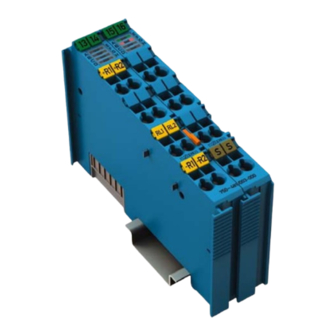
Page 16: View
750-481/003-000 2AI RTD Ex i s: 19 /Alle Serien (Allgemeine Module)/Überschriften für alle Serien/Ansicht - Überschrift 2 @ 4\mod_1240984217343_21.doc @ 31958 @ 2 @ 1 View Po s: 20 /Serie 750 (WAGO-I/O-SYSTEM)/Gerätebeschreibung/Ansicht/Analogeingangsklemmen/Ansicht 750-0481 @ 5\mod_1246000393593_21.doc @ 36136 @ @ 1 13 14 15 16... -
Page 17: Connectors
Do not place the I/O modules on the gold spring contacts in order to avoid soiling or scratching! s: 24.3 /Serie 750 (WAGO-I/O-SYSTEM)/Wichtige Erläuterungen/Sicherheitshinweise/Achtung/Achtung: ESD - Auf gute Erdung der Umgebung achten! @ 7\mod_1266318538667_21.doc @ 50708 @ @ 1 Ensure that the environment is well grounded! The modules are equipped with electronic components that may be destroyed by electrostatic discharge. -
Page 18: Power Contacts/Field Supply
Figure 4: Power jumper contacts Po s: 27.3 /Serie 750 (WAGO-I/O-SYSTEM)/Wichtige Erläuterungen/Sicherheitshinweise/Achtung/Achtung: Maximaler Strom Ex i Einspeisung 750-06xx 0,5 A / 1,0 A @ 7\mod_1274358256668_21.doc @ 56898 @ @ 1 Do not exceed maximum current via power contacts! The maximum current available from the 750-625 Ex-i Supply Module is 500 mA. -
Page 19: Cage Clamp Connections
WAGO-I/O-SYSTEM 750 Device Description 750-481/003-000 2AI RTD Ex i s: 29 /Serie 750 (WAGO-I/O-SYSTEM)/Gerätebeschreibung/Anschlüsse/CAGE CLAMP-Anschlüsse - Überschrift 3 @ 6\mod_1256296337770_21.doc @ 43674 @ 3 @ 1 ® 3.2.3 CAGE CLAMP Connections Po s: 30 /Serie 750 (WAGO-I/O-SYSTEM)/Gerätebeschreibung/Anschlüsse/Analogeingangsklemmen/Anschlüsse 750-0481 @ 5\mod_1246000467515_21.doc @ 36144 @ @ 1... -
Page 20: Display Elements
Po s: 34 /Alle Serien (Allgemeine Module)/Überschriften für alle Serien/Bedienelemente - Überschrift 2 @ 4\mod_1239191655456_21.doc @ 30439 @ 2 @ 1 Operating Elements Po s: 35 /Serie 750 (WAGO-I/O-SYSTEM)/Gerätebeschreibung/Bedienelemente/Bedienelemente Busklemme 750-xxxx nicht vorhanden @ 4\mod_1236322031125_21.doc @ 28063 @ @ 1 The I/O module 750-481/003-000 has no operating elements. -
Page 21: Schematic Diagram
37 /Alle Serien (Allgemeine Module)/Überschriften für alle Serien/Schematisches Schaltbild - Überschrift 2 @ 4\mod_1240984441312_21.doc @ 31967 @ 2 @ 1 Schematic Diagram Po s: 38 /Serie 750 (WAGO-I/O-SYSTEM)/Gerätebeschreibung/Schematische Schaltbilder/Analogeingangsklemmen/Schematisches Schaltbild 750-0481 @ 5\mod_1246000666921_21.doc @ 36168 @ @ 1 +R 1 / +R 2... -
Page 22: Technical Data
40 /Alle Serien (Allgemeine Module)/Überschriften für alle Serien/Technische Daten - Überschrift 2 @ 3\mod_1232967587687_21.doc @ 26924 @ 2 @ 1 Technical Data Po s: 41 /Serie 750 (WAGO-I/O-SYSTEM)/Gerätebeschreibung/Technische Daten/Analogeingangsklemmen/Technische Daten 750-0481 @ 5\mod_1245995330359_21.doc @ 36088 @ 33333 @ 1 3.6.1... -
Page 23: Inputs
Inputs Table 10: Technical Data Inputs Number of inputs Sensor types Resistance temperature: (setting over software WAGO-I/O- Pt 100 (factory preset), Pt 200, Pt 500, CHECK 2) Pt 1000, Ni 100, Ni 120, Ni 1000, Resistance measuring: 1.2 kΩ, 5 kΩ, Potentiometer: 1.2 kΩ... -
Page 24: Explosion Protection
Device Description WAGO-I/O-SYSTEM 750 750-481/003-000 2AI RTD Ex i 3.6.5 Explosion Protection Table 11: Technical Data Explosion Protection Ex directive 94/9/EG EN 60079-0:2006, EN 60079-11:2007, EN 60079-15:2005, EN 61241-0:2006, EN 61241-1:2004, EN61241-11:2006 Safety data = 7.2 V = 5.8 mA = 10.5 mW... -
Page 25: Approvals
Po s: 49 /Alle Serien (Allgemeine Module)/Überschriften für alle Serien/Normen und Richtlinien - Überschrift 2 @ 4\mod_1242804031875_21.doc @ 33646 @ 2 @ 1 Standards and Guidelines Po s: 50 /Serie 750 (WAGO-I/O-SYSTEM)/Gerätebeschreibung/Normen und Richtlinien/EMV-Normen Busklemme 750-xxxx, ohne Variantenangabe @ 4\mod_1242803944015_21.doc @ 33642 @ @ 1 750-481/003-000 I/O modules meet the following requirements on emission and immunity of interference: Po s: 51 /Alle Serien (Allgemeine Module)/Normen und Richtlinien/EG-EMV-Richtlinie 2004/108/EG @ 7\mod_1274262373820_21.doc @ 56628 @ @ 1... -
Page 26: Assembly
DI4. s: 56.4 /Serie 750 (WAGO-I/O-SYSTEM)/Wichtige Erläuterungen/Sicherheitshinweise/Achtung/Achtung: Aneinanderreihen von Busklemmen nur bei offener Nut! @ 6\mod_1256193351448_21.doc @ 43417 @ @ 1 Assemble the I/O modules in rows only if the grooves are open! Please take into consideration that some bus modules have no or only a few power jumper contacts. -
Page 27: Inserting And Removing Devices
56.7 /Serie 750 (WAGO-I/O-SYSTEM)/Montieren/Geräte einfügen und entfernen - Überschrift 2 @ 3\mod_1231768483250_21.doc @ 25950 @ 2 @ 1 Inserting and Removing Devices Po s: 56.8 /Serie 750 (WAGO-I/O-SYSTEM)/Wichtige Erläuterungen/Sicherheitshinweise/Gefahr/Gefahr: Vorsicht bei der Unterbrechung von FE! @ 6\mod_1256193919214_21.doc @ 43423 @ @ 1 Use caution when interrupting the PE! Make sure that people or equipment are not placed at risk when removing an I/O module and the associated PE interruption. -
Page 28: Removing The I/O Module
(if any) to the fieldbus coupler/controller or to the previous or possibly subsequent I/O module are established. Po s: 56.11 /Serie 750 (WAGO-I/O-SYSTEM)/Montieren/Busklemme entfernen @ 4\mod_1239169375203_21.doc @ 30334 @ 3 @ 1 4.2.2 Removing the I/O Module Remove the I/O module from the assembly by pulling the release tab. -
Page 29: Connect Devices
58 /Alle Serien (Allgemeine Module)/Überschriften für alle Serien/Geräte anschließen - Überschrift 1 @ 3\mod_1234172889468_21.doc @ 27460 @ 1 @ 1 Connect Devices Po s: 59 /Serie 750 (WAGO-I/O-SYSTEM)/Anschließen/Leiter an CAGE CLAMP anschließen - Überschrift 2 und Text @ 3\mod_1225448660171_21.doc @ 24928 @ 2 @ 1 ®... -
Page 30: Connection Examples
61 /Alle Serien (Allgemeine Module)/Überschriften für alle Serien/Anschlussbeispiele - Überschrift 2 @ 4\mod_1240996036328_21.doc @ 32010 @ 2 @ 1 Connection Examples Po s: 62 /Serie 750 (WAGO-I/O-SYSTEM)/Anschließen/Anschlussbeispiele/Analogeingangsklemmen/Anschlussbeispiele 750-0481 @ 5\mod_1247206698529_21.doc @ 37114 @ 3333 @ 1 5.2.1 2 x RTD, 2-Conductors... -
Page 31: Resistance
WAGO-I/O-SYSTEM 750 Connect Devices 750-481/003-000 2AI RTD Ex i 5.2.3 2 x Resistance +R1 +R2 RL1 RL2 -R1 -R2 750-481 / 003-000 Fig. 14: Example Connection 2 x Resistance 5.2.4 2 x Potentiometer +R1 +R2 RL1 RL2 -R1 -R2 750-481 / 003-000 Fig. -
Page 32: Process Image
Po s: 66 /Serie 750 (WAGO-I/O-SYSTEM)/Prozessabbild Klemmenbus/Hinweis: Statusbyte-Auswertung abhängig vom Feldbussystem @ 6\mod_1256127208766_21.doc @ 43344 @ @ 1 Evaluation of Status Byte Some fieldbus systems can process status information of process value by means of a status byte. -
Page 33: Table: 12 Process Image Configuration For Pt 100, Pt 200, Pt 500 And Pt 1000
WAGO-I/O-SYSTEM 750 Process Image 750-481/003-000 2AI RTD Ex i Table: 12 Process Image Configuration for Pt 100, Pt 200, Pt 500 and Pt 1000, with broken wire diagn. Status- Numercial value Temperature byte Error °C hex. AI 1, 2 binary hex. -
Page 34: Configuration For Ni Resistance Sensors
Process Image WAGO-I/O-SYSTEM 750 750-481/003-000 2AI RTD Ex i Configuration for Ni Resistance Sensors To evaluate the nickel resistance sensors, the measured values of the resistance are converted and sent as temperature values. All temperature values are represented in a standard numeric format. The possible numerical range matches the defined temperature range of the Ni sensors from -60 °C to +250 °C or from -... -
Page 35: Table: 14 Process Image Configuration For Ni 120, With Broken Wire Diagn
WAGO-I/O-SYSTEM 750 Process Image 750-481/003-000 2AI RTD Ex i Table: 14 Process Image Configuration for Ni 120, with broken wire diagn. Status- Numercial value Temperature byte Error °C hex. AI 1,2 binary hex. dec. <-80.0 '1000.0000.0000.0001' 0x8001 -32767 0x41 -80.0 '1111.1100.1110.0000'... -
Page 36: Configuration For Resistance Measuring
Process Image WAGO-I/O-SYSTEM 750 750-481/003-000 2AI RTD Ex i Configuration for Resistance Measuring Resistance measuring is only possible using 2-wire devices.The measured values are sent out directly when measuring the resistance. In the measuring range from 10 Ω to 1.2 kΩ, the resolution is 1 digit per 0.1 Ω. -
Page 37: Configuration For Potentiometer Measuring
WAGO-I/O-SYSTEM 750 Process Image 750-481/003-000 2AI RTD Ex i Configuration for Potentiometer Measuring Potentiometer measuring is only possible using 3-wire devices. When a potentiometer is used for measurement, the relative position of the connected potentiometer is expressed in percent: Slider x ... -
Page 38: Use In Hazardous Environments
69.1 /Alle Serien (Allgemeine Module)/Einsatz in Ex-Bereichen/Einsatz in explosionsgefährdeten Bereichen - Überschrift 1 @ 3\mod_1224075191281_21.doc @ 24084 @ 1 @ 1 Use in Hazardous Environments Po s: 69.2 /Serie 750 (WAGO-I/O-SYSTEM)/Einsatz in Ex-Bereichen/Einsatzbereich Serie 750 @ 3\mod_1234272230203_21.doc @ 27500 @ @ 1 The WAGO-I/O-SYSTEM 750 (electrical equipment) is designed for use in Zone 2 hazardous areas. -
Page 39: Identification
69.4 /Serie 750 (WAGO-I/O-SYSTEM)/Einsatz in Ex-Bereichen/Kennzeichnung - Überschrift 2 @ 3\mod_1224157499140_21.doc @ 24182 @ 2 @ 1 Identification Po s: 69.5 /Serie 750 (WAGO-I/O-SYSTEM)/Einsatz in Ex-Bereichen/Kennzeichnung für Europa gemäß CENELEC und IEC - Überschrift 3 @ 3\mod_1224157620203_21.doc @ 24185 @ 3 @ 1 7.1.1 For Europe according to CENELEC and IEC Po s: 69.6 /Serie 750 (WAGO-I/O-SYSTEM)/Einsatz in Ex-Bereichen/Bedruckung gemäß... -
Page 40: Figure 18: Example Of Side Marking Of Ex I And Iec Ex I Approved I/O Modules
750-481/003-000 2AI RTD Ex i s: 69.8 /Serie 750 (WAGO-I/O-SYSTEM)/Einsatz in Ex-Bereichen/Bedruckung gemäß Ex i und IEC Ex i @ 7\mod_1274338578856_21.doc @ 56679 @ @ 1 Figure 18: Example of side marking of Ex i and IEC Ex i approved I/O modules Figure 19: Inscription text detail acc. -
Page 41: Table 19: Description Of The Inscription
WAGO-I/O-SYSTEM 750 Use in Hazardous Environments 750-481/003-000 2AI RTD Ex i Table 19: Description of the inscription Inscription text Description TÜV 07 ATEX 554086 X Approving authority or TUN 09.0001X certificate numbers Dust Device group: All except mining 3(1)D Device category: Zone 22 device (Zone 20 subunit) -
Page 42: For America According To Nec 500
Use in Hazardous Environments WAGO-I/O-SYSTEM 750 750-481/003-000 2AI RTD Ex i s: 69.10 /Serie 750 (WAGO-I/O-SYSTEM)/Einsatz in Ex-Bereichen/Kennzeichnung für Amerika gemäß NEC - Überschrift 3 @ 3\mod_1224158423187_21.doc @ 24188 @ 3 @ 1 7.1.2 For America according to NEC 500 Po s: 69.11 /Serie 750 (WAGO-I/O-SYSTEM)/Einsatz in Ex-Bereichen/Bedruckung gemäß... -
Page 43: Installation Regulations
Po s: 69.16 /Dokumentation allgemein/Gliederungselemente/------Leerzeile------ @ 3\mod_1224662755687_0.doc @ 24460 @ @ 1 Po s: 69.17 /Dokumentation allgemein/Gliederungselemente/------Leerzeile------ @ 3\mod_1224662755687_0.doc @ 24460 @ @ 1 Po s: 69.18 /Serie 750 (WAGO-I/O-SYSTEM)/Einsatz in Ex-Bereichen/Achtung: Errichtungsbestimmungen Serie 750 beachten @ 3\mod_1224158893890_21.doc @ 24191 @ @ 1 Notice the following points... -
Page 44: Special Conditions For Safe Operation Of The Atex And Iec Ex (Acc. Demko 08 Atex 142851X And Iecex Ptb 07.0064)
WAGO-I/O-SYSTEM 750 750-481/003-000 2AI RTD Ex i s: 69.20 /Serie 750 (WAGO-I/O-SYSTEM)/Einsatz in Ex-Bereichen/Besondere Bedingungen für den sicheren ATEX- und IEC-Ex-Betrieb gem. DEMKO 08 ATEX 142851X & IECEx @ 7\mod_1274277358920_21.doc @ 56642 @ 3 @ 1 7.2.1 Special Conditions for Safe Operation of the ATEX and IEC Ex (acc. -
Page 45: Special Conditions For Safe Use (Atex Certificate Tüv 07 Atex 554086 X)
Use in Hazardous Environments 750-481/003-000 2AI RTD Ex i s: 69.22 /Serie 750 (WAGO-I/O-SYSTEM)/Einsatz in Ex-Bereichen/Besondere Bedingungen für den sicheren Ex-Betrieb gem. ATEX-Zertifikat TÜV 07 ATEX 554086 X @ 7\mod_1274277032671_21.doc @ 56636 @ 3 @ 1 7.2.2 Special conditions for safe use (ATEX Certificate TÜV 07... -
Page 46: Special Conditions For Safe Use (Iec-Ex Certificate Tun 09.0001
WAGO-I/O-SYSTEM 750 750-481/003-000 2AI RTD Ex i s: 69.24 /Serie 750 (WAGO-I/O-SYSTEM)/Einsatz in Ex-Bereichen/Besondere Bedingungen für den sicheren Ex-Betrieb gem. IEC-Ex-Zertifikat TUN 09.0001 X @ 7\mod_1274277251185_21.doc @ 56639 @ 3 @ 1 7.2.3 Special conditions for safe use (IEC-Ex Certificate TUN 09.0001 X) -
Page 47: Ansi/Isa 12.12.01
WAGO-I/O-SYSTEM 750 Use in Hazardous Environments 750-481/003-000 2AI RTD Ex i s: 69.26 /Serie 750 (WAGO-I/O-SYSTEM)/Einsatz in Ex-Bereichen/Errichtungsbestimmungen ANSI ISA 12.12.01 @ 3\mod_1224161936609_21.doc @ 24200 @ 3 @ 1 7.2.4 ANSI/ISA 12.12.01 This equipment is suitable for use in Class I, Division 2, Groups A, B, C, D or non-hazardous locations only. -
Page 48: List Of Figures
List of Figures WAGO-I/O-SYSTEM 750 750-481/003-000 2AI RTD Ex i Po s: 71 /Dokumentation allgemein/Verzeichnisse/Abbildungsverzeichnis - Überschrift 1 und Verzeichnis @ 3\mod_1219222916765_21.doc @ 21080 @ @ 1 List of Figures Figure 1: Supply Principle Ex i ................14 Fig. 2: View......................16 Figure 3: Data contacts.................. -
Page 49: List Of Tables
WAGO-I/O-SYSTEM 750 List of Tables 750-481/003-000 2AI RTD Ex i s: 73 /Dokumentation allgemein/Verzeichnisse/Tabellenverzeichnis - Überschrift 1 und Verzeichnis @ 3\mod_1219222958703_21.doc @ 21084 @ @ 1 List of Tables Table 1: Number Notation..................8 Table 2: Font Conventions ..................8 Table 3: Caption acc. - Page 50 Pos: 75 /Dokumentation allgemein/Einband/Einband Rückseite @ 9\mod_1285229376516_21.doc @ 64944 @ @ 1 WAGO Kontakttechnik GmbH & Co. KG Postfach 2880 • D-32385 Minden Hansastraße 27 • D-32423 Minden Phone: +49/5 71/8 87 – 0 Fax: +49/5 71/8 87 – 1 69 E-Mail: info@wago.com...
Need help?
Do you have a question about the WAGO-I/O-SYSTEM 750 750-481/003-000 and is the answer not in the manual?
Questions and answers