Table of Contents
Advertisement
Quick Links
Download this manual
See also:
System Description
Advertisement
Table of Contents

Related Manuals for Bosch Rexroth Rho 4.0


Summary of Contents for Bosch Rexroth Rho 4.0
- Page 1 Industrial Electric Drives Linear Motion and Service Mobile Hydraulics and Controls Assembly Technologies Pneumatics Automation Hydraulics Rexroth IndraControl VCP 20 Rexroth Rho 4.0 1070072365 Edition 04 Connectivity manual Project planning...
- Page 2 DOK-RHO*4*-RHO4.0*ANBE-PR04- 01.2005 Valid from VO08 EN-P E Bosch Rexroth AG, 1998 − 2005 Copyright Copying this document, giving it to others and the use or communication of the contents thereof without express authority, are forbidden. Offenders are liable for the payment of damages. All rights are reserved in the event of the grant of a patent or the registration of a utility model or design (DIN 34−1).
-
Page 3: Table Of Contents
1070072365 / 04 RhoMotion Electric Drives Bosch Rexroth AG and Controls Overview of all manuals Overview of all manuals Manual Contents System overview Connection conditions Rho 4.0 Connection conditions Rho 4.0 Installation Electrical connection Interfaces LED display Maintenance and replacement Order numbers System description Rho 4.0... - Page 4 Bosch Rexroth AG Electric Drives RhoMotion 1070072365 / 04 and Controls Overview of all manuals Manual Contents Software File management Scope of the rho4.1 Software Manual Contents Control functions Control functions Survey of special functions Accurate position switching Setting the machine position...
- Page 5 1070072365 / 04 RhoMotion Electric Drives Bosch Rexroth AG and Controls Overview of all manuals Manual Contents Measuring system parameters Belt parameters Drive parameters Servodyn-GC Drive parameter Servodyn-D Table of parameters Manual Contents BAPS3 Programming manual BAPS3 Programming manual Program structure...
- Page 6 Bosch Rexroth AG Electric Drives RhoMotion 1070072365 / 04 and Controls Overview of all manuals Manual Contents Function key assignment The marker box File ROPS4WIN.ini Selection of a file TCP/IP settings for ROPS4 Manual Contents DLL library DLL library Library functions Calling library functions in BAPS Block structure of the rho4.1...
- Page 7 1070072365 / 04 RhoMotion Electric Drives Bosch Rexroth AG and Controls Overview of all manuals Manual Contents DDE-Server DDE-Server Introduction Hardware and Software Operation Items of Server 4 Scope of function...
- Page 8 VIII Bosch Rexroth AG Electric Drives RhoMotion 1070072365 / 04 and Controls Overview of all manuals Notes:...
-
Page 9: System Overview
1070072365 / 04 RhoMotion Electric Drives Bosch Rexroth AG and Controls Contents Contents Page Safety Instructions ..... . . 1−1 Intended use . - Page 10 Bosch Rexroth AG Electric Drives RhoMotion 1070072365 / 04 and Controls Contents X21 and X22 Digital In (24 V) ......
-
Page 11: Installation
1070072365 / 04 RhoMotion Electric Drives Bosch Rexroth AG 1−1 and Controls Safety Instructions Safety Instructions Please read this manual before you startup the rho4. Store this manual in a place to which all users have access at any time. - Page 12 1−2 Bosch Rexroth AG Electric Drives RhoMotion 1070072365 / 04 and Controls Safety Instructions Qualified personnel The requirements as to qualified personnel depend on the qualification profiles described by ZVEI (central association of the electrical industry) and VDMA (association of German machine and plant builders) in:...
- Page 13 1070072365 / 04 RhoMotion Electric Drives Bosch Rexroth AG 1−3 and Controls Safety Instructions Safety markings on products Warning of dangerous electrical voltage! Warning of danger caused by batteries! Electrostatically sensitive components! Warning of hazardous light emissions (optical fiber cable emissions)!
- Page 14 1−4 Bosch Rexroth AG Electric Drives RhoMotion 1070072365 / 04 and Controls Safety Instructions Safety instructions in this manual DANGEROUS ELECTRICAL VOLTAGE This symbol is used to warn of a dangerous electrical voltage. The failure to observe the instructions in this manual in whole or in part may result in personal injury.
- Page 15 1070072365 / 04 RhoMotion Electric Drives Bosch Rexroth AG 1−5 and Controls Safety Instructions Safety instructions for the described product DANGER Danger of life through inadequate EMERGENCY-STOP devices! EMERGENCY-STOP devices must be active and within reach in all system modes. Releasing an EMERGENCY-STOP device must not...
- Page 16 1−6 Bosch Rexroth AG Electric Drives RhoMotion 1070072365 / 04 and Controls Safety Instructions CAUTION Danger to the module! Do not insert or remove the module while the controller is switched ON! This may destroy the module. Prior to inserting or...
-
Page 17: Documentation, Software Release And Trademarks
1070072365 / 04 RhoMotion Electric Drives Bosch Rexroth AG 1−7 and Controls Safety Instructions Documentation, software release and trademarks Documentation The present manual provides the user with comprehensive information about technical data, operation and configuration of the rho4.0. Overview of available documentation Part no. - Page 18 1−8 Bosch Rexroth AG Electric Drives RhoMotion 1070072365 / 04 and Controls Safety Instructions Release This manual refers to the following versions: Hardware version: rho4 Software release: ROPS4 Trademarks All trademarks of software installed on Rexroth products upon delivery are the property of the respective manufacturer.
-
Page 19: System Overview
8 axes and 8 kinematics can be controlled in the basis function scope. The rho4.0 is composed of a power supply unit, a carrier board, a PC board and a PCI plug point in which one of the 3 BOSCH field bus cards (CAN, INTERBUS-S and PROFIBUS-DP) can be operated. - Page 20 2−2 Bosch Rexroth AG Electric Drives RhoMotion 1070072365 / 04 and Controls System Overview There are 2 types of housing: one in the form of a drive module and one as 19” rack. The drive housing is located vertically near a drive module. The 19” hou- sing is 44mm high and is located horizontally in a 19”...
- Page 21 1070072365 / 04 RhoMotion Electric Drives Bosch Rexroth AG 2−3 and Controls System Overview Drive housing 19”-housing Á Á Á Á Á Á Á Á Á Á Á Á Á Á Á Á Á Á Á Á Á Á Á...
-
Page 22: Modular Mimic Display
2−4 Bosch Rexroth AG Electric Drives RhoMotion 1070072365 / 04 and Controls System Overview Modular mimic display Power supply 5V− CLOCK 24V −> 5V/ 5A Pentium 266MHz , resp. >3,3 >3,3V 400MHz 12V/1A −12V/150mA Host Bus 512K SRAM DRAM 64 MB... -
Page 23: Versions
The SRAM is reduced to 2 MB and only 2 CAN interfaces are availa- ble. By using a BOSCH field bus card in the PCI slot, the following other va- riants result: D rho4.0 L(R) with PCI_BM-DP in the 19” housing D rho4.0 L(R) with PCI_BM-DP in the drive housing... -
Page 24: Specifications
2−6 Bosch Rexroth AG Electric Drives RhoMotion 1070072365 / 04 and Controls System Overview Specifications Technical data housing Design as drive module or 19” mo- dule 44 mm high, aerated location D vertically near a drive module D horizontally in the 19” cabinet Pentium-Prozessor 266-, resp. -
Page 25: Operating Conditions
1070072365 / 04 RhoMotion Electric Drives Bosch Rexroth AG 2−7 and Controls System Overview Technical data Potential-free Ready contact 2-channel, triggered through: D power supply monitoring D Watchdog D Temperature monitoring Setting DIP-switch for component number (LAN-Addressing), without function at present, resp. for service purpo- Temperatur e operation ambient temperature 5 to 55 °C,... -
Page 26: Standards Compatibility
2−8 Bosch Rexroth AG Electric Drives RhoMotion 1070072365 / 04 and Controls System Overview Humidity Humidity class RH-2 acc. to DIN EN 61131-2, thawing not authorized. Air pressure In operation up to 2000 m above mean sea level acc. to... - Page 27 1070072365 / 04 RhoMotion Electric Drives Bosch Rexroth AG 2−9 and Controls System Overview As shipped from the factory, the rho4.0 comply with the require- ments for the CE mark of conformity. However, installing additional expansion cards will require a sup-...
- Page 28 2−10 Bosch Rexroth AG Electric Drives RhoMotion 1070072365 / 04 and Controls System Overview Notizen:...
-
Page 29: Installation
Bosch Rexroth AG 3−1 and Controls Installation Installation When installing the Bosch rho4.0, refer to the information on standards compatibility and operating conditions in sections 2.4 and 2.5. Installed positions and clearances Housing 19”-housing (horizontal) or drive housing (vertical) Weight approx. -
Page 30: Dimension Diagram 19" Housing
3−2 Bosch Rexroth AG Electric Drives RhoMotion 1070072365 / 04 and Controls Installation Dimension diagram 19” housing 482.6 (=19”) 462,4 Á Á Á Á Á Á Á Á Á Á Á Á mounting bore hole 29,5 403,6... -
Page 31: Dimension Diagram 19" Housing With Extended Remanence
1070072365 / 04 RhoMotion Electric Drives Bosch Rexroth AG 3−3 and Controls Installation Dimension diagram 19” housing with extended remanence (LR) 482,6 465,9 40,1 31,2 400,2 51,2... -
Page 32: Dimension Diagram Drive Housing
3−4 Bosch Rexroth AG Electric Drives RhoMotion 1070072365 / 04 and Controls Installation Dimension diagram drive housing 267,1 250,2 Á Á Á Á Á Á Á Á Á Á Á 43,6... -
Page 33: Electrical Connections
1070072365 / 04 RhoMotion Electric Drives Bosch Rexroth AG 4−1 and Controls Electrical Connections Electrical Connections Please note that, with respect to all electrical connections, the terminal connection plans and work instructions provided by the machine manu- facturer shall always be binding! -
Page 34: Protective Earth (Pe) Conductor & Screening Information . 4−2
4−2 Bosch Rexroth AG Electric Drives RhoMotion 1070072365 / 04 and Controls Electrical Connections Protective Earth (PE) conductor & screening information DANGER Dangerous conditions, functional failures and equipment da- mage on machine plant caused by substandard potential equalization or screening properties between system compo-... -
Page 35: Interference Suppression Information
1070072365 / 04 RhoMotion Electric Drives Bosch Rexroth AG 4−3 and Controls Electrical Connections Interference suppression information When designing the machine plant, observe and comply with governing regulations and statutory law with regard to interference suppression on individual components. This will increase the operational safety of the entire system. - Page 36 4−4 Bosch Rexroth AG Electric Drives RhoMotion 1070072365 / 04 and Controls Electrical Connections Mains Interference suppression examples Suppression of contacts (Alternating current, direct current, offset DC current) to b) For sensitive contacts, residual current when contact open! to c)
- Page 37 1070072365 / 04 RhoMotion Electric Drives Bosch Rexroth AG 4−5 and Controls Electrical Connections Suppression example − mains input:...
-
Page 38: Vdc Power Connection
4−6 Bosch Rexroth AG Electric Drives RhoMotion 1070072365 / 04 and Controls Electrical Connections 24 VDC power connection 24 VDC power connection At the X10 plug, the 24 Volt industrial voltage is fed, filtered and applied to the power supply unit. - Page 39 1070072365 / 04 RhoMotion Electric Drives Bosch Rexroth AG 4−7 and Controls Electrical Connections Safety transformer, as per EN 60742: 400V +5% 400V 400V −5% +24V Offset AC components of the type produced by an unregulated rotary current bridge circuit without smoothing, with a ripple factor of 5% (refer to DIN 40110/10.75, section 1.2), are permissible.
- Page 40 4−8 Bosch Rexroth AG Electric Drives RhoMotion 1070072365 / 04 and Controls Electrical Connections (green/yellow) Power supply W/ safety transformer as per EN 60742 24 V Cross-sections dependent on current draw, but MIN of 4 . For higher (blue) current draw, use 2 x 4 Max.
-
Page 41: Power Connections
1070072365 / 04 RhoMotion Electric Drives Bosch Rexroth AG 4−9 and Controls Electrical Connections 4.3.1 Power connections All system voltages have potential reference under each other and are connected to a place with housing potential. system voltages voltage max. cur- tolerance Undervolt. -
Page 42: Monitoring Of The Temperature And The Cpu Ventilator
4−10 Bosch Rexroth AG Electric Drives RhoMotion 1070072365 / 04 and Controls Electrical Connections Monitoring of the temperature and the CPU ventilator The temperature of the power supply unit is monitored. When the am- bient temperature of 58 °C is exceeded, a pre-warning appears. When the rho4.0 software recognizes this warning, the rho4.0 is shut down, the... -
Page 43: Interface Ports & Connectors 5−1
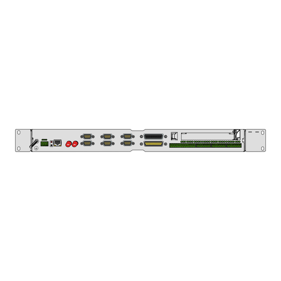
1070072365 / 04 RhoMotion Electric Drives Bosch Rexroth AG 5−1 and Controls Interface Ports & Connectors Interface Ports & Connectors Overview The following table specifies the installed IPC connector types, as well as their mating connectors. Designation at the hou-... - Page 44 5−2 Bosch Rexroth AG Electric Drives RhoMotion 1070072365 / 04 and Controls Interface Ports & Connectors Port and connector panel layout On the front panel, there are all interfaces accessible to the outside. All interfaces are marked. V24_3/X33 PCI-Slot A1...
-
Page 45: V24_1/X33 Through V24_3/X33 Serial Pc Ports
1070072365 / 04 RhoMotion Electric Drives Bosch Rexroth AG 5−3 and Controls Interface Ports & Connectors V24_1/X33 through V24_3/X33 serial PC ports 5.2.1 Pin assignment CAUTION Functional failures caused by poor shielding! Use only metallic or conductive connector/coupling shells providing large-area shield contact. - Page 46 5−4 Bosch Rexroth AG Electric Drives RhoMotion 1070072365 / 04 and Controls Interface Ports & Connectors Signal Ground Data Set Ready; receiving line, on which the con- nected peripheral device informs the rho4.0 that it is switched on and initialized.
- Page 47 1070072365 / 04 RhoMotion Electric Drives Bosch Rexroth AG 5−5 and Controls Interface Ports & Connectors Assignment as RS-232: DTR20-mA-Signal (Pin1) statical 20-mA source V24-RTS-Signal always active (statically on high); therefore (Pin7) an operation is also possible with a participant requiring hardware control (DSR inquired) Transmit Data;...
- Page 48 5−6 Bosch Rexroth AG Electric Drives RhoMotion 1070072365 / 04 and Controls Interface Ports & Connectors Floppy interface The external floppy drive 1070 085 274 can be connected to the 25-Pin- Floppy interface. It consists of a 1 m lang cable, a 1.44 Mb 31/2” floppy drive and an installation frame.
- Page 49 1070072365 / 04 RhoMotion Electric Drives Bosch Rexroth AG 5−7 and Controls Interface Ports & Connectors X34 PHG2000 CAUTION The connection of a rho4.1 floppy at this interface leads to the destruction of the floppy and the interface. The PHG2000 interface lays on a 25-pin DSUB socket. If the permanent load of EMERGENCY STOP and confirmation key is <...
- Page 50 5−8 Bosch Rexroth AG Electric Drives RhoMotion 1070072365 / 04 and Controls Interface Ports & Connectors X34 / rh4.0 Male connector Female connector Sub−D 25 pin Sub−D 25 pin Cable 0,19 wh 0,19 br 0,19 gn PGND 0,19 bl PGND...
- Page 51 1070072365 / 04 RhoMotion Electric Drives Bosch Rexroth AG 5−9 and Controls Interface Ports & Connectors 5.4.1 X10s safety relevant signals and 24-V power supply for digital outputs and PHG X10s Real time interface Connection for READY contacts, Emergency-stop contacts and confir- mation keys and feeding the 24V power supply for digital outputs and PHG.
-
Page 52: Ethernet-Interface
5−10 Bosch Rexroth AG Electric Drives RhoMotion 1070072365 / 04 and Controls Interface Ports & Connectors D The temperature of the rho4.0 rises beyond the permissible limit. D The Ready Watchdog has run out. D The RESET key has been actuated. -
Page 53: Ethernet (Mac)- And Ip Address
1070072365 / 04 RhoMotion Electric Drives Bosch Rexroth AG 5−11 and Controls Interface Ports & Connectors The metallic housing of the 100BaseT socket is set above the front shield on the control housing resp. the shield. The cable shield is set above the connector housing on the socket shield. -
Page 54: Sercos Interface
5−12 Bosch Rexroth AG Electric Drives RhoMotion 1070072365 / 04 and Controls Interface Ports & Connectors Fixed part: Manufacturer code, identifies clearly the type of the ethernet card and its manufacturer Components with specific part: is defined by the manufacturer The ethernet address cannot be modified by the customer. -
Page 55: X51, X52, X53 Can-Drives, Can-Transmitter, Sr-Can-Module
1070072365 / 04 RhoMotion Electric Drives Bosch Rexroth AG 5−13 and Controls Interface Ports & Connectors X51, X52, X53 CAN-drives, CAN-transmitter, SR-CAN-module, CAN-user-I/O Three Full CAN Controllers of type 82527 (Intel) are integrated, which are operated with a 16-MHz clock. -
Page 56: Connection Examples For The Can Interfaces
5−14 Bosch Rexroth AG Electric Drives RhoMotion 1070072365 / 04 and Controls Interface Ports & Connectors 5.7.1 Connection examples for the CAN interfaces rho4.0 as CAN-intermediate device Connector housing CAN_Shield CAN_H CAN_H_RES 120 R CAN_L Two cables, without bus connection Connect at the plug the incoming and outgoing CAN cable respectively to pin 2 and 7. - Page 57 1070072365 / 04 RhoMotion Electric Drives Bosch Rexroth AG 5−15 and Controls Interface Ports & Connectors Connect shield of the cable to the metallic connector housing. It is possible to interconnect 2 or 3 CAN interfaces and operate them at the same CAN bus. It must be ensured that the bus connec- tion is activated only at the last participant.
-
Page 58: X11 Digital Out (24
5−16 Bosch Rexroth AG Electric Drives RhoMotion 1070072365 / 04 and Controls Interface Ports & Connectors Working range of the digital inputs: limit value 0-state transition range 1-state UL/V IL/mA UT/V IT/mA UH/V IH/mA Max. Min. −3 max. 100 µs... -
Page 59: Pci-Slot A1
5.10 PCI-Slot A1 The PCI-Slot A1 corresponds to a 32-Bit-PCI-bus Slot in a PC. One of the BOSCH field bus cards (CAN, INTERBUS-S and PROFIBUS-DP) can be plugged in it. At the PCI-Slot, the following voltages are available: D +5 V up to max. - Page 60 5−18 Bosch Rexroth AG Electric Drives RhoMotion 1070072365 / 04 and Controls Interface Ports & Connectors 5.11 Expansion Card Interfaces 5.11.1 PCI_BM-xxx Card This busmaster expansion card is the interface of the software PLC. The PLC signals are transmitted over the integrated system bus.
- Page 61 1070072365 / 04 RhoMotion Electric Drives Bosch Rexroth AG 5−19 and Controls Interface Ports & Connectors Interbus S ”PCI_BM-IBS” Female DB-9 Type InterBus-S Remote (as per EN 50178) X71 InterBus-S InterBus-S GND ISO +5V ISO − Screen applied to metal shell of...
- Page 62 5−20 Bosch Rexroth AG Electric Drives RhoMotion 1070072365 / 04 and Controls Interface Ports & Connectors PROFIBUS DP ”PCI_BM-DP” Female DB-9 Max. cable length 500 kbit/s 400 m depending on baud rate 1500 kbit/s 200 m (as per DIN EN 19245 Part...
- Page 63 1070072365 / 04 RhoMotion Electric Drives Bosch Rexroth AG 5−21 and Controls Interface Ports & Connectors 5.11.2 PCI_CAN Card This interface is a second CAN bus for fast transmission of measured data to the PC. CAN bus Male DB-9 connector...
- Page 64 5−22 Bosch Rexroth AG Electric Drives RhoMotion 1070072365 / 04 and Controls Interface Ports & Connectors Notes:...
-
Page 65: Led Display
1070072365 / 04 RhoMotion Electric Drives Bosch Rexroth AG 6−1 and Controls LED Display LED Display The rho4.0 has LEDs to display the current states. H30-37 H10-H17 Á Á Á Á Á Á Á Á Á Á Á Key RES... - Page 66 6−2 Bosch Rexroth AG Electric Drives RhoMotion 1070072365 / 04 and Controls LED Display Status LEDs The status LEDs monitor the 24-V power supply and the internal fuse for the digital outputs and the PHG. When the power supply of the rho4.0 is switched off, the LEDs H2 to H4 and H41 to H47 turn off, H1 remains permanently on.
- Page 67 1070072365 / 04 RhoMotion Electric Drives Bosch Rexroth AG 6−3 and Controls LED Display H 43 rho4.0 Startup: D at startup, the CPU fan does not LED flashes for 3 s, then run or there is a temperature war- the rho4.0 switches off...
- Page 68 6−4 Bosch Rexroth AG Electric Drives RhoMotion 1070072365 / 04 and Controls LED Display rho4.0 has been shut down through temperature warning: D H40 is permanently on (24-V power supply for digital outputs and PHG are present) D H41 off...
- Page 69 1070072365 / 04 RhoMotion Electric Drives Bosch Rexroth AG 6−5 and Controls LED Display rho4.0 has been shut down through ’CPU fan is not running’: D H40 is permanently on (24-V-power supply for digital outputs and PHG are present) D H41 off...
- Page 70 6−6 Bosch Rexroth AG Electric Drives RhoMotion 1070072365 / 04 and Controls LED Display Designation Function Reset and restart of the rho4.0 Key on the front screen Switch S201 Component number 8-DIP switch for the set- (placed below the ting of the compontent case−ventilator)
-
Page 71: Maintenance And Replacement
1070072365 / 04 RhoMotion Electric Drives Bosch Rexroth AG 7−1 and Controls Maintenance and Replacement Maintenance and Replacement The rho4.0 is maintenance-free. It is however possible that the CF card and the battery must be changed. Maintenance schedule Include in your maintenance plan the following activites: D Check all plug-type connections and terminal connections of the components at least once a year for correct fixture and damage. -
Page 72: Battery
7−2 Bosch Rexroth AG Electric Drives RhoMotion 1070072365 / 04 and Controls Maintenance and Replacement Battery The installed battery buffers the SRAM components and the RTC on the ETX board when the 24-V power supply unit is not switched on. - Page 73 1070072365 / 04 RhoMotion Electric Drives Bosch Rexroth AG 7−3 and Controls Maintenance and Replacement Since the experience has shown that the components only draw a frac- tion of the given buffer current and when the device is switched off (as in the buffer case) there is only a temperature of 30 to 45 °C inside the de-...
- Page 74 7−4 Bosch Rexroth AG Electric Drives RhoMotion 1070072365 / 04 and Controls Maintenance and Replacement Notes:...
-
Page 75: Accessories
1070072365 / 04 RhoMotion Electric Drives Bosch Rexroth AG 8−1 and Controls Order numbers Order numbers Order numbers of the variants of the basic device and additional soft- ware functions, see price list rho3, rho4 (1070 073 902, German). Accessories Designation Order no. -
Page 76: Spare Parts
8−2 Bosch Rexroth AG Electric Drives RhoMotion 1070072365 / 04 and Controls Order numbers Premanufactured fibre optic cable, male connectors on both sides : Length Designation Order no. 23 cm DM 4A bis DM 85B 1070 917 886 (without strain relief) -
Page 77: A Appendix
1070072365 / 04 RhoMotion Electric Drives Bosch Rexroth AG A−1 and Controls Appendix Appendix Abbreviations Abbreviation Meaning BAPS3 Movement and sequence program- ming language, version 3 Drive designation, here drive C (hard disk drive) Controller Area Network Dynamic Data Exchange... -
Page 78: Index
A−2 Bosch Rexroth AG Electric Drives RhoMotion 1070072365 / 04 and Controls Appendix Index Interfaces ambient temperature, 2−7 CAN bus, 5−21 Expansion Cards, 5−18 Floppy, 5−6 Battery, 7−2 X35 PHG2000, 5−7 Buffer time, 7−2 Interference suppression implementation, 4−3 information, 4−3 CAN bus, 5−21... -
Page 79: System Overview
1070072365 / 04 RhoMotion Electric Drives Bosch Rexroth AG A−3 and Controls Appendix ROPS4 coupling, 5−5 Safety instructions, 1−4 Safety markings, 1−3 safety transformer, 4−7 Screening, information, 4−2 Spare parts, 1−6 spark quenching circuit, 4−3 Specifications, 2−6 Standard operation, 1−1 standards compatibility, 2−8... - Page 80 A−4 Bosch Rexroth AG Electric Drives RhoMotion 1070072365 / 04 and Controls Appendix Notes:...
- Page 81 Bosch Rexroth AG Electric Drives and Controls P.O. Box 13 57 97803 Lohr, Germany Bgm.-Dr.-Nebel-Str. 2 97816 Lohr, Germany Phone +49 (0)93 52-40-50 60 +49 (0)93 52-40-49 41 service.svc@boschrexroth.de www.boschrexroth.com Printed in Germany 1070072365 DOK-RHO*4*-RHO4.0*ANBE-PR04-EN-P...
Need help?
Do you have a question about the Rexroth Rho 4.0 and is the answer not in the manual?
Questions and answers