Labom CI4 Series Operating Instructions Manual
Level transmitter pascal ci4 level
Hide thumbs
Also See for CI4 Series:
- Sil instructions (4 pages) ,
- Manual (28 pages) ,
- Operating instructions manual (24 pages)
Table of Contents
Advertisement
Quick Links
Level transmitter PASCAL Ci4 LEVEL
Type series CI4xxx
Operating Instructions
1 General Information....................................................................................................... 2
1.1 General Safety Notes .............................................................................................. 2
1.2 Intended Use ........................................................................................................... 2
1.3 Conformity with EU Regulations .............................................................................. 2
1.4 ATEX Approval ........................................................................................................ 2
2 Transportation and Storage .......................................................................................... 2
3 Installation and Commissioning .................................................................................. 2
3.1 Mechanical Installation ............................................................................................ 3
3.2 Electrical Connection .............................................................................................. 3
3.3 Devices with Diaphragm Seal ................................................................................. 4
3.4 Mounting the Remote Display ................................................................................. 4
4 Operation ........................................................................................................................ 5
4.1 Test Terminals ........................................................................................................ 5
4.2 Remove Display / Activate Write Protection ............................................................ 6
4.3 Maintenance / Service ............................................................................................. 6
5 Disassembly ................................................................................................................... 7
6 User Manual ................................................................................................................... 8
6.1 Principles of the parameterisation concept.............................................................. 8
6.2 Basics of the Operating Concept ........................................................................... 11
6.3 Display Mode / Measured Value Display ............................................................... 12
6.4 Menue Mode / Operating Menue ........................................................................... 15
6.5 The Menue Tree .................................................................................................... 18
Questions about this device? Hotline +49 (0) 4408 804 - 444
LABOM Mess- und Regeltechnik GmbH Im Gewerbepark 13 27798 Hude Deutschland
Tel.: +49 (0) 4408 804-0 Fax: +49 (0) 4408 804-100 e-mail: info@labom.com www.labom.com
BA_078
Rev 1F6
Page 1/36
Advertisement
Table of Contents

Related Manuals for Labom CI4 Series


Summary of Contents for Labom CI4 Series
-
Page 1: Table Of Contents
BA_078 Questions about this device? Hotline +49 (0) 4408 804 - 444 Rev 1F6 LABOM Mess- und Regeltechnik GmbH Im Gewerbepark 13 27798 Hude Deutschland Page 1/36 Tel.: +49 (0) 4408 804-0 Fax: +49 (0) 4408 804-100 e-mail: info@labom.com www.labom.com... -
Page 2: General Information
In addition to this instruction, be sure to observe all statutory requirements, appli- cable standards, the additional technical specifications on the accompanying data sheet (see www.labom.com) as well as the specifications indicated on the type plate. General Safety Notes The installation, set up, service or disassembly of this device must only be done by trained, qualified personnel using suitable equipment and authorized to do so. -
Page 3: Mechanical Installation
Mechanical Installation Use gaskets, if required, that are suitable for the process connection and resistant to the media. Before starting operation, check the process connection carefully for leaks under pressure. You can use the device in any mounting position. Normally the transmitter is adjusted for a vertical mounting position. -
Page 4: Devices With Diaphragm Seal
The back plate of the housing is universally suitable for wall mounting or pipe mounting for pipe diameters from 30 – 64 mm. For pipe mounting, you can order the corresponding U-bolts from LABOM. For best EMC protection, only use the included cable. -
Page 5: Operation
This modification can be performed during operation. We do recommend, however, to switch off the device during the modification. Figure 3: Remote display and control unit after installation Operation During operation, take care that the device remains within its intended pressure and tem- perature ranges. -
Page 6: Remove Display / Activate Write Protection
Remove Display / Activate Write Protection Using the DIP switch in the device, you can disable changes to the configuration via the display or via HART (not for type series CI4xx3 with a process connection on the back). To activate the write protection, you must first remove the display module. Proceed as fol- lows: −... -
Page 7: Disassembly
Disassembly When measuring hot media, make sure that the device has cooled down prior to any dis- mounting or wear appropriate protective clothing to avoid burns. Switch off the power supply to the device before disconnecting the electrical connections. Once this is done, the device may be mechanically removed. Warning Opening pressurized lines might cause severe injuries. -
Page 8: User Manual
User Manual The device can be configured via the display module as well as the HART protocol. The following pages describe operation and configuration of the device using the display mod- ule. (valid from display module software version 2.0.0). An overview of the menue structure can be found on the last page of this document. Principles of the parameterisation concept Basic requirement for correct level measurements are correct pressure measurements. - Page 9 6.1.2 Tank shape The fill height is converted to a fill volume fill height using the tank shape table. The table is stored in the device as a series of fill height/fill volume pairs. The tank shape table can therefore be easily deter- mined from the tank documentation.
- Page 10 6.1.4 Calculating the fill weight If a fill volume is available, the device calcu- fill volume lates the fill weight from it using the density. The fill volume and weight are proportional ∙ to each other. The level zero is also the reference point for fill weight the fill weight.
-
Page 11: Basics Of The Operating Concept
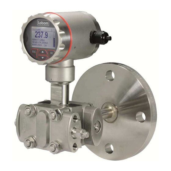
Basics of the Operating Concept The display module consists of a dot-matrix display with 80x120 pixels as well as a 4-button control panel. The four buttons below the display allow an intuitive operation of the device. The gen- Figure 12: Control elements eral functionality of the buttons is identical in all operating modes. -
Page 12: Display Mode / Measured Value Display
− Header: Icon description, if applicable. Otherwise "Value" − Data area: Measured values and parameters according to the selected display mode (see 6.3.4) Display of device data (see 6.3.1) − Header: Title for the displayed device data − Data area: Device data Operating menue −... - Page 13 − HART data (address, tag, descriptor, date) − Device identification (device ID, order number, serial number) − Module information (hardware and software versions, serial numbers) 6.3.2 Locking the Menue You can lock the menue with a key combination at the device. Press and hold the ESC- key and press then OK to activate the menue lock.
- Page 14 6.3.4 Display layouts You can configure the layout of the measured value display as well as the displayed infor- mation individually. There are seven different layouts available: Designation Layout Description Example Fill level 4 Three secondary values are displayed 1st value values under the main value.
-
Page 15: Menue Mode / Operating Menue
For all further values, you can additionally choose from the following data: − Sensor temperature − ATC temperature (for devices including the ATC option) − Density − Device ID (see 6.5.10.1) − HART tag − HART descriptor When information (such as the device ID) cannot be displayed in a short layout placehold- er, "###"... - Page 16 Button Function Scroll up in the menue, increase value/position in list Scroll down in the menue, decrease value/position in list Select menue, confirm value/list entry Cancel the data entry or menue selection, return to the next higher menue ESC long Cancel menue mode, return to display mode Table 5: Button functions in the operating menue 6.4.1...
- Page 17 6.4.2 Setting a numeric value When setting numeric values, the screen shows the following elements (from top to bot- tom): − Designation of the parameter that can be set − Help text (if applicable) − Numeric value and unit − Function of buttons −...
-
Page 18: The Menue Tree
Figure 17: Procedure for setting a numeric value (e.g. from 1.0 to 0.9) The Menue Tree In the following, the display and adjustment options are described by their position in the menue tree. An overview of the menue tree can be found on the last page of this docu- ment. - Page 19 6.5.2 „Quick Setup“ menue In Quick Setup, basic configuration options are combined to make it possible to quickly configure key functions. All functions of the quick setup can also be found at another posi- tion in the menue tree. The following functions are available in the Quick Setup menue: Menue entry Description Sprache/Language...
- Page 20 6.5.3.1 Level wizard The fill level wizard allows the easy parameterisation of the device. You are guided through all the necessary setting dialogue boxes. START unit density Enter density density unit height Enter height offset (defining the level zero) height offset select measurand Select measurand for...
- Page 21 Teaching-in the density You can also teach-in the density on the tank. A basic requirement is that the height offset is correctly set and Input of current fill height the fill height (relative to the level ze- based on level zero ro) can be determined with sufficient accuracy.
- Page 22 6.5.3.4 "Tank shape" submenue Parameterise and manage the tank shape table that is used to calculate the volume from the fill height in the "Tank shape" submenue. The tank shape pairs serve as control points of a tank shape curve. The volume is interpo- lated linearly between the tank shape pairs.
- Page 23 Switching the tank shape on/off The tank shape can not be edited and used for the volume calculation at the same time. It must be switched off before changing or teaching in the tank shape. The set alarm current is then issued at the current output if the volume or weight is selected as the measurand. The following steps are performed when switching on the tank shape: −...
- Page 24 height volume height volume height volume (measured) (entered) (sorted) (shifted) -3,6 m 4,1 m -2 m -3 m 0,6 m 2,2 m 0,8 m 0,8 m -3 m -2 m 1,6 m 0,8 m 2,2 m 2,2 m -3,6 m 3,6 m 4,1 m 4,1 m...
- Page 25 6.5.4.3 Upper and lower adjustment The lower adjustment results in an offset of the characteristic curve. It thus affects zero and span of the measuring range. The upper adjustment changes the slope of the characteristic curve by correcting the span of the measuring range.
- Page 26 6.5.5 "Display" menue In the "Display" menue, you find all the settings that affect the display on the screen. Menue entry Description Language Select menue language Units Setting units for the different measured and displayed values Display mode Configuration of the display layout and content (see 6.3.4) Decimal point Select setting of decimal point to determine number of decimal places...
- Page 27 Volume unit The unit in which the measured volume should be displayed and entered in the tank shape table can be selected from the following list: Unit Description Cubic metre (1 m = 10 = 10 = 1000 l) Litre (1 l = 1000 cm = 0,001 m Hectolitre (1 hl = 100 l = 0,1 m Cubic inch (1 in...
- Page 28 Unit Pressure The unit in which the measured pressure is to be shown can be selected from the following list: Unit Description mbar Millibar (1 mbar = 0,001 bar) Bar (1 bar = 1000 mbar = 10 Pascal (1 Pa = 1 kg/(m*s ) = 10 bar = 0,01 mbar) Hectopascal (1 hPa = 100 Pa = 1 mbar)
- Page 29 6.5.5.2 “Display mode” submenue In the "Display mode" submenue, you configure the representation of the measured values and additional information on the display. With the menue item “Screen layout” you configure the information that is displayed and its layout. Up to five values can be displayed at the same time. In the additional menue en- tries "1st value"...
- Page 30 6.5.6.1 Setting the damping Using an adjustable damping you can eliminate fast pressure changes or peaks from hav- ing direct influence to the output signal. The set value in seconds corresponds to the time constant of an exponential rise. After a sudden pressure change, it takes the damping time to reach 63.2% of the actual pressure at the output.
- Page 31 6.5.7 "Diagnosis" menue In this menue you can view and configure various diagnostic information. The following diagnostic functions are available: Menue entry Description Counter Display of operating hour counter and maintenance timer Min/max values Displaying and resetting the min/max values for the different measured variables Last error Display and reset of the last critical error...
- Page 32 6.5.8 „Simulation“ menue The different measurands and the current can be simulated in the "Simulation" menue to check the subsequent processing of measured values. The current simulation only affects the current output. The measurand simulations take all settings into account, i.e. including the damping and active tank shape if necessary. If the simulated variable has no effect on the current output, the measured value of the selected variable continues to be issued at the current output.
- Page 33 6.5.10.1 Device ID Using the device ID, you can show a custom text in the display if you configure the display mode accordingly (see 6.3.4). For instance, you can show the tag number continuously in the display. The device ID can be up to 16 characters long and consist of numbers, empty spaces, capital letters and special characters.
- Page 34 BA_078 Rev 1F6 Level transmitter PASCAL Ci4 LEVEL Page 34/36...
- Page 35 BA_078 Rev 1F6 Level transmitter PASCAL Ci4 LEVEL Page 35/36...
- Page 36 6.5.11 Overview with menue tree and device functions Quick Setup Language… Select menu language Level wizard… Guided parameterisation of the level measurement Damping… Setting the damping of the output signal Device ID… Setting the device ID Config.-memory Configuration memory: reading, writing and status Level Level wizard…...
Need help?
Do you have a question about the CI4 Series and is the answer not in the manual?
Questions and answers