Table of Contents
Advertisement
Quick Links
Operating Instructions
1 General Information....................................................................................................... 2
1.1 General Safety Notes .............................................................................................. 2
1.2 Intended Use ........................................................................................................... 2
1.3 Conformity with EU Regulations .............................................................................. 2
1.4 EX Approval ............................................................................................................ 2
2 Transportation and Storage .......................................................................................... 2
3 Installation and Commissioning .................................................................................. 2
3.1 Devices with Diaphragm Seal ................................................................................. 3
3.2 Differential pressure devices ................................................................................... 3
3.3 Mechanical Installation ............................................................................................ 3
3.4 Mount / Dismount Display ....................................................................................... 3
3.5 Electrical Connection .............................................................................................. 4
3.6 Device orientation ................................................................................................... 4
3.7 Adjustment of the Display Contrast ......................................................................... 4
4 Operation ........................................................................................................................ 5
4.1 Maintenance / Service ............................................................................................. 5
5 Disassembly ................................................................................................................... 5
6 User Manual ................................................................................................................... 6
6.1 Basics of the Operating Concept ............................................................................. 6
6.2 Display Mode / Measured Value Display ................................................................. 7
6.3 Menue Mode / Operating Menue ........................................................................... 10
6.4 The Menue Tree .................................................................................................... 12
LABOM Mess- und Regeltechnik GmbH Im Gewerbepark 13 27798 Hude Germany
Hotline: +49 4408 804-444 Fax: +49 4408 804-100 e-mail: sales@labom.com www.labom.com
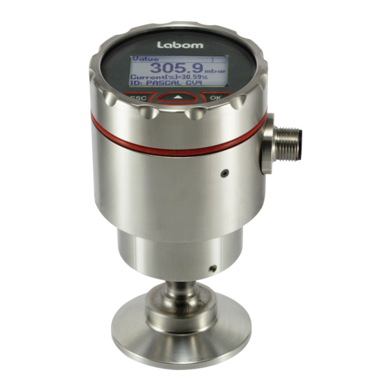
Pressure transmitter PASCAL CV4
Type series CV4xxx
BA_080_en_2022-01_11.02
Page 1/24
Advertisement
Table of Contents

Subscribe to Our Youtube Channel
Related Manuals for Labom CV4110


Summary of Contents for Labom CV4110
-
Page 1: Table Of Contents
6.2 Display Mode / Measured Value Display ..............7 6.3 Menue Mode / Operating Menue ................10 6.4 The Menue Tree ....................12 LABOM Mess- und Regeltechnik GmbH Im Gewerbepark 13 27798 Hude Germany BA_080_en_2022-01_11.02 Hotline: +49 4408 804-444 Fax: +49 4408 804-100 e-mail: sales@labom.com www.labom.com... -
Page 2: General Information
In addition to this instruction, be sure to observe all statutory requirements, applica- ble standards, the additional technical specifications on the accompanying data sheet (see www.labom.com) as well as the specifications indicated on the type plate. General Safety Notes The installation, set up, service or disassembly of this device must only be done by trained, qualified personnel using suitable equipment and authorized to do so. -
Page 3: Devices With Diaphragm Seal
Devices with Diaphragm Seal Remove the protective cap or protective wrapping from the diaphragm only just before in- stallation to prevent contamination or damage. The diaphragm must not be touched. Do not place the device on its diaphragm. Even small scratches or deformations may negatively influence the zero point or other characteristics of the device. -
Page 4: Electrical Connection
Electrical Connection Complete the mechanical installation before you connect the device electrically. Set up all electrical connections while the voltage supply is switched off. Output (2-wire) 4...20 mA (20...4 mA) = 12…30 VDC Permissible supply voltage ≤ (U Permissible load - 12 V) / 22 mA Circular connector M12 Cable gland... -
Page 5: Operation
Operation During operation, take care that the device remains within its intended pressure and tem- perature ranges. No other monitoring is necessary. -20…80 °C Permissible ambient temperature: Optionally, you can order devices with an extended ambient temperature range of -40...80 °C. Maintenance / Service When properly installed in accordance with applicable specifications, this device is mainte- nance-free. -
Page 6: User Manual
User Manual The device can be configured via the display module as well as the HART protocol. The following pages describe operation and configuration of the device using the display module. An overview of the menue structure can be found on the last page of this document. Basics of the Operating Concept The display module consists of a dot-matrix display with 80x128 pixels as well as a... -
Page 7: Display Mode / Measured Value Display
The icon for the device status (see 6.2.3) is displayed in each operating mode. The contents of the header and the data area depend on the operating mode: Display of measured value Header: Icon description, if applicable. Otherwise "Value" ... - Page 8 The sequence of the screens with device data is as follows: Min-/Max values (pressure and sensor temperature) ----- Measured value (starting point) --- Pressure measurement (nominal range, damping, etc.) Current output (characteristic curve, limits, measuring range) ...
- Page 9 6.2.4 Display layouts You can configure the layout of the measured value display as well as the displayed infor- mation individually. There are four different layouts available: Designa- Layout Description Example tion Four val- Under the main value, three additional values are shown.
-
Page 10: Menue Mode / Operating Menue
Menue Mode / Operating Menue Press OK in the measured value display to go to the operating menue. Then the main menue appears in the display. In the operating menue you can navigate in the menues by using the arrow buttons. The selected menue item is indicated by triangles on the left and right. - Page 11 6.3.1 Displaying and entering parameters When entering parameters, either numerical inputs or a selection lists with fixed options is available. In general, the actual selection will be displayed first (view mode). Press OK to switch to edit mode to change the parameter. After this is done, the display will then switch back to view mode so that you can check the new setting.
-
Page 12: The Menue Tree
Numeric values are entered digit by digit. First, always the leftmost digit is selected (visible with a triangle above and below the number). By pressing OK, you go to the next digit. parameter designation numeric value and unit Figure 6: Elements when setting a numeric value You change the selected digit by pressing the button. - Page 13 6.4.1 Main menue The main menue has the following entries: Menue entry Description Quick setup Selection of the most important settings Adjustment Adjustment functions for pressure measurement and current out- Display Functions for configuring the display Measurem./Output Configuration of the pressure measurement and current output Diagnosis Diagnostic information such as min/max values Simulation...
- Page 14 6.4.3 Menue "Adjustment" The following functions are available for the pressure adjustment: Menue entry Description Zero point Set device at ambient pressure to zero bar (not for absolute pressure devices) Position correct. Correct zero point error due to installation position (not for absolute pressure devices) Lower adjust.
- Page 15 6.4.3.3 Upper and lower adjustment The lower adjustment results in an offset of the characteristic curve. It thus affects zero and span of the measuring range. The upper adjustment changes the slope of the characteristic curve by correcting the span of the measuring range.
- Page 16 6.4.4 Menue "Display" In the "Display" menue, you find all the settings that affect the display on the screen. Menue entry Description Language Select menue language Units Setting units for the different measured and displayed values Screen mode Configuration of the screen layout and content (see 6.2.4) Decimal point Select setting of decimal point to determine number of decimal places Backlight...
- Page 17 Pressure unit The unit in which the measured pressure is to be shown can be selected from the following list: Unit Description mbar Millibar (1 mbar = 0,001 bar) Bar (1 bar = 1000 mbar = 10 Pascal (1 Pa = 1 kg/(m*s ) = 10 bar = 0,01 mbar) Hectopascal (1 hPa = 100 Pa = 1 mbar)
- Page 18 6.4.4.2 Submenue "Screen mode" In the "Screen mode" submenue, you configure the representation of the measured values and additional information on the display. With the menue item “Screen layout” you configure the information that is displayed and its layout. Up to four values can be displayed at the same time. In the additional menue entries "1st value"...
- Page 19 6.4.5.1 Setting the damping Using an adjustable damping you can eliminate fast pressure changes or peaks from having direct influence to the output signal. The set value in seconds corresponds to the time con- stant of an exponential rise. After a sudden pressure change, it takes the damping time to reach 63.2% of the actual pressure at the output.
- Page 20 6.4.5.4 Configuration of the table function With the table function you can realise any output function (display software version 1.1.0 and above). E.g. you can convert the fill height to the fill quantity depending on the tank shape. You can use up to 32 interpolation points for this purpose. Menue entry Description Number of points...
- Page 21 6.4.6 Menue "Diagnosis" In this menue you can view and configure various diagnostic information. The following di- agnostic functions are available: Menue entry Description Operating hours Display of operating hour counter Min/Max values Displaying and resetting the min/max values Last error Display and reset of the last critical error Table 15: "Diagnosis"...
- Page 22 6.4.8.2 Current mode The current mode determines whether the output current of the device is set to respond proportionally to the measured value (selection “proportional”) or whether it should remain constant at 4 mA (selection “constant”). When the current mode “constant” is in use, the measurement value can only be read using HART-commands (e.g.
- Page 23 BA_080_en_2022-01_11.02 Pressure transmitter PASCAL CV4 Page 23/24...
- Page 24 6.4.10 Overview with menue tree and device functions Quick Setup Select menu languag e Select unit for measured pressure Setting of the pressure value that should correspond to 4 mA (start of range) Setting of the pressure value that should correspond to 20 mA (end of range) Setting the damping of the output signal Setting the device ID Adjustment...
Need help?
Do you have a question about the CV4110 and is the answer not in the manual?
Questions and answers