Table of Contents
Advertisement
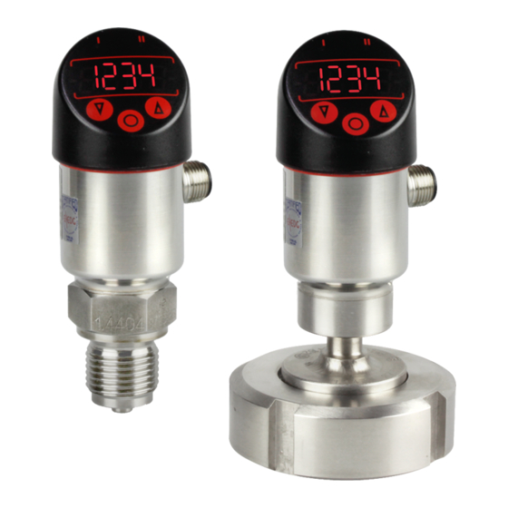
Operating Instructions for pressure transmitter
PASCAL CS
Table of contents
1
General Information ..................................................................................................... 2
1.1
Intended Use ........................................................................................................ 2
1.2
General Safety Notes............................................................................................ 2
1.3
CE Marking ........................................................................................................... 2
2
Transportation and Storage ......................................................................................... 2
3
Installation and Commissioning ................................................................................... 2
3.1
Electrical Connection ............................................................................................ 3
3.2
Adjusting the display unit ...................................................................................... 4
3.3
Devices with flush mounted diaphragm ................................................................ 4
4
Operation ..................................................................................................................... 5
4.1
Setup / Parameterization ...................................................................................... 5
4.2
Maintenance ......................................................................................................... 5
5
Removal....................................................................................................................... 5
6
User Manual................................................................................................................. 6
6.1
System operating principles.................................................................................. 6
6.2
Main menu .......................................................................................................... 10
6.3
Basic menu (bASE) ............................................................................................. 10
6.4
Display menu (diSP) .......................................................................................... 13
6.5
Switch-point menu .............................................................................................. 14
6.6
System menu...................................................................................................... 17
6.7
Overview of the menu tree.................................................................................. 18
Do you have questions about this device? Call our hotline at: +49 (0) 4408 804-444
LABOM Mess- und Regeltechnik GmbH · Im Gewerbepark 13 · 27798 Hude · Germany
Tel.: +49 (0) 4408 804-0 · Fax: +49 (0) 4408 804-100 · e-mail: info@labom.com · www.labom.com
, Type Series CS2100 and CS2110
BTA 060
Rev 1K1
Page 1/18
Advertisement
Table of Contents

Subscribe to Our Youtube Channel
Related Manuals for Labom PASCAL CS


Summary of Contents for Labom PASCAL CS
-
Page 1: Table Of Contents
Do you have questions about this device? Call our hotline at: +49 (0) 4408 804-444 BTA 060 Rev 1K1 LABOM Mess- und Regeltechnik GmbH · Im Gewerbepark 13 · 27798 Hude · Germany Tel.: +49 (0) 4408 804-0 · Fax: +49 (0) 4408 804-100 · e-mail: info@labom.com · www.labom.com Page 1/18... -
Page 2: General Information
In addition to these instructions, be sure to observe all statutory requirements, applicable standards, the additional technical specifications on the accompanying data sheet (see www.labom.com) as well as the specifications indicated on the type plate. 1.1 Intended Use The pressure transmitter PASCAL CS21xx is intended for measuring the relative and absolute pressure of gases, vapors and liquids as specified in the data sheet. -
Page 3: Electrical Connection
After the mechanical installation and the electrical connection are both complete, the device is ready for use as soon as the voltage supply is switched on. 3.1 Electrical Connection Make all electrical connections with the voltage supply switched off. Permissible supply voltage = 14 - 30 VDC Permissible load = (U... -
Page 4: Adjusting The Display Unit
Figure 4: Connecting options with shared high-side Use an appropriate free-wheeling diode, if you want to switch inductive loads. The default values fort he switching units are as follows, if not specified otherwise: switching unit 1 switching unit 2 output function hysteresis, normally open hysteresis, normally open switch point... -
Page 5: Operation
Operation During device operation, take care that the device remains within its intended temperature range, that its maximum operating pressure is not exceeded and that it is not harmed by the medium to which it is exposed. No other monitoring is necessary. Permissible ambient temperature: -20 °... -
Page 6: User Manual
User Manual This chapter describes the handling and parameterization of the device with the three buttons on the display head. You find an overview of the menu tree on the last page of this document. 6.1 System operating principles 6.1.1 System feedback to operator when buttons are pressed When you press a button, the switching output LEDs flash acknowledging the pressed button. - Page 7 Figure 5: Button functions in display mode, with example 6.1.4 Menu mode / Operator menu When you enter the menu mode, you always begin with the first main menu item (bASE).In menu mode you can navigate the menu with the arrow buttons. The middle button selects the menu item resp.
- Page 8 An example of button functions available in menu mode is shown below. Figure 7: Button functions in menu mode (example) For the sake of simplicity, the return to the next higher menu and directly to display mode will not be shown anymore. 6.1.5 Setting values There are two types of values that can be altered: −...
- Page 9 previous menu item of list entry parameter list list entry next list entry Figure 8: Button functions in a selection menu and example with parameter list for measuring units Setting a numerical value Numerical values are entered digit by digit. The selected digit flashes and is incremented with the up arrow button and decremented with the down arrow button.
-
Page 10: Main Menu
6.2 Main menu The main menu contains the following functions: Display Designation Description Basic functions Setting the unit, setting the zero point, min./max. pointer Display functions All settings relating to the display Switch point settings Configuration of the switching outputs (optional) System data Displaying system data (versions, serial... - Page 11 6.3.1 Setting the measuring unit (unit) The device can operate with the units shown below. The selected unit applies to data entries (e.g. for set points) and to the displaying of numerical values (e.g. the min./max. pointer). Display Unit Display Unit mbar Return...
- Page 12 Figure 11: Operator actions for correcting the zero point 6.3.3 Min. and max. pointers ( Lo / Hi ) The device has min./max. pointers for minimum and maximum pressure values. You can display and reset them in this menu. Resetting a pointer is confirmed by showing "----" on the display.
-
Page 13: Display Menu (Disp)
6.4 Display menu (diSP) The display menu for configuring the display contains the following items: Display Designation Description Display period for Can be set between 0.5 and 99.9 s measured value (time data) Display period for unit Can be set between 0.0 and 99.9 s (time unit) Rotate 180°... -
Page 14: Switch-Point Menu
6.4.3 Decimal-point setting (decP) You can set a fixed decimal point or allow the system to compute the best position for the decimal point. Display Designation Description Automatic The decimal point is set so that the decimal places are fully used No decimal place One decimal place Two decimal places... - Page 15 The switch-point (SP) must be between the upper range limit (URL) and the reset-point. The reset-point (rP) must be between the lower range limit (LRL) and the switch-point. The minimum distance between switch-point and reset-point (minimal hysteresis) is 0.5% of the measuring range.
- Page 16 6.5.1 Configuring the output function (out 1/2) You can choose a hysteresis or frame function as the output function. Furthermore you can define whether the output is normally open or normally closed. Display Designation Description Hysteresis, If the pressure is above the switch-point the normally open switch is closed.
-
Page 17: System Menu
6.6 System menu The system menu contains the following items. Display Designation Description Information Display of Hardware and software version, serial number Reset Reset to factory settings Return Return to "SYS" Table 14: The items in the system menu 6.6.1 Information (inFo) The following device information is available in the system menu. -
Page 18: Overview Of The Menu Tree
6.7 Overview of the menu tree Main menu Sub menu Description Menu with basic functions Setting the measuring unit (bar, mbar, PSI, %, kPa, MPa, mA) Setting the lower range (4 mA) to the applied pressure Display resp. delete the min. pointer Display resp.
Need help?
Do you have a question about the PASCAL CS and is the answer not in the manual?
Questions and answers