Labom PASCAL Ci4 Series Operating Instructions Manual
Pressure transmitter
Hide thumbs
Also See for PASCAL Ci4 Series:
- Sil instructions (4 pages) ,
- Operating instructions manual (36 pages) ,
- Manual (28 pages)
Table of Contents
Advertisement
Quick Links
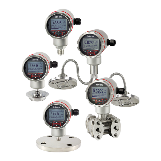
Pressure transmitter PASCAL Ci4
Type Series CI4xxx
Operating Instructions
1
General Information ...................................................................................................... 2
1.1
General Safety Notes .............................................................................................. 2
1.2
Intended Use ........................................................................................................... 2
1.3
Conformity with EU Regulations .............................................................................. 2
2
Transportation and Storage .......................................................................................... 2
3
Installation and Commissioning .................................................................................. 2
3.1
Mechanical Installation ............................................................................................ 2
3.2
Electrical Connection .............................................................................................. 3
3.3
Devices with Diaphragm Seal ................................................................................. 3
3.4
Mounting the Remote Display ................................................................................. 3
4
Operation ........................................................................................................................ 5
4.1
Test Terminals ........................................................................................................ 5
4.2
Remove Display / Activate Write Protection ............................................................ 5
4.3
Maintenance / Service ............................................................................................. 6
5
Disassembly ................................................................................................................... 6
6
User Manual ................................................................................................................... 7
6.1
Basics of the Operating Concept ............................................................................. 7
6.2
Display Mode / Measured Value Display ................................................................. 8
6.3
Menue Mode / Operating Menue ........................................................................... 11
6.4
The Menue Tree .................................................................................................... 13
Questions about this device? Hotline +49 (0) 4408 804 - 444
LABOM Mess- und Regeltechnik GmbH Im Gewerbepark 13 27798 Hude Deutschland
Tel.: +49 (0) 4408 804-0 Fax: +49 (0) 4408 804-100 e-mail: info@labom.com www.labom.com
BA_072
Rev 1J3
Seite 1/24
Advertisement
Table of Contents

Related Manuals for Labom PASCAL Ci4 Series


Summary of Contents for Labom PASCAL Ci4 Series
-
Page 1: Table Of Contents
BA_072 Questions about this device? Hotline +49 (0) 4408 804 - 444 Rev 1J3 LABOM Mess- und Regeltechnik GmbH Im Gewerbepark 13 27798 Hude Deutschland Seite 1/24 Tel.: +49 (0) 4408 804-0 Fax: +49 (0) 4408 804-100 e-mail: info@labom.com www.labom.com... -
Page 2: General Information
In addition to this instruction, be sure to observe all statutory requirements, applicable standards, the additional technical specifications on the accompanying data sheet (see www.labom.com) as well as the specifications indicated on the type plate. General Safety Notes The installation, set up, service or disassembly of this device must only be done by trained, qualified personnel using suitable equipment and authorized to do so. -
Page 3: Electrical Connection
Pressure transmitter and diaphragm seal are a closed system that must not be separated. You can find further information about diaphragm seals in the document TA_031 on www.labom.com. Mounting the Remote Display Optionally you can mount the display and control unit up to 10 m away from the measuring point in an additional housing. - Page 4 30 – 64 mm. For pipe mounting, you can order the corresponding U-bolts from LABOM. For best EMC protection, only use the included cable. If you ordered the remote display together with the device, the assembly has been completed in the factory.
-
Page 5: Operation
max. 10 m Figure 3: Remote display and control unit after installation Operation During operation, take care that the device remains within its intended pressure and temperature ranges. No other monitoring is necessary. Permissibe ambient temperature: -40…80 °C Test Terminals You can check the output current without interrupting the current loop, using the test terminals on the terminal board. -
Page 6: Disassembly
unscrew front cover turn display module 20° remove display module Figure 5: Removing the display After removing the display module you can reach the DIP switch on the CPU module. The write protection is active when the DIP switch is in the "ON" position. position write protection „ON“... -
Page 7: User Manual
Warning Opening pressurized lines might cause severe injuries. Danger of severy injuries or damage Relieve the process pressure before attempting to remove the device. Shut off the pressure supply for all feed lines to the device and relieve the pressure in them. -
Page 8: Display Mode / Measured Value Display
The structure of the display is the same in every operating mode. The display area is divided into four zones: Header Icon indicating device status Data area Bar graph related to the currently measured value Header Icon Data area Bar graph of... - Page 9 6.2.1 Quick Access to Device Data You can access a number of device parameters directly from the measured value display using the -buttons. This allows a quick overview of the device configuration. With the -button you can display variable data (trailing pointers and counters), with the -button static information such as configuration data.
- Page 10 The list of icons is sorted in descending priority. Only the icon with the highest priority is shown. The two most important icons for fault and/or warning are flashing when displayed. 6.2.3 Display layouts You can configure the layout of the measured value display as well as the displayed information individually.
-
Page 11: Menue Mode / Operating Menue
Menue Mode / Operating Menue Press OK in the measured value display to go to the operating menue. Then the main menue appears in the display. In the operating menue you can navigate in the menus by using the arrow buttons. The selected menue item is indicated by triangles on the left and right. - Page 12 6.3.1 Selection of a value from a selection list When opening a selection list, the currently set value is shown above the selection list. Up to three entries are shown at the same time. When the selection list is longer, a scroll bar on the left side of the display indicates the position of the selected item in the selection list.
-
Page 13: The Menue Tree
parameter designation help text numeric value unit bar graph Figure 12 Elements when setting a numeric value After selecting a menue item for numerical entry (e.g. upper range value), at first the value is only displayed. The numeric value itself is shown in square brackets and its the unit below. - Page 14 6.4.1 Main menue The main menue has the following entries: Menue entry Description Quick setup Selection of the most important settings Adjustment Adjustment functions for pressure measurement and current output Display Functions for configuring the display Measurement Configuration of the pressure measurement Current output Configuration of the current output Diagnosis...
- Page 15 6.4.3 "Adjustment" menue The following functions are available for the pressure adjustment: Menue entry Description Zero Point Set device at ambient pressure to zero (0 bar rel) (only for devices measuring gauge pressure) Position Correction Correct zero point error due to installation position (only for devices measuring gauge pressure) Lower Adjustment Offset correction with applied reference pressure...
- Page 16 measured 1) misaligned pressure characteristic curve 2) characteristic curve after lower calibration (offset shift) 3) characteristic curve after upper calibration (span correction) true pressure Figure 14: Effect of the upper and lower adjustment on the characteristic curve You can perform the upper and lower adjustment at any reference pressure level. For instance, you can perform the lower adjustment of a -1…4 bar device at -900 mbar rel.
- Page 17 6.4.4 "Display" menue In the "Display" menue, you find all the settings that affect the display on the screen. Menue entry Description Language Select menue language (German or English) Unit Pressure Select unit for measured pressure Unit Temperature Select unit for sensor temperature Display Mode Configuration of the display layout and content (see 6.2.3) Decimal point...
- Page 18 Please note that units can only be selected for nominal ranges that the device can display. For instance, the unit Pascal is hidden for nominal ranges above 1 bar. The unit selection in this submenue only affects the display on the screen. Communication via HART is performed using the unit set in the HART driver.
- Page 19 6.4.5.2 Setting the damping Using an adjustable damping you can eliminate fast pressure changes or peaks from having direct influence to the output signal. The set value in seconds corresponds to the time constant of an exponential rise. After a suddon pressure change, it takes the damping time to reach 63.2% of the actual pressure at the output.
- Page 20 6.4.6 "Current Output" menue In the "Current Output" menue, you configure all aspects of the current loop. Menue entry Description Output function Setting the output function (linear, inverse, square root, table) Table Specifying the interpolation points for the table function Alarm current Selection of the alarm current: High (>21 mA) or low (<3.6 mA) Lower current limit...
- Page 21 long long Figure 16: Changing a table point 6.4.6.2 Upper and lower current limit In the standard setting, the current output is limited at 3.8 and 20.5 mA, meaning a further drop or rise in the pressure does not change the current. You can freely select these current limits for the lower limit between 3.8 and 4 mA and for the upper limit between 20 and 21 mA.
- Page 22 Figure 17: Display and resetting of the trailing pointer for pressure 6.4.7.2 The maintenance timer Using the maintenance timer, the device can signal the need for maintenance after a freely selectable number of operating hours. The timer counts down from the start value. Maintenance need is indicated by an icon in the display (see 6.2.2) and, if necessary, the HART protocol.
- Page 23 6.4.9 "Communication" menue In the "Communication" menue the settings for the HART communication are summarised. Menue entry Description HART address Setting the HART address for device identification in multi-drop mode Current mode Setting the current mode (proportional/constant) HART data Display of HART information (HART tag, HART descriptor, etc.) Send-preambles Setting number...
- Page 24 6.4.11 Overview with menue tree and device functions Quick Setup Language… Select menu language (German or English) Unit Pressure… Select unit for measured pressure Unit Temperature… Select unit for sensor temperature Lower Value Range… Setting of the pressure value that should correspond to 4 mA (start of range) Upper Value Range…...
Need help?
Do you have a question about the PASCAL Ci4 Series and is the answer not in the manual?
Questions and answers