Labom PASCAL CV4 Operating Instructions Manual
Pressure transmitter
Hide thumbs
Also See for PASCAL CV4:
- Operating instruction (6 pages) ,
- Operating instructions manual (24 pages)
Table of Contents
Advertisement
Quick Links
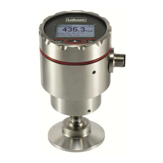
Pressure transmitter PASCAL CV4
Type series CV4xxx
Operating Instructions
1 General Information....................................................................................................... 2
1.1 General Safety Notes .............................................................................................. 2
1.2 Intended Use ........................................................................................................... 2
1.3 Conformity with EU Regulations .............................................................................. 2
2 Transportation and Storage .......................................................................................... 2
3 Installation and Commissioning .................................................................................. 2
3.1 Devices with Diaphragm Seal ................................................................................. 2
3.2 Mechanical Installation ............................................................................................ 3
3.3 Mount / dismount display ........................................................................................ 3
3.4 Electrical Connection .............................................................................................. 3
3.5 Device orientation ................................................................................................... 4
3.6 Adjustment of the display contrast .......................................................................... 4
4 Operation ........................................................................................................................ 4
4.1 Maintenance / Service ............................................................................................. 4
5 Disassembly ................................................................................................................... 5
6 User Manual ................................................................................................................... 6
6.1 Basics of the Operating Concept ............................................................................. 6
6.2 Display Mode / Measured Value Display ................................................................. 7
6.3 Menue Mode / Operating Menue ........................................................................... 10
6.4 The Menue Tree .................................................................................................... 13
Questions about this device? Hotline +49 (0) 4408 804 - 444
LABOM Mess- und Regeltechnik GmbH Im Gewerbepark 13 27798 Hude Deutschland
Tel.: +49 (0) 4408 804-0 Fax: +49 (0) 4408 804-100 e-mail: info@labom.com www.labom.com
BA_080
Rev 1J8
Page 1/24
Advertisement
Table of Contents

Related Manuals for Labom PASCAL CV4


Summary of Contents for Labom PASCAL CV4
-
Page 1: Table Of Contents
BA_080 Questions about this device? Hotline +49 (0) 4408 804 - 444 Rev 1J8 LABOM Mess- und Regeltechnik GmbH Im Gewerbepark 13 27798 Hude Deutschland Page 1/24 Tel.: +49 (0) 4408 804-0 Fax: +49 (0) 4408 804-100 e-mail: info@labom.com www.labom.com... -
Page 2: General Information
In addition to this instruction, be sure to observe all statutory requirements, appli- cable standards, the additional technical specifications on the accompanying data sheet (see www.labom.com) as well as the specifications indicated on the type plate. General Safety Notes The installation, set up, service or disassembly of this device must only be done by trained, qualified personnel using suitable equipment and authorized to do so. -
Page 3: Mechanical Installation
Otherwise, it is not possible to ensure a safe electrical connection. − Do not forget to tighten the cable gland after the electrical connection is finalised. BA_080 Rev 1J8 Pressure transmitter PASCAL CV4 Page 3/24... -
Page 4: Device Orientation
In case of damage or defects, the customer can replace the following elements: − Display module − Cable glands (if applicable) For defects to other components, repairs must be performed in the factory. BA_080 Rev 1J8 Pressure transmitter PASCAL CV4 Page 4/24... -
Page 5: Disassembly
After the device has been removed, seal off the measuring point and mark the open process connection accordingly. Consider a possible dan- ger due to residues when handling the removed device. BA_080 Rev 1J8 Pressure transmitter PASCAL CV4 Page 5/24... -
Page 6: User Manual
The structure of the display is the same in every operating mode. The display area is di- vided into three zones: − Header − Icon indicating device status − Data area Header Icon Data area Figure 3: Display structure BA_080 Rev 1J8 Pressure transmitter PASCAL CV4 Page 6/24... -
Page 7: Display Mode / Measured Value Display
From any screen of the device data, you can enter the operating menue with OK and go back to the measured value display by pressing ESC. BA_080 Rev 1J8 Pressure transmitter PASCAL CV4 Page 7/24... - Page 8 The list of icons is sorted in descending priority. Only the icon with the highest priority is shown. The two most important icons for fault and/or warning are flashing when displayed. BA_080 Rev 1J8 Pressure transmitter PASCAL CV4 Page 8/24...
- Page 9 "###" appears on the screen. Then select another layout or assign the value to a longer layout placeholder. You can configure the display mode in the menue "Display" submenue "Display mode" (see 6.4.4.2). BA_080 Rev 1J8 Pressure transmitter PASCAL CV4 Page 9/24...
-
Page 10: Menue Mode / Operating Menue
Select menue, confirm value/list entry Cancel the data entry or menue selection, return to the next higher menue ESC long Cancel menue mode, return to display mode Table 5: Button functions in the operating menue BA_080 Rev 1J8 Pressure transmitter PASCAL CV4 Page 10/24... - Page 11 Numeric values are entered digit by digit. First, always the leftmost digit is selected (visible with a triangle above and below the number). By pressing OK, you go to the next digit. BA_080 Rev 1J8 Pressure transmitter PASCAL CV4 Page 11/24...
- Page 12 When you confirm the rightmost digit, the entire value is saved. You can save the new val- ue from any digit by pressing and holding the OK button. Figure 7: Procedure for setting a numeric value (e.g. from 1.0 to 0.9) BA_080 Rev 1J8 Pressure transmitter PASCAL CV4 Page 12/24...
-
Page 13: The Menue Tree
Setting of the pressure value that should correspond to 20 mA (end of range) (see 6.4.5.3) Damping Setting the damping of the output signal (see 6.4.5.1) Device ID Setting the device ID (see 6.4.9.1) Table 7: "Quick-Setup" menue BA_080 Rev 1J8 Pressure transmitter PASCAL CV4 Page 13/24... - Page 14 The upper adjustment changes the slope of the characteristic curve by correcting the span of the measuring range. Execute the lower adjustment prior to the upper adjustment for a correct full adjustment. BA_080 Rev 1J8 Pressure transmitter PASCAL CV4 Page 14/24...
- Page 15 4 mA are shown at the end of the measurement chain. When leaving the function, the constant current mode is disabled and the current value corresponds again to the measured pressure. BA_080 Rev 1J8 Pressure transmitter PASCAL CV4 Page 15/24...
- Page 16 You can select the unit of every value shown on the display. These settings do not affect the internal calculations of the device or HART communication. The shown conversions are only meant for your orientation. The device uses conversion values with ten decimal places. BA_080 Rev 1J8 Pressure transmitter PASCAL CV4 Page 16/24...
- Page 17 Degree Fahrenheit ( T *1,8 + 32 ) Fahrenheit Celsius °R Degree Rankine ( T *1,8 ) Rankine Kelvin Kelvin ( T + 273,15 ) Kelvin Celsius Table 12: Possible units for temperature BA_080 Rev 1J8 Pressure transmitter PASCAL CV4 Page 17/24...
- Page 18 After a sudden pressure change, it takes the damping time to reach 63.2% of the actual pressure at the output. After the damping time has elapsed three times, 95% of the pressure is reached. BA_080 Rev 1J8 Pressure transmitter PASCAL CV4 Page 18/24...
- Page 19 You can freely select these current limits for the lower limit between 3.8 and 4 mA and for the upper limit be- tween 20 and 21 mA. BA_080 Rev 1J8 Pressure transmitter PASCAL CV4 Page 19/24...
- Page 20 Setting a fixed current value Pressure sim. Setting a fixed pressure value Table 15: "Simulation" menue The current simulation influences only the current output. The pressure simulation takes all settings into consideration, including the damping. BA_080 Rev 1J8 Pressure transmitter PASCAL CV4 Page 20/24...
- Page 21 Display of device data, such as from measured value display (see 6.2.1) Factory reset Reset to factory settings Device reset Restarting the device (such as after a power outage) Table 17: "System" menue BA_080 Rev 1J8 Pressure transmitter PASCAL CV4 Page 21/24...
- Page 22 When carrying out a factory reset, all parameters are set to the state at the time of deliv- ery. This also includes the pressure and current adjustment. Exceptions are the following operational parameters: “Min/max values”, “HART change counter” and “operation hours”. BA_080 Rev 1J8 Pressure transmitter PASCAL CV4 Page 22/24...
- Page 23 BA_080 Rev 1J8 Pressure transmitter PASCAL CV4 Page 23/24...
- Page 24 Setting the device ID (e.g. to display a free-text in the display) Device data… Display of device data (same as from measured value display) Factory reset… Reset to factory settings Device reset… Restarting the device (such as after a power outage) BA_080 Rev 1J8 Pressure transmitter PASCAL CV4 Page 24/24...
Need help?
Do you have a question about the PASCAL CV4 and is the answer not in the manual?
Questions and answers