Labom PASCAL Ci4 Series Manual
Pressure transmitter
Hide thumbs
Also See for PASCAL Ci4 Series:
- Sil instructions (4 pages) ,
- Operating instructions manual (36 pages) ,
- Operating instructions manual (24 pages)
Table of Contents
Advertisement
Quick Links
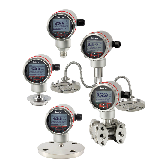
Pressure transmitter PASCAL Ci4
Type series CI4xxx
Operating Instructions
1 General Information....................................................................................................... 2
1.1 General Safety Notes .............................................................................................. 2
1.2 Intended Use ........................................................................................................... 2
1.3 Conformity with EU Regulations .............................................................................. 2
1.4 ATEX Approval ........................................................................................................ 2
2 Transportation and Storage .......................................................................................... 2
3 Installation and Commissioning .................................................................................. 2
3.1 Mechanical Installation ............................................................................................ 2
3.2 Electrical Connection .............................................................................................. 3
3.3 Devices with Diaphragm Seal ................................................................................. 3
3.4 Mounting the Remote Display ................................................................................. 4
4 Operation ........................................................................................................................ 5
4.1 Test Terminals ........................................................................................................ 5
4.2 Remove Display / Activate Write Protection ............................................................ 5
4.3 Adjustment of the display contrast .......................................................................... 6
4.4 Maintenance / Service ............................................................................................. 6
5 Disassembly ................................................................................................................... 7
6 User Manual ................................................................................................................... 8
6.1 Basics of the Operating Concept ............................................................................. 8
6.2 Display Mode / Measured Value Display ................................................................. 9
6.3 Menue Mode / Operating Menue ........................................................................... 12
6.4 The Menue Tree .................................................................................................... 15
LABOM Mess- und Regeltechnik GmbH Im Gewerbepark 13 27798 Hude Germany
Hotline: +49 4408 804-444 Fax: +49 4408 804-100 e-mail: sales@labom.com www.labom.com
BA_072_2020-02_10.00
Page 1/28
Advertisement
Table of Contents

Subscribe to Our Youtube Channel
Related Manuals for Labom PASCAL Ci4 Series


Summary of Contents for Labom PASCAL Ci4 Series
-
Page 1: Table Of Contents
6.2 Display Mode / Measured Value Display ..............9 6.3 Menue Mode / Operating Menue ................12 6.4 The Menue Tree ....................15 LABOM Mess- und Regeltechnik GmbH Im Gewerbepark 13 27798 Hude Germany BA_072_2020-02_10.00 Hotline: +49 4408 804-444 Fax: +49 4408 804-100 e-mail: sales@labom.com www.labom.com... -
Page 2: General Information
In addition to this instruction, be sure to observe all statutory requirements, appli- cable standards, the additional technical specifications on the accompanying data sheet (see www.labom.com) as well as the specifications indicated on the type plate. General Safety Notes The installation, set up, service or disassembly of this device must only be done by trained, qualified personnel using suitable equipment and authorized to do so. -
Page 3: Electrical Connection
Pressure transmitter and diaphragm seal are a closed system that must not be separated. You can find further information about diaphragm seals in the document TA_031 on www.labom.com. BA_072_2020-02_10.00 Pressure transmitter PASCAL Ci4 Page 3/28... -
Page 4: Mounting The Remote Display
The back plate of the housing is universally suitable for wall mounting or pipe mounting for pipe diameters from 30 – 64 mm. For pipe mounting, you can order the corresponding U-bolts from LABOM. For best EMC protection, only use the included cable. -
Page 5: Operation
Figure 3: Remote display and control unit after installation Operation During operation, take care that the device remains within its intended pressure and tem- perature ranges. No other monitoring is necessary. Permissible ambient temperature: -40…80 °C Test Terminals You can check the output current without interrupting the current loop, using the test ter- minals on the terminal board. -
Page 6: Adjustment Of The Display Contrast
Figure 5: Removing the display After removing the display module you can reach the DIP switch on the CPU module. The write protection is active when the DIP switch is in the "ON" position. Figure 6: Write protection via slide switch in the device Re-mount the display module in the reverse order. -
Page 7: Disassembly
Disassembly When measuring hot media, make sure that the device has cooled down prior to any dis- mounting or wear appropriate protective clothing to avoid burns. Switch off the power supply to the device before disconnecting the electrical connections. Once this is done, the device may be mechanically removed. Warning Opening pressurized lines might cause severe injuries. -
Page 8: User Manual
User Manual The device can be configured via the display module as well as the HART protocol. The following pages describe operation and configuration of the device using the display mod- ule. (valid from display module software version 2.0.0). An overview of the menue structure can be found on the last page of this document. Basics of the Operating Concept The display module consists of a dot-matrix display with 80x128 pixels as well as a... -
Page 9: Display Mode / Measured Value Display
The icon for the device status (see 6.2.3) as well as the bar graph is displayed in each op- erating mode. The bar graph always shows the state of the current output (4 mA = 0%, 20 mA = 100%). The contents of the header and the data area depend on the operating mode: Display of measured value ... - Page 10 The sequence of the screens with device data is as follows: Counter (operating hour counter, maintenance timer) Trailing pointer (pressure and sensor temperature) ----- Measured value display (starting point) --- Pressure measurement (rel/abs, nominal range, measuring range, damping) ...
- Page 11 6.2.4 Display layouts You can configure the layout of the measured value display as well as the displayed infor- mation individually. There are five different layouts available: Designation Layout Description Example Five values Under the main value, four additional values are shown. Four values Under the main value, three additional values are shown.
-
Page 12: Menue Mode / Operating Menue
Menue Mode / Operating Menue Press OK in the measured value display to go to the operating menue. Then the main menue appears in the display. In the operating menue you can navigate in the menues by using the arrow buttons. The selected menue item is indicated by triangles on the left and right. - Page 13 6.3.1 Displaying and entering parameters When entering parameters, either numerical inputs or a selection lists with fixed options is available. In general, the actual selection will be displayed first (view mode). Press OK to switch to edit mode to change the parameter. After this is done, the display will then switch back to view mode so that you can check the new setting.
- Page 14 Figure 11: Elements when setting a numeric value You change the selected digit by pressing the button. The higher value digit is also increased or decreased when passing zero. For instance, you can easily go from 19 to 20 without having to edit two digits. Lower value digits are not influenced, unless the parameter limit is reached.
-
Page 15: The Menue Tree
The Menue Tree In the following, the display and adjustment options are described by their position in the menue tree. An overview of the menue tree can be found on the last page of this docu- ment. 6.4.1 Main menue The main menue has the following entries: Menue entry Description... - Page 16 6.4.3 "Adjustment" menue The following functions are available for the adjustment: Menue entry Description Zero point Set device at ambient pressure to zero (0 bar rel) (not with abso- lute pressure devices) Position correction Correct zero point error due to installation position (not with abso- lute pressure devices) Lower adjustment Offset correction with applied reference pressure...
- Page 17 6.4.3.3 Upper and lower adjustment The lower adjustment results in an offset of the characteristic curve. It thus affects zero and span of the measuring range. The upper adjustment changes the slope of the characteristic curve by correcting the span of the measuring range.
- Page 18 6.4.4 "Display" menue In the "Display" menue, you find all the settings that affect the display on the screen. Menue entry Description Language Select menue language Units Setting units for the different measured and displayed values Screen mode Configuration of the screen layout and content (see 6.2.4) Decimal point Select setting of decimal point to determine number of decimal places...
- Page 19 Pressure unit The unit in which the measured pressure is to be shown can be selected from the following list: Unit Description mbar Millibar (1 mbar = 0,001 bar) Bar (1 bar = 1000 mbar = 10 Pascal (1 Pa = 1 kg/(m*s ) = 10 bar = 0,01 mbar) Hectopascal (1 hPa = 100 Pa = 1 mbar)
- Page 20 6.4.4.2 “Display mode” submenue In the "Display mode" submenue, you configure the representation of the measured values and additional information on the display. With the menue item “Screen layout” you configure the information that is displayed and its layout. Up to five values can be displayed at the same time. In the additional menue en- tries "1st value"...
- Page 21 6.4.5.1 Setting the damping Using an adjustable damping you can eliminate fast pressure changes or peaks from hav- ing direct influence to the output signal. The set value in seconds corresponds to the time constant of an exponential rise. After a sudden pressure change, it takes the damping time to reach 63.2% of the actual pressure at the output.
- Page 22 6.4.5.3 Output function You can set the output function proportionally rising to the measured value (selection "Lin- ear") or proportionally falling (selection "Inverse"). You can also define the output signal by a table with interpolation point, e.g. to represent a tank shape (selection "Table"). There is also a square root output function implemented for flow measurement per differ- ential pressure (selection "Square root").
- Page 23 Figure 15: Changing the table point Confirming inputs with a long OK is not available when editing table points. 6.4.5.6 Upper and lower current limit In the standard setting, the current output is limited at 3.8 and 20.5 mA, meaning a further drop or rise in the measured variable does not change the current.
- Page 24 6.4.6.1 Min/Max values The min/max values save the maximum and minimum values of the different measurands until they are reset by the user. The menue item that shows the min/max value, can also be used to reset it. Some of the min/max values are also directly accessible from the measured value display in the device data (see 6.2.1).
- Page 25 6.4.8 Menue "Communication" In the "Communication" menue the settings for the HART communication are summarised. Menue entry Description HART address Setting the HART address for device identification in multi-drop mode Current mode Setting the current mode (proportional/constant) HART data Display of HART information (HART-Tag, HART-Descriptor etc.) Send-preambles Setting of the number of send-preambles for HART communication...
- Page 26 6.4.9.1 Device ID Using the device ID, you can show a custom text in the display if you configure the display mode accordingly (see 6.2.4). For instance, you can show the tag number continuously in the display. The device ID can be up to 16 characters long and consist of numbers, empty spaces, capital letters and special characters.
- Page 27 BA_072_2020-02_10.00 Pressure transmitter PASCAL Ci4 Page 27/28...
- Page 28 6.4.10 1.1.1 Overview with menue tree and device functions BA_072_2020-02_10.00 Pressure transmitter PASCAL Ci4 Page 28/28...
Need help?
Do you have a question about the PASCAL Ci4 Series and is the answer not in the manual?
Questions and answers