Table of Contents

Related Manuals for Kodak DirectView CR 800 System


Summary of Contents for Kodak DirectView CR 800 System
- Page 1 {TheoryGuide}{Production}{HealthImaging} Publication No. TG3519-1 31MAR00 THEORY GUIDE for the KODAK DirectView CR 800 System Kodak Home Page on Internet Tech Bulletin on Intranet Table of Contents H177_0500GC © Eastman Kodak Company, 2000...
-
Page 2: Table Of Contents
Eastman Kodak Company reserves the right to change this information without notice, and makes no warranty, express or implied, with respect to this information. Kodak shall not be liable for any loss or damage, including consequential or special damages, resulting from any use of this information, even if loss or damage is caused by Kodak’s negligence or other fault. - Page 3 Power Distribution ............Overview .
- Page 4 Image Acquisition and Processing ......... . . Scanning Sequence .
-
Page 5: System Overview
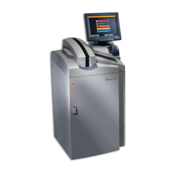
System Description The Kodak DirectView CR 800 System (CR 800) is a manual single-feed compact laser scanner. The CR 800 function is to read the latent image formed on a Storage phosphor imaging plate and produce a digital image, which can be viewed, enhanced, stored, printed, and distributed across a network. - Page 6 Kodak DirectView REMOTE OPERATIONS PANEL (ROP) A REMOTE OPERATIONS PANEL (ROP) is a separate device that can be Illustration: Remote Operations Panel attached to the wall at a location remote from any CR 800. It allows users to: With HANDHELD BARCODE READER •...
-
Page 7: Place In The Hospital / Clinical Setting
Kodak DigitalScience MEDICAL IMAGE MANAGER (MIM) and CR 800. Physical connections to the facility’s netward are via site-provided Category 5 cabling. Additionally, the customer must provide a Mitra Gateway Broker (or equivalent Kodak-qualified gateway device) to enable access to their HIS/RIS system. -
Page 8: Servicibility
Servicibility Easy access and servicibility has been designed and built into the CR 800 System. While the primary service will be performed on site, remote service capabilities make it possible for the Technical Service Center (TSC) to accesss service functions remotely. On-site Service Capabilities •... -
Page 9: Historical Perspective
O. Berg and H. Kaiser - Created contact radiographs on film with stimulated screens. 1970 - 1972 G. Luckey / Eastman Kodak Co. - Developed and patented a storage phosphor scanning system for radiography. (U.S. Pat. 3,859,527 in 1975). 1975 - today Worldwide research in computed radiography led to developments in materials, scanning systems, image processing capabilities, etc. -
Page 10: Computed Radiography (Cr) Theory
Section 2: Computed Radiography (CR) Theory From X-ray to CR In general X-rays are used in medical imaging to produce an image of specific anatomical features on a surface, which can be interpreted by a radiologist or other medical personnel. There are three basic phases to both conventional X-ray systems (screen/film) and computed radiography such as the CR 800. Producing the Aerial Image In both conventional and computed radiographic systems, X-rays are produced in an X-ray tube and directed toward an image receptor. -
Page 11: Cr Overview
Computed Radiography (CR) Theory CR Overview Computed Radiography (CR) is the common term used when referring to the digital acquisition of projection radiographs. A number of operations is required in order to capture the latent image stored in the storage phosphor screen and turn it into a digital image that can be viewed on a computer screen and printed out. These operations. -
Page 12: Exposing The Storage Phosphor Plate
Exposing the Storage Phosphor Plate When the storage phosphor screen is exposed to X-rays, the special phosphors on the screen absorb the radiation in varying degrees of intensity depending on the body part and the screen type, for example, high resolution screens absorb less energy. After exposure, the screen has a “latent” image where the screen was exposed to the radiation. -
Page 13: Stimulating The Phosphor
Computed Radiography (CR) Theory Stimulating the Phosphor Stimulating Light Source Acquiring the latent image off the phosphor screen is accomplished by exposing the screen with high intensity light that stimulate the electrons, causing them to luminesce. Efficient read-out of the screen requires a high stimulating light Illustration showing the movement of the beam across the intensity, such as that offered by a laser beam. -
Page 14: From Light Energy To Analog Signal
From Light Energy to Analog Signal Collector Blue light is emitted from the phosphor when it is stimulated by the laser beam. Illustration showing the relationship of the collector to the The emitted light goes in all directions. Therefore, a light collector is optimally emitted light. -
Page 15: From Analog To Digital
Computed Radiography (CR) Theory From Analog to Digital Converting the Image Data The next step is converting the analog signal into a digital signal by sampling the blue light that comes off the plate and passing it through an analog-to-digital Analog to digital transformation. -
Page 16: Analog (Film) Vs. Digital (Computer Radiography) Comparison
Analog (Film) vs. Digital (Computer Radiography) Comparison Analog Screen / Film Systems Digital Computer Radiographic Systems “Rare Earth” screens - Gadolinium Oxysulfide or Lanthanum Oxybromide. Phosphor screen - Barium Flourohalide. Speed range from 100 to 1000 Screen speed: • General Purpose (GP), 200 - 250 •... -
Page 17: Working With The Kodak Cr 800 System
Section 3: Working with the KODAK CR 800 System Due the the flexible configuration possiblities, a KODAK CR 800 System can be designed to the specific workflow needs of any department or imaging center that requries digital radiographs, thus providing increased department thougput by providing optimized images where they are needed when they are needed. A CR 800 can even be placed in the X-Ray room eliminating the need for the radioprapher to leave the exam room for PLATE processing. - Page 18 3–18 12/12/94 – 1234563...
-
Page 19: Cr 800 Storage Phosphor Cassettes
CR 800 STORAGE PHOSPHOR CASSETTES Section 4: CR 800 STORAGE PHOSPHOR CASSETTES CASSETTE Description CASSETTES A STORAGE PHOSPHOR CASSETTE consists of: CASSETTE SHELL The SHELL is composed of a carbon fiber front and an aluminum back, open on one side for removal and insertion of the phosphor plate. -
Page 20: Size And Resolution
Size and Resolution Sizes and Resolutions of Kodak STORAGE PHOSPHOR SCREENS The 35 cm x 43 cm CASSETTE is new and can be used only in CR 800 Systems. The PLATE is removed from the CASSETTE in a direction 90 degrees from the... -
Page 21: Reading The Barcode Label
CR 800 STORAGE PHOSPHOR CASSETTES Reading the BARCODE LABEL Reading the BARCODE LABEL Digit Represents Illustration variation: Constant value of “0” H141_0015HC H141_0015HCA 1 = General Purpose (GP) 2 = High Definition (HR) 3rd and 4th Size: 01 = 18 x 24 cm 02 = 24 x 30 cm 03 = 35 x 35 cm 04 = 35 x 43 cm... -
Page 22: Power Distribution
Section 5: Power Distribution Overview Acceptable Power Sources The CR 800 will function properly when conected to power sources ranging from 90 to 264 V AC ?? this is not what it says on the chart but what it says on Nominal( V AC) V Tolerance Current( AMPs) Frequency (Hz) -
Page 23: Electrical Path
Power Distribution Electrical Path Illustration of Power Distribution from wall outlet throughout the CR 800, including the components listed below. Power Distribution Components S8 INTERLOCK SWITCH The S8 INTERLOCK SWITCH controls relays on the A1 MSC BD, which in turn controls the 24 V DC power to the the DC components, including the MOTORS, SOLENOIDS, and the LASER SHUTTER. -
Page 24: Logic And Control
Section 6: Logic and Control Diagram Communication ??is there anything I should say here?? 6–24 12/12/94 – 1234563... -
Page 25: Circuit Boards (Bds)
Logic and Control Circuit Boards (BDs) A1 MOTION SYSTEM The A1 MSC BD is responsible for controlling the electro-mechanical devices in the CR 800 System. The primary functions include: CONTROL (MSC BD) • Controlling/restricting motion of the CASSETTE • Controlling the extraction and re-insertion of the PLATE from/into the CASSETTE. •... - Page 26 A6 SLOW SCAN The A6 SLOW SCAN CONTROLLER BD is a microprocessor controlled circuit board that controls the operation of the SLOW SCAN CONTROLLER (SSC BD) MOTOR. The A6 is responsible for accurately controlling all vertical movement of the PLATE in a constant linear motion perpendicular to the direction of the LASER sweep.
-
Page 27: Cassette Handling / Plate Handling
Cassette Handling / Plate Handling Section 7: Cassette Handling / Plate Handling Function Illustration of the Cassette Handling Sub assembly, with callouts to the various components that would follow. The function of Cassette Handling is to move the CASSETTE into position in the CR 800 so that the PLATE can be extracted for scanning. Plate Handling involves unlatching the PLATE and hooking it onto the EXTRACTION BAR. -
Page 28: Duplex Cam And Related Components
DUPLEX CAM and Related Components The unique design of the DUPLEX CAM enables a single mechanical component to actuate many movements in theCASSETTTE and PLATE handling sequence of operations. The DUPLEX CAM is essentially 2 CAMS, the SLED CAM and the HOOK CAM, each with separate functions. -
Page 29: Index Positions Of The Duplex Cam
Cassette Handling / Plate Handling Index Positions of the DUPLEX CAM four CAM positions from M. Poccia’s .DWG file. The position of the DUPLEX CAM is verified by reading the S10 and S11 SENSOR status after a move. After the position is verified,the MSC BD directs the CAM MOTOR to index the DUPLEX CAM to the next position. -
Page 30: Cassette Handling Sensors
Cassette Handling Sensors Ill. S1, S2, S3, S4 S1 CASSETTE ENTRY SENSOR These optical sensors (LED/Phototransistor) are located at the cassette entry and load positions of the CASSETTE S2 CASSETTE LOAD ENTRY SENSOR HANDLING AY. The emitters of each are located on one side of the entrance with the detectors directly opposite each respectively. -
Page 31: Cassette Transport Components
Cassette Handling / Plate Handling CASSETTE Transport Components LEFT FRONT ROLLER AY The LEFT and RIGHT FRONT DRIVE ROLLER AYs each consist of 3 ROLLERS, mounted on a SHAFT. The RIGHT RIGHT FRONT ROLLER AY ROLLER AY is stationary, whereas the LEFT ROLLER AY is moveable. The top 2 rollers of both assemblies are made of soft plastic. -
Page 32: Plate Handling Components
PLATE Handling Components HOOK CAM The HOOK CAM is formed by the outer rim of the DUPLEX CAM. As the DUPLEX CAM indexes through the positions 1 - 4, the HOOK CAM initiates the actions for hooking and unhooking the PLATE to the EXTRACTION BAR . -
Page 33: Components For Guiding The Plate
Cassette Handling / Plate Handling Components for Guiding the PLATE PLATE GUIDE AY The PLATE GUIDE ASSEMBLY functions to enable the EXTRATION BAR to pass when it moves up and down. In addition, the PLATE GUIDE AY has 2 sets of PLATE Plate Guide Ay GUIDE ROLLERS that position the PLATE for optimal scanning. -
Page 34: Scan/Erase Subsystem
Section 8: Scan/Erase Subsystem Function/Components The Scan/Erase Subsystem is responsible for moving the STORAGE PHOSPHOR PLATE through the field of scan at a uniform velocity, then moving it to the erase position where it is erased, and finally moving it back up to be inserted into the CASSETTE SHELL. LEAD SCREW The LEAD SCREW is coupled to the MOTOR SHAFT. -
Page 35: Scan/Erase Positions
Scan/Erase Subsystem Scan/Erase Positions There are 4 distinct vertical positions of the EXTRACTION BAR. These positions are monitored by the S9 REFERENCE SENSOR and by ENCODER COUNTS that are defined when the system is set up at the factory. . REFERENCE Position of the EXTRACTION BAR when the S9 SENSOR Position... -
Page 36: Slow Scan Operation
Slow Scan Operation Three main components are involved in SLOW SCAN operation: • A6 SLOW SCAN CONTROLLER BD • SLOW SCAN MOTOR, including Illustration of Basic Slow Scan subsystem components – STEEL PLATE, which works with the A7 COIL BD to generate the magnet which creates torque in the MOTOR. -
Page 37: A7 Coil Bd Operation
Scan/Erase Subsystem A7 COIL BD Operation A7 COIL BD Components The A7COIL BD is made up of: • 6 triangular-shaped coils of wire, arranged around the central SHAFT of the Illustration detail of COIL BD. MOTOR. • 3 HALL EFFECT SENSORS, which detect magnetic fields. They are used in the MOTOR to determine the position of the MAGNET poles relative to the coils. -
Page 38: Encoder Operation
ENCODER Operation The ENCODER monitors the speed and position of the MAGNET in its rotation to ensure extreme smoothness and constant velocity. The ENCODER is made up • ENCODER WHEEL, which is a clear disk that has been printed with 5000 lines leading from the center to the outer edge. -
Page 39: Optical Subsystem
OPTICAL Subsystem Section 9: OPTICAL Subsystem Overview The CR 800 OPTICAL AY is responsible for 3 main processes: • Generating and focusing the red LASER beam onto the STORAGE PHOSPHOR PLATE. • Moving the LASER beam across the plate at a controlled rate in the fast scan direction to discharge the stored energy in the phosphors. See “Operation of the GALVO System??not an official name?any ideas?.”... -
Page 40: Operation Of The Galvo System??Not An Official Name?Any Ideas
Operation of the GALVO System??not an official name?any ideas? The main purpose of the GALVO system is to rotate a mirror to cause the beam of the LASER to scan across the PHOSPHOR PLATE (fast scan), do a quick retrace, and scan another line until the entire plate has been scanned. - Page 41 OPTICAL Subsystem Detailed Operation of the A4 GALVO BD ??All apologies to Doug. Below is an attempt to provide a more detailed description, but to make it less technical. I don’t know how well I’ve succeeded. 1. To set up for a PLATE scan, the system (WHAT?) sets the plate-size-select inputs to the State Machine for the PLATE being scanned, that is, the plate width and the number of lines to be scanned ?? is this true?.
- Page 42 Desired Position Signal - Velocity vs. Time This will be a chart showing the signal both time and velocity. I need help here, both in drawing it, and in any textthat should accompany the graphical representation. This is a pretty bad drawing program, but it is just to give you an idea.
-
Page 43: Pmt System ?? This Is Not An Official Name Of Anything?? What Should I Call It
OPTICAL Subsystem PMT System ?? This is not an official name of anything?? what should I call it? The purpose of the PMT system is to collect the blue light emitted from the PHOSPHOR PLATE when the PLATE is scanned, measure its intensity, and convert the measurement to digital format. - Page 44 Operation of the PMT System Collecting the Blue Light When the red beam of the LASER strikes the PLATE, blue light is emitted in Collecting the blue light; overview, fig. 1 from Doug’s drawing. random directions. The COLLECTOR and NOSEPIECE are designed to capture as many of the rays of blue light as possible and direct them toward the face of the PMTs.
- Page 45 OPTICAL Subsystem Operation of the PMT/DAS BD This will be some subsample of the PMT/DAS BD block diagram from D. Seim. I’mnot sure how to simplify this and get the important details for this audience. Same problem with the Galvo Bd. Also, I’m not sure how much of Doug’s explanation to include.
- Page 46 5. The filtered signal is then set to the 16 BIT A/D CONVERTER for measurement. This is the measurement of the intensity of the blue light that was emitted by the PHOSPHOR PLATE. 6. Recall that the intensity of the blue light is proportional to the charge stored by the phosphor and the intensity of the laser beam that struck the phosphor. In order to reconstruct the original image, we need to know how strong the laser beam was when the blue light was measured.
-
Page 47: Error And Activity Logs
Error and Activity Logs Section 10: Error and Activity Logs The CR 800 logs error, activity, and actuation information. All logs are created on the INTERNAL PC. They are time stamped, written in English, and can be accessed from a remote location by authorized Service Personnel. ?Maybe this is superfluous since there is more and better information in diagnostics?? Should it just be eliminated? Error Reporting / Logs There are essentially 2 kinds of errors reported by the system, errors that the user... -
Page 48: Activity Logs
Activity Logs Activity Logs maintain a record of all system actuations (scan ?? what defines an actuation>??). These Logs are available to Key Operator Personnel and authorized Service Personnel. Activity logs can be sorted by Cassette ID, Date, Time, Technician ID, ??? •... -
Page 49: Sequence Of Operations
SEQUENCE OF OPERATIONS Section 11: SEQUENCE OF OPERATIONS Initialization ?? THIS WILL COME FROM THE MEETING NOTES FROM DOUG SEIM.?? CASSETTE HANDLING / PLATE Handling CASSETTE Handling involves two operations - loading the CASSETTE into the CR 800 and unloading the CASSETTE from the CR 800 CASSETTE Loading [1] Prior to loading a CASSETTE into the CR 800: •... - Page 50 [5] The INTERNAL BARCODE READER reads the CASSETTE size, speed, and serial number and: • Issues an audible tone. • Sends: – a “Cassette Detected” message to the MCPU. – the CASSETTE size (length and width) to the MCPU. [6] The MCPU sends: •...
- Page 51 SEQUENCE OF OPERATIONS [10] The SLED CAM indexes to position 2. (a) The SLED PLATE moves.250 in. forward. (b) If the CASSETTE is: 35cm x 35cm The LEFT FRONT ROLLER AY moves to the 35cm x 43cm right to Pinch position, which pinches the CASSETTE against the RIGHT FRONT ROLLER AY.
-
Page 52: Plate Handling Operations
Plate Handling Operations PLATE Extraction [1] The DUPLEX CAM indexes toward Position #3. As it rotates, both the SLED CAM and the HOOK CAM execute specific actions. The first few degrees of the CAM rotation pushes the HOOKS up. The rest of the rotation, unlatches the CASSETTE and hooks the PLATE to the EXTRACTION BAR. SLED CAM actions on way to DUPLEX CAM position #3 HOOK CAM actions on way to DUPLEX CAM position #3 a. -
Page 53: Scan Operation
SEQUENCE OF OPERATIONS Status: PLATE HOOKED • CAM has reached position #3. • SLED is.600 in. forward of Home position. • CASSETTE is firmly clamped by the DRIVE ROLLERS (FRONT or MIDDLE) and the CASSETTE REAR ROLLERS. • CASSETTE is unlatched •... - Page 54 [1] The SLOW SCAN MOTOR starts turning the LEADSCREW, pulling the PLATE out of the CASSETTE and downward. Note When the PLATE leaves the CASSETTE, the EXTRACTION BAR holds the PLATE in a 1 degree tilt to the left. [2] As the EXTRACTION BAR moves down, it rides along the UPPER PLATE GUIDE CAM and the LOWER PLATE GUIDE CAM.
- Page 55 SEQUENCE OF OPERATIONS Status: Preparation for Scanning • SLOW SCAN MOTOR is stopped. • PLATE is at the NOSEPIECE Engaged position. • NOSEPIECE is engaged • LASER SHUTTER is open. • LASER POWER is on and verified. • PMTs are on high current. •...
- Page 56 [5] When the End of Scan is reached, the MSC sends a status message to the MCPU. [6] The MSC turns the L2 SOLENOID off which disengages the NOSEPIECE. [7] The NOSEPIECE CLEAR SENSOR, S6, detects that the NOSEPIECE is in the Clear position.
-
Page 57: Inserting The Plate And Unloading The Cassette
SEQUENCE OF OPERATIONS Inserting the PLATE and Unloading the CASSETTE Inserting the PLATE [1] As soon as the MCPU receives the Erase Done status, it issues a command to the MSC TO Eject the PLATE and to return to Home position. [2] The MSC starts the SLOW SCAN MOTOR moving in reverse direction, which moves the PLATE upward into the open CASSETTE. -
Page 58: Communication / Networking And Routing
[8] The DUPLEX CAM indexes to Home position #1. (a) The SLED moves.250 in. rearward, which moves the CASSETTE into the CASSETTE LOAD STATION. (b) The FRONT DRIVE ROLLERS are unpinched. [9] The MSC reports the Cassette Ejected status to the MCPU. [10] After the Operator removes the CASSETTE from the LOAD STATION, the MSC sends a Scan End status to the MCPU. -
Page 59: Image Acquisition And Processing
Image Acquisition and Processing Section 12: Image Acquisition and Processing Image acquisition and processing involves 3 primary sequences: scanning, acquisition, and processing. Throughout these processes much of the activity is synchronized by the Digitizer BD and the Galvo ??BD??. Scanning Sequence Pre-scanning Conditions Prior to the optical start of scan, the Plate has reached the mechanical Start of Scan. -
Page 60: Fast Scan
Fast Scan The Fast Scan direction is a nearly horizontal path across the plate. While the PLATE is moving down in the Slow Scan direction each line of the Fast Scan begins one pixel line higher up on the PLATE. The distance the LASER travels both vertically (Slow Scan) and horizontally (Fast Scan) is set up in configuration for each PLATE size. - Page 61 Image Acquisition and Processing [1] The red LASER beams scans across the plate in the fast scan direction. As it encounters a charged phosphor (by the x-ray exposure), it causes the phosphor to emit blue light. The intensity of the blue light is proportional to the strength of the incident X-ray and the power of the laser at the point it strikes the phosphor. The light is emitted in a random fashion.
- Page 62 Important The LASER power is known constantly by the Laser Reference data. With each sampling point (in time) that the LASER reads on the PLATE, the REF BD is reading the reference signal. This data will be used later by the MCPU to make corrections to the image data. [2] The random light is picked up by the NOSEPIECE of the COLLECTOR which reflects it toward the faces of the 5 PMTs See “PMT...
-
Page 63: Processing The Data
Image Acquisition and Processing Processing the Data At this point, the image is still just a number of independent measurementsof blue light intensity that have been read off the Plate, filtered, summed, converted from light energy to current, converted again from an anolog signal to a 16 bit digital signal, and combined with 16 bits of Laser reference data to make up a 32 bit word. Each 32 bit word represents a “pixel”... - Page 64 [1] The two 16 bit values are sent to a FIFO buffer on the DIGITIZER BD where it is buffered until a complete line of data, depending on the screen size) is accumulated. [2] In very rapid succession, while the GALVO is doing the retrace (quick movement back to the 0 position at roughly10X the speed of the trace): (a) The 32 bit line times the number of pixels in the line (for example 32 X 2048) is moved via DMA to the MCPU.
-
Page 65: Image Processing
Image Acquisition and Processing [7] When the scan is complete (both the mechanical “end of scan” and the optical “end of scan”), both areas report to the MCPU that they are done. The MCPU then directs the Erase Plate sequence. Image Processing [1] When the software on the PC detects that a raw image has come from the MCPU, it: (a) Puts the data into a prepared RAW_Image file... - Page 66 [5] The MIM software makes one copy of the 10 mg file and sends from that file to all destinations, depending on the destination and what that destination can be handed?? what does that mean?? The MIM tries 3 times to send the file. If it fails after 3 tries, it erases the file and reports the action to the NT where the original file is stored.
-
Page 67: Glossary
Glossary Section 13: Glossary 1234563 – 12/12/94 13–67... - Page 68 13–68 12/12/94 – 1234563...
Need help?
Do you have a question about the DirectView CR 800 System and is the answer not in the manual?
Questions and answers