
Subscribe to Our Youtube Channel
Related Manuals for UTC Fire and Security KiddeFire Systems ARIES NETLink BACnet


Summary of Contents for UTC Fire and Security KiddeFire Systems ARIES NETLink BACnet
- Page 1 P/N 06-237214-002 June 2012 ARIES NETLink ™ BACnet Interface ® Module User’s Guide A UTC Fire & Security Company...
-
Page 3: Foreword
FOREWORD Note: This Instruction Manual, P/N 06-237214-002, is to be used by qualified and factory-trained personnel, knowledgeable of NFPA standards and all local codes in effect. This manual is intended to clearly and accurately reflect the BACnet Interface Module. This publication ®... -
Page 4: Table Of Contents
TABLE OF CONTENTS Foreword .......................i Table of Contents....................ii List of Figures ......................iii List of Tables......................iv CHAPTER 1 GENERAL INFORMATION Product Description ................1-1 Installation Overview................1-2 1-2.1 Wiring Diagrams ................... 1-2 Components Overview ................1-5 1-3.1 Grounding.................... 1-5 1-3.2 DIP Switches ..................1-6 1-3.3 Light Emitting Diodes (LEDs) .............. -
Page 5: List Of Figures
LIST OF FIGURES Figure Name Page Number Overview of BACnet Interface Module(s) ..............1-1 Wiring Diagram for BACnet Interface Module ............1-3 Wiring Diagram for BACnet Interface Module with Add-On Module ......1-4 The BACnet Interface Module ................1-5 BACnet Interface Module DIP Switches ..............1-6 LEDs on BACnet Interface Module ProtoCessor Board.......... - Page 6 LIST OF TABLES Table Name Page Number “B Bank” DIP Switch Settings ................1-6 “S Bank” DIP Switch Settings ................1-6 ProtoCessor Board LED Functionality ..............1-7 Main Board LED Functionality ................1-8 Default Communication Settings ................1-9 BACnet Event State Mapping for ARIES NETLink............1-10 BACnet Multi-State Input Mapping for ARIES NETLink Systems With 4 or Fewer SLCs..
-
Page 7: Chapter 1 General Information
General Information CHAPTER 1 GENERAL INFORMATION PRODUCT DESCRIPTION ® The BACnet Interface Module is an external, high performance Building Automation multi- protocol gateway that has been pre-programmed for the ARIES NETLink control unit to support both BACnet MS/TP and BACnet/IP protocols. Configuration of the BACnet Interface Module is programmed to support Modbus RTU signal output from the ARIES NETLink. -
Page 8: Installation Overview
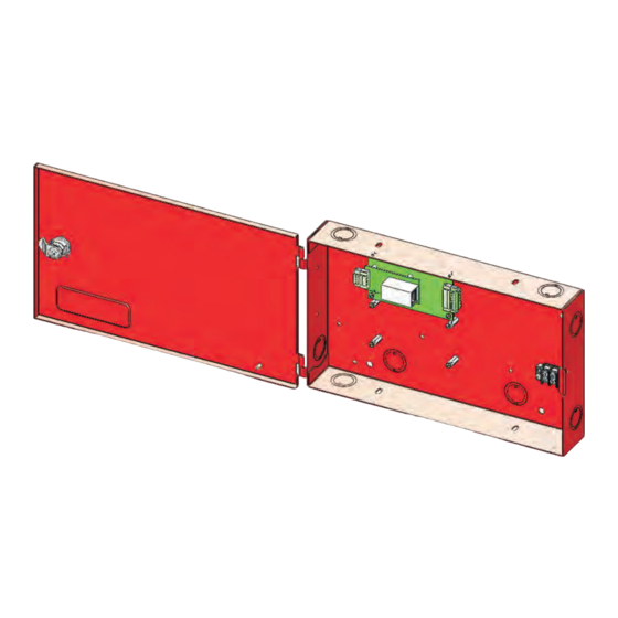
General Information INSTALLATION OVERVIEW The BACnet Interface Module is provided as a single module mounted inside the standard ARIES NETLink remote enclosure. The single module supports systems with up to 4 Signaling Line Circuits (SLCs). For systems including more than 4 SLCs, a second (Add-On) module is required. - Page 9 General Information P/N 06-237214-002 June 2012...
- Page 10 General Information June 2012 P/N 06-237214-002...
-
Page 11: Components Overview
General Information COMPONENTS OVERVIEW Key components of the BACnet Interface Module are shown in the photograph below. 3-Pin Connector for BACnet MS/TP network End-Of-Line Switch “A Bank” DIP Switches ProtoCessor Board “B Bank” DIP Switches “S Bank” DIP Switches Main Board ProtoCessor Board LEDs Ethernet port for BACnet/IP network Main Board LEDs... -
Page 12: 1-3.2 Dip Switches
General Information 1-3.2 DIP Switches Three banks of DIP Switches are located on the Main Board. Refer to Figure 1-5 below: Note: When setting DIP switches, ensure that power to the board is OFF. Switches A0 through A7 Switches B0 through B3 (set at the factory to an address (set at the factory to a value of “38400”;... -
Page 13: 1-3.3 Light Emitting Diodes (Leds)
General Information 1-3.3 Light Emitting Diodes (LEDs) LEDs are included on the ProtoCessor board (see Figure 1-6) and the Main Board (Figure 1-7). Refer to Table 1-3 (ProtoCessor LEDs) and Table 1-4 (Main LEDs) for a brief description of LED functionality. -
Page 14: Leds On Bacnet Interface Module Main Board
General Information Figure 1-7 shows the location of the LEDs located on the Main Board: RTC (Unused) Figure 1-7. LEDs on BACnet Interface Module Main Board Table 1-4. Main Board LED Functionality Light Description RUN The RUN LED will start flashing 20 seconds after power indicating normal operation. The SYS ERR LED will go on solid 15 seconds after power up. It will turn off after 5 seconds. A steady red light will indicate there is a system error on the module. If this occurs, immediately report the related “system error” shown in the error ERR screen of the RUI interface to Fenwal Protection Systems Technical Support for evaluation. The RX LED will flash when a message is received on the RS232 port. -
Page 15: Enabling Modbus On The Control Unit
General Information ENABLING MODBUS ON THE CONTROL UNIT Modbus must first be enabled on the appropriate RS232 port of the ARIES NETLink control unit to allow each BACnet Interface Module to communicate. It is necessary to do the following: 1. Identify the RS232 port on the ARIES NETLink MCB where the BACnet Interface Module is connected (either “RS232A”... -
Page 16: Status Data Mapping
General Information STATUS DATA MAPPING The ARIES NETLink control unit statuses are mapped to BACnet Event States as shown in Table 1-6 below: Table 1-6. BACnet Event State Mapping for ARIES NETLink Control Unit Status BACnet Object Event State 0x1; fault Supervisory Trouble 0x1;... -
Page 17: 1-6.2 Systems With 5 To 8 Slcs (Two Bacnet Interface Modules)
General Information 1-6.2 Systems With 5 to 8 SLCs (Two BACnet Interface Modules) For a ARIES NETLink system with 5 or more (up to 8 maximum) Signaling Line Circuits (SLCs), the control unit data is mapped to BACnet Multi-State Inputs as shown in Table 1-8 below: Table 1-8. -
Page 18: Specifications
General Information SPECIFICATIONS Table 1-9. BACnet Interface Module Specifications Electrical Connections One 6‐pin Phoenix connector, one RS‐485 +/‐ ground port, power +/‐ frame ground port One 3‐pin RS‐485 Phoenix connector, one RS‐485 +/‐ ground port One Ethernet‐10/100 Ethernet port BACnet Testing Laboratory (BTL) Marked Approvals 9 ‐ 30VDC or 12 ‐ 24VAC Power Requirements 4.5 in. L x 3.2 in.W x 1.6 in. H (11.5 cm L x 8.2 cm W x 4.0 cm H ) Physical Dimensions 0.4 lbs (0.2 kg) Weight ‐40°F to 167°F (‐40°C to 75°C) Operating Temperature EN61000‐4‐2 ESD EN61000‐4‐3 EMC EN61000‐4‐4 EFT Surge Suppression 5 ‐ 90% RH (non‐condensing) Humidity 192.168.1.24 Default BACnet/IP Address Default BACnet MS/TP Address 8 (“A Bank” DIP Switch Setting) Note: Specifications are subject to change without notice. June 2012 1-12 P/N 06-237214-002... -
Page 19: Chapter 2 Bacnet/Ip
BACnet/IP CHAPTER 2 BACNET/IP INTRODUCTION ® This chapter explains how to configure the BACnet Interface Module (after it has been installed) to interface to a BACnet/IP network. The Internet Provider (IP) address for the BACnet Interface Module must be configured before communications can be established with it. DOWNLOADING THIRD-PARTY REMOTE USER INTERFACE UTILITY Use the link provided below to navigate to the Field Server Technologies website and download the file “install.zip”... -
Page 20: Connecting To The Remote User Interface
BACnet/IP CONNECTING TO THE REMOTE USER INTERFACE Start the Remote User Interface (RUInet) by placing the mouse pointer on the “Remote User Interface” icon and double-clicking. The following screen will appear: Figure 2-2. RUInet Main Menu Note: You will see reference to the third-party manufacturer’s name for the BACnet Interface Module, “ProtoNode”, throughout the Remote User Interface utility. -
Page 21: Connecting To The Web Graphical User Interface (Gui)
BACnet/IP CONNECTING TO THE WEB GRAPHICAL USER INTERFACE (GUI) 1. On a PC web browser, enter the default IP address of the BACnet Interface Module (192.168.1.24) to determine if the module is up and communicating. 2. The following screen should automatically appear in the web browser: Figure 2-3. -
Page 22: Web Gui Edit Ip Address Settings Screen
BACnet/IP Figure 2-4. Web GUI Edit IP Address Settings Screen June 2012 P/N 06-237214-002... -
Page 23: Chapter 3 Bacnet Ms/Tp
BACnet MS/TP CHAPTER 3 BACNET MS/TP BACNET INTERFACE MODULE ADDRESSES When interfacing the BACnet Interface Module with a BACnet MS/TP network, the module address must be physically set by moving a series of DIP switches. Refer to Figure 1-4 in Chapter 1, General Information, for location of the “A Bank”... -
Page 24: Bank" Switch Settings For Bacnet Interface Module Addresses
BACnet MS/TP Table 3-1. “A Bank” Switch Settings for BACnet Interface Module Addresses Note: The default value is shown highlighted below. A7 A6 A5 A0 Address O ff Off Off O ff Off 0 O ff Off Off O ff Off ... - Page 25 BACnet MS/TP A7 A6 A5 A0 Address Off Off On Off Off Off On On Off Off Off On 49 Off Off On Off Off Off On On Off Off On On Off On Off Off 52 Off Off On On ...
- Page 26 BACnet MS/TP A7 A6 A5 A0 Address Off On Off Off 92 Off On Off On On On Off On 93 Off On Off Off 94 Off On Off On 95 Off On On Off Off Off Off Off 96 Off ...
- Page 27 BACnet MS/TP A7 A6 A5 A0 Address On Off Off Off On Off Off Off On Off On On 139 On Off Off Off On Off Off On On Off Off Off On On On Off 142 On Off Off On ...
- Page 28 BACnet MS/TP A7 A6 A5 A0 Address On Off On Off On Off On On On Off Off On 185 On Off On Off On Off On On On Off On On On On Off Off 188 On Off On On ...
- Page 29 BACnet MS/TP A7 A6 A5 A0 Address On On On Off On On On Off Off On On On 231 On On On Off On On On On On On On Off On Off On Off 234 On On On On ...
- Page 30 BACnet MS/TP THIS PAGE INTENTIONALLY LEFT BLANK. June 2012 P/N 06-237214-002...
-
Page 31: Chapter 4 Troubleshooting
Troubleshooting CHAPTER 4 TROUBLESHOOTING TROUBLESHOOTING CHECKLIST ® If you are experiencing problems with the BACnet Interface Module, check the following before contacting Kidde Technical Support: • Confirm that the network cabling is correct. • Confirm that the computer network card is operational and correctly configured. •... -
Page 32: Creating A Log File
Troubleshooting CREATING A LOG FILE In order to create a log file, a third-party utility must be downloaded. Use the link provided below to navigate to the Field Server Technologies website and download the file “install.zip” onto a PC/laptop: http://fieldserver.com/techsupport/utility/utility.php After downloading “install.zip”... -
Page 33: Selecting Ip Address
Troubleshooting 6. Specify a BACnet Interface Module IP Address. The IP address can be entered manually or selected by clicking on <1. Get FS IP address>. Refer to Figure 4-2 below. Type in the BACnet Interface Module IP address. Default is 192.168.1.24 Press here to retrieve the IP address. - Page 34 Troubleshooting 8. Locate the zipped log file (upload.zip) on the PC/laptop. Select the <Send Log> button to view the directory path where the file is stored. The default location for storage of log files C:\Program Files\FieldServer\FST_Diag\upload.zip. Select <Locate Folder> to launch Windows Explorer and have it point directly at the correct folder. Note: Do not send log files to Field Server Technologies.
- Page 36 Kidde is a registered trademark of Kidde-Fenwal, Inc. ARIES NETLink is a trademark of Kidde-Fenwal, Inc. BACnet is a registered trademark of ASHRAE. All other trademarks are the property of their respective owners. These instructions do not purport to cover all the details or variations in the equipment described, nor do they provide for every possible contingency to be met in connection with installation, operation and maintenance.
Need help?
Do you have a question about the KiddeFire Systems ARIES NETLink BACnet and is the answer not in the manual?
Questions and answers