
Related Manuals for UTC Fire and Security Interlogix VR1910


Summary of Contents for UTC Fire and Security Interlogix VR1910
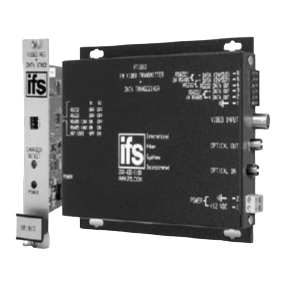
- Page 1 VR1910 VT1910 VR1910-R3 VT1910-R3 VR1910WDM VT1910WDM VR1910WDM-R3 VT1910WDM-R3 VR1920 VT1920 VR1920-R3 VT1920-R3 VR1930WDM VT1930WDM VR1930WDM-R3 VT1930WDM-R3 IFS Fiber Module Installation & Operation Instructions P/N 1062800 • REV B • ISS 01JUL11...
- Page 2 VT/VR1900 Tamper Switch RS232 DATA Data Input Data Output Ground Tamper Switch - Data Input RS422 DATA +Data Input - Data Output +Data Output Tamper Switch 2-WIRE - Data Input/ Output +Data Input/ Output RS485 DATA Tamper Switch - Data Input 4-WIRE +Data Input RS485 DATA...
- Page 3 VT1910 TAMPER SWITCH FM VIDEO TRANSMITTER RS422/ DATA TRANSCEIVER - DATA (IN/OUT) - 6 2W RS485 Video source + DATA (IN/OUT) - 5 RS232 RS232 DATA OUT - 4 - DATA OUT - 3 RS422/ 4W RS485 + DATA OUT - 2 OFF = TAMPER SW ON = BYPASS TAMPER SW...
- Page 4 VT1900 A Power LED illuminates NOTE: WITHOUT PROPER FIBER CONNECTION, LED's DO NOT INDICATE CORRECT OPERATIONAL STATUS OF THE UNIT. VR1900 A Carrier Detect LED illuminates Power RS232 RS422 RS485 RS485 NOT USED 2-WIRE 4-WIRE...
-
Page 5: Fcc Compliance
FCC Compliance This device complies with Part 15 of the FCC Rules. Operation is subject to the following two conditions: (1) This device may not cause harmful interference, and (2) this device must accept any interference received, including interference that may cause undesirable operation. Changes or modifications not expressly approved by International Fiber Systems, Inc. - Page 6 Contacting us For help installing, operating, maintaining, and troubleshooting this product, refer to this document and any other documentation provided. If you still have questions, contact us during business hours (Monday through Friday, excluding holidays, between 5 a.m. and 5 p.m. Pacific Time). Sales and support contact information North Toll-free: 855.286.8889 in the US, including Alaska and Hawaii;...
- Page 7 Product Disassembly Instructions for WEEE Per European Directive 2002/95/EC Waste Electrical and Electronic Equipment Required Tools: One number 2 Phillips (crosstip) screwdriver. One number 2 flat screwdriver. For the enclosed box version: 1. Locate and remove box cover securement screws. Usually, but not limited to, at least 4 screws.
- Page 8 Copyright © 2011 UTC Fire & Security. All rights reserved. Trademarks and Interlogix and IFS names and logos are trademarks of patents UTC Fire & Security. Other trade names used in this document may be trademarks or registered trademarks of the manufacturers or vendors of the respective products.
Need help?
Do you have a question about the Interlogix VR1910 and is the answer not in the manual?
Questions and answers