
Related Manuals for ICP DAS USA iCAM-771


Summary of Contents for ICP DAS USA iCAM-771
- Page 1 5MP + 360/180° Panoramic View IR Fisheye Network Camera User’s Manual Version 1.0...
- Page 2 Warranty All products manufactured by ICP DAS are under warranty regarding defective materials for a period of one year, starting from the date of delivery to the original purchaser. Warning ICP DAS CO., LTD. assumes no liability for damages consequent to the use of this product.
-
Page 3: Table Of Contents
IP Filter Tab ....................51 4.2.5 WISE Tab ....................52 4.3 Video & Audio Setup ....................53 4.3.1 Video Tab ..................... 54 4.3.2 Stream Tab ....................62 4.3.3 Audio Tab ....................65 4.3.4 Privacy Mask Tab ..................66 iCAM-771 User’s Manual ICP DAS... - Page 4 Playback Tab ....................85 4.6 Remote Storage Setup ....................86 4.6.1 Remote Storage Tab ..................86 5 Appendix 5.1 Firmware Upgrade and Trouble Shooting ..............87 5.2 How to let camera to do Hardware Reset ..............97 iCAM-771 User’s Manual ICP DAS...
- Page 5 3. Add Section 4.3.5 WISE Tab for communicating the camera with the WISE controller to perform a WISE Surveillance Solution. 4. For Chapter 3, modify the “Live View” button related descriptions. 5. For Chapter 1 to 5, modify its description for more detail and clear. iCAM-771 User’s Manual ICP DAS...
-
Page 6: Read Me First
Read Me First! Important Notes This User Manual is intended for administrators and users of the iCAM-771 IR Fisheye Type Network Dome Camera, including instructions for using and managing the camera on your network. The use of surveillance devices may be prohibited by law in your country or area. It is therefore the user’s responsibility to ensure that the operation of such devices is legal before... -
Page 7: Introduction
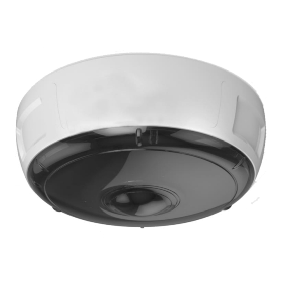
Chapter 1 1 Introduction iCAM-771 is Intelligent IR Fisheye Network Dome Camera featured with 5 Mega Pixel resolution; also this model has superior H.264-AVC performance and rich functions. iCAM-771 includes fisheye lens for 360° panoramic wide angle view without blind spot and built-in IR to effectively see 10 meters distance. With WDR enhancement, you could view in extremely bright or dark environments. -
Page 8: Hardware Overview
I/O Port DC Jack ※ Please note that RJ45 network cable has to plug to the PoE Port cable that with LED indicator , connect to incorrect one may damage camera hardware. 8 Introduction iCAM-771 User’s Manual ICP DAS... -
Page 9: Specifications
3 simultaneous streams at Normal Mode S/N Ratio Above 39 dB Dynamic Range 67 dB Adjustable resolution, quality and bit rate Video Streaming ROI (Region of Interest) Provide for 5 Independent Streams 9 Introduction iCAM-771 User’s Manual ICP DAS... - Page 10 Digital output x1 Video output Default Setting LED Indicator System power and status indicator IEEE 802.3af PoE Power Input DC 12V Power Consumption Max. 10W (IR ON) Dimensions Ø :150 x 58mm 10 Introduction iCAM-771 User’s Manual ICP DAS...
- Page 11 Operating Temperature 0°C ~ 50°C Operating Humidity 10% ~ 80% System Requirements Operating System Microsoft Windows 10/8/Vista/XP Mozilla Firefox 7 ~ 52, Web Browser Internet Explorer 7 ~ 11 Other Players VLC: 1.1.11 or above 11 Introduction iCAM-771 User’s Manual ICP DAS...
-
Page 12: Installation And Setup
1. Extract the round mounting plate from the camera enclosure by pressing then turning it counterclockwise. 2. Attach the provided alignment sticker to the ceiling / wall where the camera is going to be installed. Installation and Setup 12 iCAM-771 User’s Manual ICP DAS... - Page 13 4. After screwing the mounting plate on the wall, drill a hole as indicate on the sticker. Gently get the cable to go through the hole before installing the camera. 13 Installation and Setup iCAM-771 User’s Manual ICP DAS...
- Page 14 After that, the camera will be securely fastened. 6. Installation completed. 5~6 meters high would have better visual effect; Would prevent light halo caused by different directions reflected light. 14 Installation and Setup iCAM-771 User’s Manual ICP DAS...
-
Page 15: Install Microsd Card
Chapter 2 2.2 Install microSD Card The iCAM-771 built-in microSD card slot supports microSDHC / microSDXC 64 GB or above for local storage application. The user can prepare a microSD card to install into the camera via the following steps. -
Page 16: Connecting Camera To Network
FINDER), or directly set up the camera via the Microsoft IE browser using the following default IP information: IP: 192.168.255.2 (Default Username/Password: admin/admin) Submask: 255.255.0.0 Gateway address: 192.168.0.1 DNS Server address: 8.8.8.8 16 Installation and Setup iCAM-771 User’s Manual ICP DAS... -
Page 17: Configuring Camera Via Cam Finder
In order to connect to the Web-based user interface of the camera, the host PC must be in the same subnet. For more information about subnets, please consult your network administrator. 17 Installation and Setup iCAM-771 User’s Manual ICP DAS... - Page 18 If want to change the software language, please click the right key of mouse on the gray area and select the [Language] to choose one language from the [Traditional Chinese], [English], [Spanish] and [Simplified Chinese]. 18 Installation and Setup iCAM-771 User’s Manual ICP DAS...
-
Page 19: Use Cam Finder To Assign Ip Address
Click the [Device Search] to search the camera on the network. Under your selected item, double-click the left Mouse button or Right-click the Mouse button to open the Property Page of the [Single Device Setting]. 19 Installation and Setup iCAM-771 User’s Manual ICP DAS... - Page 20 Chapter 2 Check [Static IP address] item to select the network connection method of the camera. After modifying the camera properties, click [Set] button to save and enable the configuration modifications. 20 Installation and Setup iCAM-771 User’s Manual ICP DAS...
- Page 21 Use “Ctrl” or “Shift” key on 5. This Utility can batch modify IP address automatically. the keyboard to choose several Camera Devices. Then click the [Batch Device Setting] to configure them together. 21 Installation and Setup iCAM-771 User’s Manual ICP DAS...
-
Page 22: Open The Web-Based Ui Of The Camera
For the first time login of setting or using, please use the admin admin default username , password NOTE: Use of Microsoft IE browser is recommended as it offers a better compatibility. 22 Installation and Setup iCAM-771 User’s Manual ICP DAS... - Page 23 Besides, use of Microsoft IE browser is recommended as it offers a better compatibility. Please click the NetcamViewer hyper-link to download and install it. NOTE: Please also note to close all browser applications before NetcamViewer web component installation. 23 Installation and Setup iCAM-771 User’s Manual ICP DAS...
- Page 24 1. From the IE Browser menu, select [Internet Options] -> [Security] -> [Custom Level] 2. Set the security level to Low and click [OK]. 3. Don’t forget to restore the security level after the ActiveX installation. 24 Installation and Setup iCAM-771 User’s Manual ICP DAS...
-
Page 25: Live View Ui Settings
You may enter “admin” for both. Click OK button when completed. (Note that same Browser with different version or different vendor Browser will behave different dialog window. Below picture is belonging to IE Browser’s diagram.) Camera Live View UI Settings 25 iCAM-771 User’s Manual ICP DAS... - Page 26 3) The “Live View Setting” window will then display offering all the necessary set up tools for changing the live view reconfigurations. The functions of each of these tools are explained in the following sections. Camera Live View UI Settings 26 iCAM-771 User’s Manual ICP DAS...
-
Page 27: Quick Access Buttons
“ESC” key on the keyboard could exit full screen view. Camera Live View UI Settings 27 iCAM-771 User’s Manual ICP DAS... -
Page 28: Camera Live View Ui Setting Tools
Select the default language of the user-interface. Setup button: Click Setup button can change or update more Camera settings, including Video & Audio, System, Network, Event, Local Storage and Remote Storage. Camera Live View UI Settings 28 iCAM-771 User’s Manual ICP DAS... - Page 29 Original (360 degree Full Panorama View) Quad View Double-Broad View (180 degree Ultra Wide Angle View x 2) Triple View (180 degree Ultra Wide Angle View + Twin PTZ View) Camera Live View UI Settings 29 iCAM-771 User’s Manual ICP DAS...
- Page 30 In the meanwhile, you could also see region’s amplification effect displayed real time in the lower-left, upper-right or lower-right Live View Window. Camera Live View UI Settings 30 iCAM-771 User’s Manual ICP DAS...
- Page 31 H.264/MPEG4 streaming is available. Video Stream: Two kinds of resolutions are available to let user choose; check higher or lower streaming would be suitable for user’s network environment. Camera Live View UI Settings 31 iCAM-771 User’s Manual ICP DAS...
- Page 32 Home button. You can also directly click the mouse button on the video to drag for pan and tilt, roll the mouse wheel for zoom a selected area. Camera Live View UI Settings 32 iCAM-771 User’s Manual ICP DAS...
- Page 33 Zoom Button: Click button to zoom-in and button to zoom-out the selected scene. Zoom setting is saved with the selected pre-defined point of view area. Camera Live View UI Settings 33 iCAM-771 User’s Manual ICP DAS...
- Page 34 & time for each saved snapshot file as “night456 _20170510_102808.jpg”. To start capturing snapshots, click the Snapshot button in the Quick Access Button area. Language : Setting Language: Select the default language of the user-interface. Camera Live View UI Settings 34 iCAM-771 User’s Manual ICP DAS...
- Page 35 This can be accomplished by clicking the Setup button (indicated in the above figure). The Setup dialog (see following figure) will then display to provide the range of setup categories you will be able to change. Camera Live View UI Settings 35 iCAM-771 User’s Manual ICP DAS...
-
Page 36: Setup
Chapter 4 4 Setup NOTE For “Live View” setup execution, please refer to the previous chapter “Live View UI Settings” Setup 36 iCAM-760D User’s Manual ICP DAS... -
Page 37: System Setup
Chapter 4 System Setup Clicking the System button will display the following tabbed panes relative to system configurations. Setup 37 iCAM-760D User’s Manual ICP DAS... -
Page 38: Information Tab
Chapter 4 4.1.1 Information Tab The Information tabbed pane provides the existing system status of the Camera which includes Model Name, System Time, Firmware Version, MAC Address, ActiveX Control Version, Wired Network, Wireless Network and DDNS Server Status. Setup 38 iCAM-760D User’s Manual ICP DAS... -
Page 39: Time Tab
Chapter 4 4.1.2 Time Tab The Time tabbed pane is where you set up the clock of your Camera to synchronize with your local time. Where: System Time: The Network Camera current date and time is applied and displayed here based on the setup status of the System Time Settings as detailed below. - Page 40 Chapter 4 Set Manually: Synchronize with the computer Time: Select this option to manually synchronize the Network Camera clock (date and time) with that of the local host computer. Assign value: Select this option to enter the date and time manually. Enable Daylight Saving: Select this option only when applicable at your location.
-
Page 41: Security Tab
Chapter 4 4.1.3 Security Tab The Security tabbed pane allows you to add new Camera User Name and change Password and the surveillance status or User Group. Where: User List: This is a permanent default setting and cannot be removed nor changed. - Page 42 Chapter 4 User Name: Enter the new user name to be added into the list (see Note 4 of dialog for proper entry). Password: Enter the new password (see Note 4 of dialog for proper entry). Confirm password: Enter the password again for authentication (encoded display).
-
Page 43: Maintenance Tab
Chapter 4 4.1.4 Maintenance Tab Download and save the latest firmware in the PC. Click here to browse and select it. The Maintenance tabbed pane allows you to upgrade the firmware with the latest version and to restore the Network Camera settings to factory default. Setup ... - Page 44 Chapter 4 ※ Please specify the correct firmware version mapped with your camera to upgrade, or there will be danger to damage camera system. Remote/Local Upgrade Firmware: Recommend to use the local upgrade. Download the latest firmware file from the website. Follow the steps: 1) Click the Browse button to access and select the appropriate...
-
Page 45: System Log Tab
Chapter 4 4.1.5 System Log Tab The System Log tabbed pane allows you to see Camera’s basic log on another browser page or Remote Log Server. Where: Click “Logs” and then there will be another browser Logs: page opening and then displaying Camera’s basic log lists. -
Page 46: Network Setup
Chapter 4 Network Setup Clicking the Network button will display the following tabbed panes on configuring Camera connection with the network. Setup 46 iCAM-760D User’s Manual ICP DAS... -
Page 47: General Tab
Chapter 4 4.2.1 General Tab The General tabbed pane (shown above) allows you to redefine the network and port protocol settings of the Network Camera. Where: Network Settings: DHCP: This option obtains the available dynamic IP address assigned by the DHCP server each time the Camera is connected to the network. - Page 48 Chapter 4 PPPoE: Select this option to set PPPoE account & password. While PPPoE protocol is selected, you may have to enter some more information such as the above picture. While Camera IP is changed dynamically because of PPPoE Network Connection, its new IP Address will be sent to “Sender E-mail Address”...
-
Page 49: Ddns Tab
Chapter 4 4.2.2 DDNS Tab The DDNS tabbed pane allows you to configure the Dynamic Domain Name System of your network device with a host name instead of the IP Address. Where: DDNS Enable: Enable the check box to support DDNS function. Host Name: Enter the Host name which you registered and got through DNS Service Provider. -
Page 50: Multicast Tab
Chapter 4 4.2.3 Multicast Tab The Multicast tabbed pane allows you to open Camera’s UDP Multicast Streaming function. By default, Camera’s live stream belongs to RTSP Protocol. It means camera has to send an individual streaming for each client wish to see the videos. So the more the client number is, the larger the network bandwidth required and the bigger loading of the camera. -
Page 51: Ip Filter Tab
Chapter 4 4.2.4 IP Filter Tab The IP Filter tabbed pane could let you configure device IP list which is denied access to this camera. Where: Click the Add button to show the IP address input field. Start IP address: Fill in the first address of IP range which you would like to deny its access to camera. -
Page 52: Wise Tab
Chapter 4 4.2.5 WISE Tab The WISE tabbed pane allows you to communicate the iCAM camera with WISE controller to perform a WISE surveillance system. ICP DAS WISE surveillance solution integrates logic control, I/O, camera and data log in one single WISE controller. WISE allows two-way interactions between the I/O and the camera;... -
Page 53: Video & Audio Setup
Chapter 4 Video & Audio Setup Clicking the Video & Audio button will display tabbed panes for defining Camera video, streaming, and audio functions. Setup 53 iCAM-760D User’s Manual ICP DAS... -
Page 54: Video Tab
Chapter 4 4.3.1 Video Tab Setup 54 iCAM-760D User’s Manual ICP DAS... - Page 55 Chapter 4 The Video tabbed pane lets you to perform live adjustments and improvement of the Camera captured video effect relative to the target environment. Where: Video Settings: There are “Day” and “Night” 2 lens modes. Day/Night Mode: Brightness: The luminance of the captured image apart from its hue or saturation.
- Page 56 Chapter 4 Contrast: The brightness ratio of the lightest to the darkest part of the video image. Try to assign the fit value according to the environment. Adjust the Contrast value to 100. Sharpness: Sharpness can be defined as edge contrast. So when we increase sharpness, we increase the contrast only along/near edges.
- Page 57 Chapter 4 Exposure Level: It is used to control Exposure Target; and its behavior determined by Aperture and Shutter Speed. So, if you leave the Shutter open longer, you're getting more light to the sensor, and the picture gets brighter; if Exposure is shortened (provide less light to the sensor), the picture gets darker.
- Page 58 Chapter 4 EV Compensation: Exposure Compensation is a feature of a camera that allows you to adjust the exposure value manually. You may increase or decrease the amount of brightness or darkness of your picture through sliding the bar. Try to assign the fit value according to the environment.
- Page 59 Chapter 4 Wide Dynamic Range: Enable this function could let camera provide clear images even under backlighting. Set WDR function to Disable. Set WDR function to Enable. Set WDR function to Disable. Set WDR function to Enable. Also provide strength to let user set according to the environment. Set strength to 1 (by default) Set strength to 100 Set strength to 200...
- Page 60 Chapter 4 Source View Video Orientation: In order to fulfill different camera install location, four kinds video orientation are provided. ※ Please also note video would rotate source view orientation first and then change to different display mode if user set in camera configuration. Such as, Setup ...
- Page 61 Chapter 4 Below there are Advanced Settings adjustments, you could set image parameters of Fisheye Lens. Advanced Settings: Day/Night Threshold: Set the illumination lux value (5 ~ 100) to auto-trigger the Camera into “day” or “night” mode relative to luminance of the area under surveillance.
-
Page 62: Stream Tab
Chapter 4 4.3.2 Stream Tab NOTE If the “Event Alarm Setting” (see Section 4.4.2 & 4.4.3) is enabled, an alert message will display requiring you to disable the feature first before proceeding to change the Streaming settings. Otherwise, adjustments to video quality streaming settings cannot be accomplished. Setup ... - Page 63 Chapter 4 The Stream tabbed pane provides the adjustments for the video quality of the Camera streaming function. The setting items on this pane are as follows: Video quality settings for stream #: Stream 1 is the primary quality setting for live view streaming.
- Page 64 Chapter 4 Text Overlay: When enabled, each streamed frame will be overlaid with the Camera ID (text field, Chinese word isn’t support) and stamped with date/time (if enabled) as illustrated below. RTSP Port Access Name: When RTSP or VLC media-player is used, the port can be renamed with easy to remember pathname.
-
Page 65: Audio Tab
Chapter 4 4.3.3 Audio Tab The Audio tabbed pane provides the following audio adjustments to your Camera microphone and speaker: Type: Select which kind of codec you would like to set as Audio-In signal output format. Enable or disable mute function of the Camera’s Audio-In signal. Mute: Gain +20dB: Enable or disable Gain +20dB function of the Camera Audio-In... -
Page 66: Privacy Mask Tab
Chapter 4 4.3.4 Privacy Mask Tab 3) Enable the check box. This is a “Line” type. 2) Lay out masking This is an “Ellipse” screens on the type. areas to be blocked from surveillance. 1) Select a masking shape to block the private area you wish to obstruct from... - Page 67 Chapter 4 3) Once the masking screen is acceptable, click the Enable Privacy Mask check box. If the laid out screen needs correction, click Delete button and redo the masking screen lay out process. 4) Click the Save button. This will turn the laid out screen into solid block. ...
-
Page 68: Fisheye Settings Tab
Chapter 4 4.3.5 Fisheye Settings Tab The Fisheye Setting tabbed pane allows you to set video modes captured by fisheye lens: Full-image: Means video pass through lens to sensor directly, without crop. In this mode, 2592x1944@10fps is supported maximally. Circular fisheye: Means video would be dewrap by Hardware Fisheye Correction Processor;... -
Page 69: Event Setup
Clicking the Event button will display the tabbed panes (see figure below) for defining event recording of the Camera. The iCAM-771 is equipped with a card slot for microSD / microSDHC / microSDXC 64GB memory card. This storage card is utilized to store recording of local video and still JPEG images taken in response to set events. -
Page 70: Motion Tab
Chapter 4 4.4.1 Motion Tab From the Motion tabbed pane, you can define specific target areas within the scope of surveillance to focus the motion detection function. 1. To enable “Motion Detection” function. 2. To draw a region to define the detection range. - Page 71 Chapter 4 3) To assign unique names to each framed location for easy identification, click on the frame and a Window Name text box with the default name of the selected frame, will appear at the bottom of the pane (see figure below). Enter a new name and click the Save button.
-
Page 72: Video Tab
Chapter 4 4.4.2 Video Tab The Video tabbed pane sets the video recording trigger method, the four methods available for selection are Schedule, Period, Motion is detected by the Camera, and GPIO Input, each of which can be set up with user scheduled recoding time and duration, as well as defining the video record file target destination. - Page 73 Chapter 4 Period: This method will trigger the Camera video surveillance/recording operation for a defined Time Lapse (in seconds) whenever motion is detected. The video record may be stored in the SD card, Remote Disk, provided to host by E-mail/FTP as selected or through all of them.
- Page 74 Chapter 4 Motion: This method will trigger the Camera video surveillance/recording operation whenever motion is detected within the defined days of the week and at the time of the set days. Each recording time-span is in accordance with the total value of Pre-event recording and Post event recording (in seconds).
- Page 75 Chapter 4 GPIO Input: On the defined days of the week and at certain time of the set days, the Camera will be triggered by its GPIO Input Signal when its state changes. (As for the more GPIO Signal setting, you may refer to 4.4.4 GPIO Tab).
- Page 76 Chapter 4 E-mail Settings: As for the settings of SMTP Service, kindly please contact with your E-mail service provider. After you confirm all parameters are correct and working properly, you may enter them into the text area manually. FTP Settings: As for the settings of FTP Service, kindly please contact with your FTP service provider.
-
Page 77: Snapshot Tab
Chapter 4 4.4.3 Snapshot Tab The Snapshot tabbed pane sets the Camera to take snapshot images when event is triggered. The four methods available for selection are Always, Schedule, Motion, and GPIO Input, each of which can be set up with user scheduled time and capture interval, as well as defining the snapshot file target destination. - Page 78 Chapter 4 Schedule: This method activates the Camera snapshot operation continuously when the defined days of the week and set time of the set days are met. The Camera will continuously capture snapshots of the area under surveillance at every 1, 2 or 3 seconds intervals.
- Page 79 Chapter 4 Motion: This method will trigger the Camera snapshot operation according to the set time interval (in seconds) whenever motion is detected within the defined days of the week and at the time of the set days. Single or 6 snapshots may be captured as defined. The stream of accumulated snapshots may be stored in the SD Card, Remote Disk, sent to host by E-mail、FTP, activated GPIO Output Port as preferred or through all of them.
- Page 80 Chapter 4 GPIO Input: This method will trigger the Camera snapshot operation according to the set time interval (in seconds) whenever GPIO Input Signal is detected within the defined days of the week and at the time of the set days. (As for the more GPIO Signal Settings, you may refer to 4.4.4 GPIO Tab)
- Page 81 Chapter 4 E-mail Settings: As for the settings of SMTP Service, kindly please contact with your E-mail service provider. After you confirm all parameters are correct and working properly, you may enter them into the text area manually. FTP Settings: As for the settings of FTP Service, kindly please contact with your FTP service provider.
-
Page 82: Gpio Tab
Chapter 4 4.4.4 GPIO Tab The GPIO tabbed pane allows you to set GPIO Input Signal condition. GPIO Input: The Trigger Pattern can decide which kind of pattern would trigger event successfully (Low to High, High to Low or State change). -
Page 83: Local Storage Setup
Chapter 4 Local Storage Setup Clicking the Local Storage button will display the following tabbed panes to provide information on existing local storage, such as disk size info, type, and status. If recording is in progress when clicking the Local Storage button, a warning message will occur. -
Page 84: Local Storage Tab
Chapter 4 4.5.1 Local Storage Tab The Local Storage tabbed pane displays the SD card status. It shows the SD card total capacity (Total size), available memory (Free size), used memory (Used size) and used memory ratio (Use(%)). It also display the current Camera operation condition (Recording status) and provide “SD card control”... -
Page 85: Playback Tab
Chapter 4 4.5.2 Playback Tab The Playback tabbed pane allows user to playback video and snapshot files stored in the SD memory card. These files were saved using the Event setup for video (see Section 4.4.2) and snapshots (Section 4.4.3) with the SD card check box enabled. Playback of the stored videos or snapshots is performed from files recorded on particular date range as explained in the following figure. -
Page 86: Remote Storage Setup
Chapter 4 Remote Storage Setup Clicking the Remote Storage button will display the following tabbed panes to provide information of Remote Disk. 4.6.1 Remote Storage Tab The Remote Storage tabbed pane displays the Remote Disk information of NFS/SMBFS Server. It shows the total capacity (Total size), available memory (Free size), used memory (Used size) and used memory ratio (Use(%)) of server disk. -
Page 87: Appendix
Please help to check if your IE Browser version is 11 first. If it is yes, please kindly refer to the below steps to enable Compatible View settings of IE 11 Browser. Appendix 87 iCAM-771 User’s Manual ICP DAS... - Page 88 Chapter 5 Find Tools icon and then select Compatibility View settings. Appendix 88 iCAM-771 User’s Manual ICP DAS...
- Page 89 Chapter 5 Click button to add camera webpage as a compatible website. After successful adding, camera webpage should be set as compatible view website. Appendix 89 iCAM-771 User’s Manual ICP DAS...
- Page 90 Then camera webpage would be refreshing real-time and starting to load camera webpage. button to enable NetcamViewer component running… Click Allow Manual enter camera’s username/password to pass authentication. Camera live stream is successful playing in IE11 Browser Appendix 90 iCAM-771 User’s Manual ICP DAS...
- Page 91 NetcamViewer installation again. So before NetcamViewer installation, please make sure there’s no “iexplore” process running in Windows Task Manager Window. If there is “iexplore” process existing, select “End Process” to force its stop. Appendix 91 iCAM-771 User’s Manual ICP DAS...
- Page 92 This will mainly remind you to close all running browser applications and then press “OK” button to continue NetcamViewer installation. Or these two windows will pop continuously until all browsers are closed. Appendix 92 iCAM-771 User’s Manual ICP DAS...
- Page 93 Manual input username and password of the camera to pass login authentication of camera webpage. (Default username and password are admin and admin.) After Live View page is entering successfully, find the “SETUP” button. Clicking it could change or update more Camera settings. Appendix 93 iCAM-771 User’s Manual ICP DAS...
- Page 94 After downloading it, click the Browse button to open the file open dialog for firmware choosing. Download and save the latest firmware in the PC Click here to browse and select it. Appendix 94 iCAM-771 User’s Manual ICP DAS...
- Page 95 Camera Webpage is reloading, it means all processes of camera are stopping at the same time. After all processes are stopped, the camera will start to upgrade the firmware you chose. Appendix 95 iCAM-771 User’s Manual ICP DAS...
- Page 96 After camera Web-based UI is re-login successfully, go to Information Tab of Camera Setup Webpage to check if the firmware version is different with before; or check if the firmware version is the same with distributor/dealer provided. Appendix 96 iCAM-771 User’s Manual ICP DAS...
-
Page 97: How To Let Camera To Do Hardware Reset
Setting(5) and GND(4) pins to short, remove the connection 10 seconds later. PoE Port Cable (Power of Ethernet, RJ45) I/O Port Cable (RJ45) DC Jack RJ45 Pin Table of I/O Port Cable: Appendix 97 iCAM-771 User’s Manual ICP DAS... - Page 98 3) While RJ45 Green LED Indicator of the PoE Port Cable is flashing quickly, means camera Hardware Reset Loading is processing now…… Please don’t power off camera or do any unnecessary jobs during this 3 minutes interval time; camera would reboot and continue streaming automatically. Appendix 98 iCAM-771 User’s Manual ICP DAS...