Advertisement
I N S T A L L A T I O N I N S T R U C T I O N S
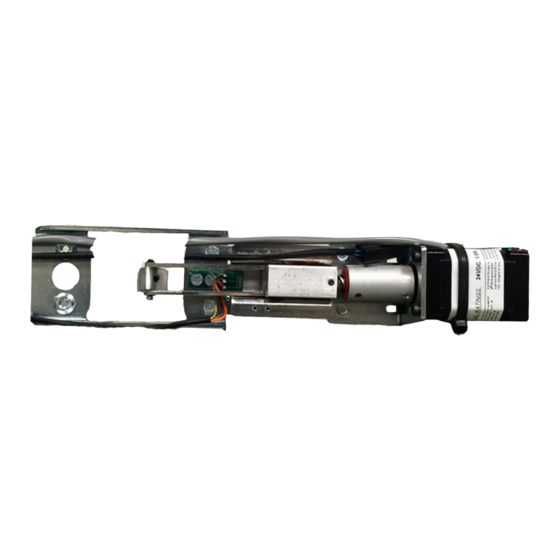
The Command Access SLP-UL-M-KIT is a field installable motorized latch-pullback kit for the
A.
B.
K it I n cl ud e s
A.
1- Motor Mount Assembly w/ MM4S series module
B.
2 -Phillips Screws
C.
1 - Push & Go Connector
D.
1- MM4S switch program sticker
E.
1 - 5/64" Hex Wrench
F.
1 - 5/32" Drill Bit
G.
1 - 8' Lead w/ VD Connector
U.S. Customer Support
1-888-622-2377
SLP-UL-M-KIT
Sargent 80 series.
C.
D.
Scan or Click here
Installation Video
Visit our website for more details
www.CommandAccess.com
E.
E.
F.
Tools R eq ui red
•
Power Drill
G.
Canada Customer Support
1-855-823-3002
Doc # 20094_E
Advertisement
Table of Contents

Related Manuals for Command access SLP-UL-M-KIT


Summary of Contents for Command access SLP-UL-M-KIT
- Page 1 I N S T A L L A T I O N I N S T R U C T I O N S The Command Access SLP-UL-M-KIT is a field installable motorized latch-pullback kit for the Sargent 80 series.
- Page 2 T E C H N I C A L I N F O R M A T I O N pecificationS MM4 S witcheS • Input Voltage: 24VDC +/- 10% witch rogram • Wire gauge: Minimum 18 gauge Low Torque Low Torque Mode Standard Torque •...
- Page 3 HARDWARE Module Legend Standard Placement ecommenDeD ower upplieS All Command Access exit devices & field installable kits have been thoroughly cycle tested with Command Access power supplies at our factory. For more information click here or go to our website...
- Page 4 STEP 1 - Disassemble Exit Device A. Remove End Cap & Filler Plate B. Remove (4) screws from baserail C. Partially slide push pad off approx. 2-3” D. Using 5/32” drill bit. Open up the (2) back screw holes #3 & 4.
- Page 5 E. Continue sliding push pad half way out of the base rail so activating bracket is accessible. Next, remove metal rod and AB mount can be put aside. Baserail AB Mount Metal Rod STEP 2 - Install Motor Mount A. Attach the link assembly to the end of the activating bracket. Next, place activating bracket into center of the motor mount.
- Page 6 STEP 3 - Install MM3 & Reassemble Device A. Slide push pad with motor kit back into the device. Also, the filler plate must be slid in at same time. B. Make sure Latch retractor is pressed down so push pad slides over it. C.
Need help?
Do you have a question about the SLP-UL-M-KIT and is the answer not in the manual?
Questions and answers