Table of Contents
Advertisement
Quick Links
Advertisement
Table of Contents

Subscribe to Our Youtube Channel
Related Manuals for Advantech PCIE-1758 Series


Summary of Contents for Advantech PCIE-1758 Series
- Page 1 User Manual PCIE-1758 Series 128-Channel Isolated Digital I/O Card...
- Page 2 No part of this manual may be reproduced, copied, translated, or transmitted in any form or by any means without the prior written permission of Advantech Co., Ltd. The information provided in this manual is intended to be accurate and reliable.
- Page 3 This product has passed the CE test for environmental specifications when shielded cables are used for external wiring. We recommend the use of shielded cables. This type of cable is available from Advantech. Please contact your local supplier for ordering information.
- Page 4 PC is powered on. Disconnect the power before implementing any configuration changes. A sud- den rush of power after connecting a jumper or installing a card may damage sensitive electronic components. PCIE-1758 Series User Manual...
-
Page 5: Table Of Contents
Specifications ........21 Isolated Digital Input (PCIE-1758DI & PCIE-1758DIO)......22 Digital Filter Time (PCIE-1758DI & PCIE-1758DIO) ....... 22 Isolated Digital Output (PCIE-1758DO & PCIE-1758DIO) ...... 22 General ....................23 Power Consumption................23 Appendix B Block Diagrams .........25 PCIE-1758 Series User Manual... - Page 6 Block Diagrams..................26 PCIE-1758 Series User Manual...
- Page 7 Chapter Introduction This chapter introduces the PCIE- 1758 series cards and their typical applications. Features Applications Installation Guide Software Overview Device Driver Roadmap Accessories...
-
Page 8: Chapter 1 Introduction
2,500 VDC, preventing your host system from harm. Wide Input Range The PCIE-1758 series accepts a wide range of input voltage, from 10 to 30 V , and it is suitable for most industrial applications with 12 V and 24 V input voltage. -
Page 9: Applications
Board ID Setting The PCIE-1758 series has a built-in DIP switch that defines each card’s ID when mul- tiple cards have been installed in the same PC chassis. The board ID setting function is very useful when users build systems with multiple PCIE-1758 series cards. With correct Board ID settings, you can easily identify and access each card during hard- ware configuration and software programming. -
Page 10: Software Overview
Software Overview Advantech offers a comprehensive set of DLL drivers and third-party driver support and application software to fully exploit the functions of PCIE-1758 series cards. These include DAQNavi software LabView driver Advantech DAQ tools Programming DA&C Cards Advantech application software, such as Advantech DAQNavi software can be used for programming PCIE-1758 series cards. -
Page 11: Programming With Daqnavi Device Drivers Function Library
These accessories include Wiring Cables PCL-101100S-1E, PCL-101100S-2E, PCL-101100S-3E PCL-101100S is a 100-pin mini-SCSI shielded cable especially designed for PCIE-1758 series cards. This cable should be used with an ADAM-39100 wiring board. Wiring Boards ADAM-39100-BE ADAM-39100 is a 100-pin SCSI wiring terminal module with DIN-rail mount. - Page 12 PCIE-1758 Series User Manual...
-
Page 13: Chapter 2 Installation
Chapter Installation This chapter details the packing list, unpacking instructions, and driver and card installation proce- dures. Unpacking Driver Installation Hardware Installation... -
Page 14: Unpacking
Unpacking Upon receiving your PCIE-1758 series product, check that the package contains the following items: 1 x PCIE-1758 series DAQ card 1 x PCIE-1758 series user manual PCIE-1758 series cards feature certain electronic components that are vulnerable to electrostatic discharge (ESD). -
Page 15: Hardware Installation
Touch a metal surface of the computer to neutralize any static electricity that may be in your body. Insert the PCIE-1758 series card into a PCI Express slot. Hold the card by its edges only and carefully align it with the slot. Push the card firmly to insert the card in the slot. - Page 16 PCIE-1758 Series User Manual...
-
Page 17: Chapter 3 Signal Connections
Chapter Signal Connections This chapter explains how to con- nect input and output signals to PCIE-1758 series cards via the I/O connector. Overview Card Layout Switch and Jumper Settings Signal Connections Field Wiring Considerations... -
Page 18: Overview
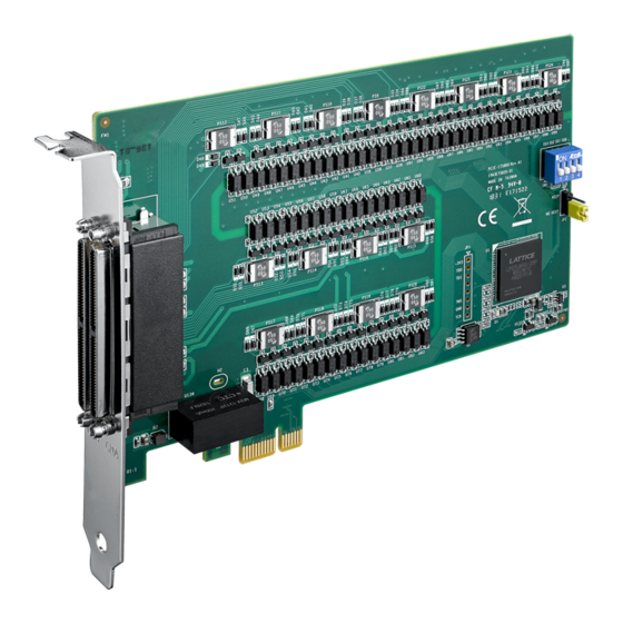
PC and other hardware devices. This chapter provides useful information about how to connect input and output signals to PCIE-1758 series cards via the I/O connector. Card Layout Figures 3.1 to 3.3 show the connector, jumper, and switch locations on PCIE-1758 series cards. -
Page 19: Switch And Jumper Settings
3.3.1 Board ID (SW1) PCIE-1758 series cards feature a built-in DIP switch (SW1) that is used to define each card’s board ID. When multiple cards are installed on the same chassis, the board ID switch is useful for identifying each card’s device number. After installing each card, users can differentiate them using their board ID. -
Page 20: Power On Configuration (Jp2)
3.3.2 Power On Configuration (JP2) The default status of the PCIE-1758 series cards' digital output after a system power on is OPEN to protect external devices from damage. JP2 determines whether the last output value is retained after a hot system reset. Table 3.2 shows the jumper positions for power on configuration. - Page 21 Figure 3.4 PCIE-1758DIO I/O Connector Pin Assignments PCIE-1758 Series User Manual...
- Page 22 Figure 3.5 PCIE-1758DI I/O Connector Pin Assignments PCIE-1758 Series User Manual...
- Page 23 Figure 3.6 PCIE-1758DO I/O Connector Pin Assignments PCIE-1758 Series User Manual...
-
Page 24: I/O Connector Pin Definition
Free wheeling common diode for isolated digital output of port A & port B PCD_PCOM Free wheeling common diode for isolated digital output of port C & port D PEF_PCOM Free wheeling common diode for isolated digital output of port E & port F Isolated ground PCIE-1758 Series User Manual... -
Page 25: Isolated Digital Input
This means users can apply positive or negative voltage to an isolated input pin ). Every 16 input channels share one common pin. Figure 3.7 shows how to con- nect an external input source to one of the card’s isolated input channels. Figure 3.7 Isolated Digital Input Connection PCIE-1758 Series User Manual... -
Page 26: Isolated Digital Output
Figure 3.8 Isolated Digital Output Connection Field Wiring Considerations When using PCIE-1758 series cards to acquire data from an outdoor environment, noises in the environment can significantly affect the accuracy of measurements if due cautions are not taken. The following measures can help reduce possible inter- ference on signal wires connecting signal sources to the PCIE-1758 series card. -
Page 27: Appendix A Specifications
Appendix Specifications... -
Page 28: Isolated Digital Input (Pcie-1758Di & Pcie-1758Dio)
Isolated Digital Output (PCIE-1758DO & PCIE- 1758DIO) PCIE-1758DO: 128 Number of Output Channels PCIE-1758DIO: 64 2500 V Optical Isolation Opto-Isolator Response Time 100 µs 5 ~ 40 V Supply Voltage 350mA max./channel @25 °C Sink Current 250mA max./channel @60 °C PCIE-1758 Series User Manual... -
Page 29: General
3.3 V@ 250mA Typical 12 V @ 20mA 12 V @ 30mA 12 V @ 25mA 3.3 V@ 425mA 3.3 V@ 400mA 3.3 V@ 450mA Max. 12 V @ 250mA 12 V @ 260mA 12 V @ 235mA PCIE-1758 Series User Manual... - Page 30 PCIE-1758 Series User Manual...
-
Page 31: Appendix B Block Diagrams
Appendix Block Diagrams... - Page 32 Block Diagrams PCIE-1758DIO PCIE-1758DI PCIE-1758 Series User Manual...
- Page 33 PCIE-1758DO PCIE-1758 Series User Manual...
- Page 34 PCIE-1758 Series User Manual...
- Page 35 PCIE-1758 Series User Manual...
- Page 36 No part of this publication may be reproduced in any form or by any means, such as electronically, by photocopying, recording, or otherwise, without prior written permission from the publisher. All brand and product names are trademarks or registered trademarks of their respective companies. © Advantech Co., Ltd. 2019...
Need help?
Do you have a question about the PCIE-1758 Series and is the answer not in the manual?
Questions and answers