Table of Contents
Advertisement
Quick Links
Advertisement
Table of Contents

Related Manuals for Advantech PCIE-1763AH


Summary of Contents for Advantech PCIE-1763AH
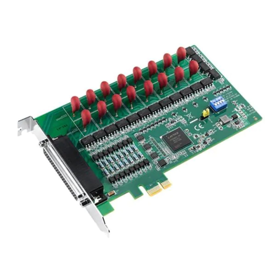
- Page 1 User Manual PCIE-1763AH 16-ch Solid-State Relay Output (AC) and 16-ch Isolated Digital Input w/ Digital Filter & Interrupt PCIe Card PCIE-1763DH 16-ch Solid-State Relay Output (DC) and 16-ch Isolated Digital Input w/ Digital Filter & Interrupt PCIe Card...
- Page 2 No part of this manual may be reproduced, copied, translated, or transmitted in any form or by any means without the prior written permission of Advantech Co., Ltd. The information provided in this manual is intended to be accurate and reliable.
- Page 3 CE-compliant industrial enclosure prod- ucts. Technical Support and Assistance Visit the Advantech website at www.advantech.com/support to obtain the latest product information. Contact your distributor, sales representative, or Advantech's customer service center for technical support if you need additional assistance. Please have the following information ready before calling: –...
- Page 4 In accordance with IEC 704-1:1982 specifications, the sound pressure level at the operator’s position does not exceed 70 dB (A). DISCLAIMER: These instructions are provided according to IEC 704-1 standards. Advantech disclaims all responsibility for the accuracy of any statements contained herein. PCIE-1763AH/DH User Manual...
-
Page 5: Table Of Contents
......11 Overview ....................12 Isolated Digital Input Connections............12 Figure 3.1 Isolated Digital Input Connections ......12 Relay Connections .................. 13 Figure 3.2 PCIE-1763AH Relay Output Connections ....13 Figure 3.3 PCIE-1763DH Relay Output Connections....13 Appendix A Specifications ........15 Isolated Digital Inputs................ - Page 6 PCIE-1763AH/DH User Manual...
-
Page 7: Chapter 1 Overview
Chapter Overview... -
Page 8: Introduction
Introduction The PCIE-1763AH provides 16 solid-state relay (SSR) outputs and 16 isolated digital inputs. The SSRs are classified to semiconductor relays which do not have moving contact and differ from the conventional electro-mechanical relays in many ways. They are superior to electro-mechanical relays in longer lifetime, higher operating speed, less contact problems such as arcs, bounce, and noise. -
Page 9: Applications
Before installing the PCIE-1763 card, please ensure that you have the following nec- essary components: PCIE-1763 card PCIE-1763 user manual Driver software - Advantech DLL drivers (can be downloaded from the Advan- tech product page) Wiring cable - PCL-10162 (optional) Wiring board - ADAM-3962 (optional) ... -
Page 10: Software Overview
“twisted-pair cable”, reducing cross-talk and noise from other signal sources. Further- more, the analog and digital lines are separately sheathed and shielded to avoid EMI/ EMC problems. Advantech provides 1 m and 3 m cables to satisfy various usage requirements. -
Page 11: Chapter 2 Installation
Chapter Installation... -
Page 12: Unpacking
The PCIE-1763 card is equipped with one function switch and one jumper settings. Information regarding how to configure the card is provided below. Additionally, Fig- ure 2.1 shows the connector, jumper, switch locations to enable users to identify card components. Figure 2.1 Card Connector, Jumper, and Switch Locations PCIE-1763AH/DH User Manual... - Page 13 0. If you need to adjust it to another value, please refer to Table 2.2 for set- ting SW1. Table 2.2: Board ID Settings (SW1) Position 1 Position 2 Position 3 Position 4 Board ID *The default setting is 0 PCIE-1763AH/DH User Manual...
-
Page 14: Pin Assignments
Normally Open pin of relay output 8 COM 8 Common pin of relay output 8 NO 9 Normally Open pin of relay output 9 COM 9 Common pin of relay output 9 NO 10 Normally Open pin of relay output 10 PCIE-1763AH/DH User Manual... - Page 15 COM 14 Common pin of relay output 14 NO 15 Normally Open pin of relay output 15 COM 15 Common pin of relay output 15 Other 9,30,31, No Connection 32,51,52 Figure 2.2 I/O Connector Pin Assignments for PCIE-1763 PCIE-1763AH/DH User Manual...
- Page 16 PCIE-1763AH/DH User Manual...
-
Page 17: Chapter 3 Signal Connections
Chapter Signal Connections... -
Page 18: Overview
This means users can apply positive or negative voltage to an isolated input pin (V ). The figure below shows how to connect an external input source to one of the card’s isolated input channels. Figure 3.1 Isolated Digital Input Connections PCIE-1763AH/DH User Manual... -
Page 19: Relay Connections
Relay Connections After power on, the initial relay output status of the PCIE-1763 card should be as shown in Figure 3.2 and 3.3 below Figure 3.2 PCIE-1763AH Relay Output Connections Figure 3.3 PCIE-1763DH Relay Output Connections PCIE-1763AH/DH User Manual... - Page 20 PCIE-1763AH/DH User Manual...
-
Page 21: Appendix A Specifications
Appendix Specifications... -
Page 22: Isolated Digital Inputs
Critical rate of rise of off-state voltage 200 V/μs min. Holding current 25 mA max. Zero crossing voltage 50 V max. Operate time 1/2 cycle of load power source + 100 μs max. Release time Isolation protection 2,500 Vrms PCIE-1763AH/DH User Manual... -
Page 23: General Specifications
+3.3 V @ 300 mA (typical) Power Consumption +3.3 V @ 500 mA (max.) Operating 0 ~ 60 °C (32 ~ 140 °F) Temperature Storage -20 ~ 70 °C (-4 ~ 158 °F) Relative Humidity 10 - 95% RH non-condensing Certifications CE/FCC PCIE-1763AH/DH User Manual... - Page 24 PCIE-1763AH/DH User Manual...
-
Page 25: Appendix B Block Diagram
Appendix Block Diagram... -
Page 26: Block Diagram
Block Diagram Appendix PCIE-1763AH/DH User Manual... - Page 27 PCIE-1763AH/DH User Manual...
- Page 28 No part of this publication may be reproduced in any form or by any means, such as electronically, by photocopying, recording, or otherwise, without prior written permission from the publisher. All brand and product names are trademarks or registered trademarks of their respective companies. © Advantech Co., Ltd. 2020...
Need help?
Do you have a question about the PCIE-1763AH and is the answer not in the manual?
Questions and answers