Table of Contents
Advertisement
Quick Links
Advertisement
Table of Contents

Related Manuals for Advantech PCIE-1754


Summary of Contents for Advantech PCIE-1754
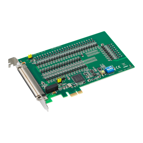
- Page 1 PCIE-1754 64-ch Isolated Digital Input PCI Express Card User Manual...
- Page 2 No part of this man- ual may be reproduced, copied, translated or transmitted in any form or by any means without the prior written permission of Advantech Co., Ltd. Information provided in this manual is intended to be accurate and reli- able.
- Page 3 Product Warranty (2 years) Advantech warrants to you, the original purchaser, that each of its prod- ucts will be free from defects in materials and workmanship for two years from the date of purchase. This warranty does not apply to any products which have been repaired or...
- Page 4 This product has passed the CE test for environmental specifications when shielded cables are used for external wiring. We recommend the use of shielded cables. This kind of cable is available from Advantech. Please contact your local supplier for ordering information.
- Page 5 Before setting up the system, check that the items listed below are included and in good condition. If any item does not accord with the table, please contact your dealer immediately. • PCIE-1754 DA&C Card • StartUp or User Manual • Companion DVD-ROM with DAQNavi drivers included...
- Page 6 PCIE-1754 User Manual...
-
Page 7: Table Of Contents
Figure 2.2:DAQNavi Installation Setup Screen ..12 Hardware Installation ............13 Device Setup & Configuration ........14 Figure 2.3:The Device Setting of PCIE-1754 ....14 Figure 2.4:The Digital I/O Setting Page ...... 15 Figure 2.5:The Device Testing of PCIE-1754 ..... 16 Chapter 3 Signal Connections ........ - Page 8 PCIE-1754 User Manual viii...
- Page 9 Introduction This chapter introduces the PCIE-1754 cards and their typical applications. Sections include: • Features • Applications • Installation Guide • Software Overview • Device Driver Roadmap • Accessories...
-
Page 10: Chapter 1 Introduction
, preventing your host system from any incidental harms. Wide Input Range The PCIE-1754 has a wide range of input voltage from 10 to 30 V , and it is suitable for most industrial applications with 12 V and 24 V input voltage. -
Page 11: Applications
Board ID Setting The PCIE-1754 has a built-in DIP switch that helps define each card’s ID when multiple cards have been installed on the same PC chassis. The board ID setting function is very useful when users build their system with multiple PCIE-1754 cards. -
Page 12: Figure 1.1:Installation Flow Chart
DA&C card, you can then begin the Installa- tion procedures. Figure 1-1 on the next page provides a concise flow chart to give users a broad picture of the software and hardware installation procedures: Figure 1.1: Installation Flow Chart PCIE-1754 User Manual... -
Page 13: Software Overview
1.4 Software Overview Advantech offers a rich set of DLL drivers, third-party driver support and application software to help fully exploit the functions of your PCIE-1754 card: • DAQNavi software (on the companion DVD-ROM) • LabView driver • Advantech DAQ tools Programming choices for DA&C cards... -
Page 14: Daqnavi Device Driver Programming Roadmap
• Borland Delphi For instructions on how to begin programming works in each develop- ment tool, Advantech offers Tutorial Chapter in the DAQNavi SDK Man- ual for your reference. Please refer to the corresponding sections in this chapter on the DAQNavi SDK Manual to begin your programming efforts. -
Page 15: Accessories
PCIE-1754 card. These accessories include: Wiring Cables PCL-10250 The PCL-10250 is a 100-pin SCSI to two 50-pin SCSI shielded cable that specially designed for PCIE-1754 card. It should be used with ADAM-3951 wiring board. PCL-101100M The PCL-101100M cable is a 100pin SCSI shielded cable. - Page 16 PCIE-1754 User Manual...
- Page 17 Installation This chapter provides a packaged item checklist, proper instructions for unpacking and step-by-step procedures for both driver and card installation. Sections include: • Unpacking • Driver Installation • Hardware Installation • Device Setup & Configuration...
-
Page 18: Chapter 2 Installation
Chapter 2 Installation 2.1 Unpacking After receiving your PCIE-1754 package, please inspect its contents first. The package should contain the following items: • PCIE-1754 DA&C Card • StartUp or User Manual • Companion DVD-ROM with DAQNavi drivers included. The PCIE-1754cards harbor certain electronic components vulnerable to electrostatic discharge (ESD). -
Page 19: Driver Installation
2.2 Driver Installation We recommend you install the driver before you install the PCIE-1754 card into your system, since this will guarantee a smooth installation pro- cess. The Advantech DAQNavi Device Drivers Setup program for the PCIE- 1754 card is included in the companion DVD-ROM that is shipped with your DA&C card package. -
Page 20: Figure 2.2:Daqnavi Installation Setup Screen
Select the PCIE series and the specific device then follow the installation instructions step by step to complete your device driver installation and setup. Back and select the DAQNavi SDK to install the Advantech Navi- gator. Figure 2.2: DAQNavi Installation Setup Screen... -
Page 21: Hardware Installation
Installation) After the Device Drivers installation is completed you can install the PCIE-1754 card into any PCI Express slot on your computer. However, it is suggested that you refer to the computer’s user manual or related docu- mentation if you have any doubts. Please follow the steps below to install the card onto your system. -
Page 22: Device Setup & Configuration
2.4 Device Setup & Configuration The Advantech Navigator program is a utility that allows you to setup, configure and test your device, and later stores your settings on the sys- tem registry. These settings will be used when you call the APIs of DAQNavi device drivers. -
Page 23: Figure 2.4:The Digital I/O Setting
Configuring the Device Please go to the Digital Input/Output page to configure your device. Here you can set the DI interrupt trigger edge of PCIE-1754. Figure 2.4: The Digital I/O Setting Page Chapter 2... -
Page 24: Figure 2.5:The Device Testing Of Pcie-1754
Device Test page to test your hardware by using the testing util- ity supplied. Figure 2.5: The Device Testing of PCIE-1754 For more detailed information, please refer to the DAQNavi SDK Manual or the User Interface Manual in the Advantech Navigator. PCIE-1754 User Manual... - Page 25 Signal Connections This chapter provides useful informa- tion about how to connect input signals to the PCIE-1754 cards via the I/O con- nector. Sections include: • Overview • Switch and Jumper Settings • Signal Connections • Field Wiring Considerations...
-
Page 26: Chapter 3 Signal Connections
PCIE-1754 cards via the I/O connector. 3.2 Switch and Jumper Settings Please refer to Figure 3.1 for jumper and switch locations on PCIE-1754. Figure 3.1: Connector and Switch Locations PCIE-1754 User Manual... -
Page 27: Board Id (Sw1)
3.2.1 Board ID (SW1) The PCIE-1754 have a built-in DIP switch (SW1), which is used to define each card’s board ID. When there are multiple cards on the same chassis, this board ID switch is useful for identifying each card’s device number. -
Page 28: Signal Connections
3.3 Signal Connections Pin Assignment The I/O connector on the PCIE-1754 is a 100-pin connector that enable you to connect to accessories with the PCL-10250 or PCL-101100M shielded cable. Figure 3.2 shows the pin assignments for the 100-pin I/O connector on the PCIE-1754, and Table 3.4 shows its I/O connector signal description. -
Page 29: I/O Connector Pin Definition
*Note: The PCL-10250 shielded cable is especially designed for the PCIE-1754 to reduce noise in the signal lines. Please refer to Appendix C for the pin assignment of connecting PCL-10250 and ADAM-3951. 3.3.1 I/O Connector Pin Definition Table 3.2: I/O Connector Signal Descriptions... -
Page 30: Isolated Digital Input
Figure 3.3: Isolated Digital Input Connection 3.4 Field Wiring Considerations When you use PCIE-1754 cards to acquire data from outside, noises in the environment might significantly affect the accuracy of your measure- ments if due cautions are not taken. The following measures will be help- ful to reduce possible interference running signal wires between signal sources and the PCIE-1754 card. - Page 31 • If you have to place your signal cable parallel to a power line that has a high voltage or high current running through it, try to keep a safe dis- tance between them. Alternatively, you can place the signal cable at a right angle to the power line to minimize the undesirable effect.
- Page 32 PCIE-1754 User Manual...
- Page 33 Specifications...
-
Page 34: Appendix A Specifications
Appendix A Specifications A.1 Isolated Digital Input Input Channels Input Voltage Logic 0: 3 V max. Logic 1: 10 V min. (30 V max.) Input Current 10 V @ 2.97 mA 20 V @ 6.35 mA 30 V @ 9.73 mA Interrupt Capable Ch. - Page 35 Block Diagrams...
-
Page 36: Appendix B Block Diagrams
Appendix B Block Diagrams PCIE-1754User Manual... - Page 37 ADAM-3951 Pin Assignment...
-
Page 38: Figure C.1:Connect To Pcl-10250 Con1
Appendix C ADAM-3951 Pin Assignment Please refer to Figure C.1 and Figure C.2 for the pin assignments if you select Advantech ADAM-3951 as your wiring board for connecting to PCL-10250 and PCIE-1754. Figure C.1: Connect to PCL-10250 CON1 PCIE-1754 User Manual... -
Page 39: Figure C.2:Connect To Pcl-10250 Con2
Figure C.2: Connect to PCL-10250 CON2 Appendix C... - Page 40 PCIE-1754 User Manual...
Need help?
Do you have a question about the PCIE-1754 and is the answer not in the manual?
Questions and answers