Table of Contents
Advertisement
Quick Links
Advertisement
Table of Contents

Related Manuals for Advantech PCIE-1824


Summary of Contents for Advantech PCIE-1824
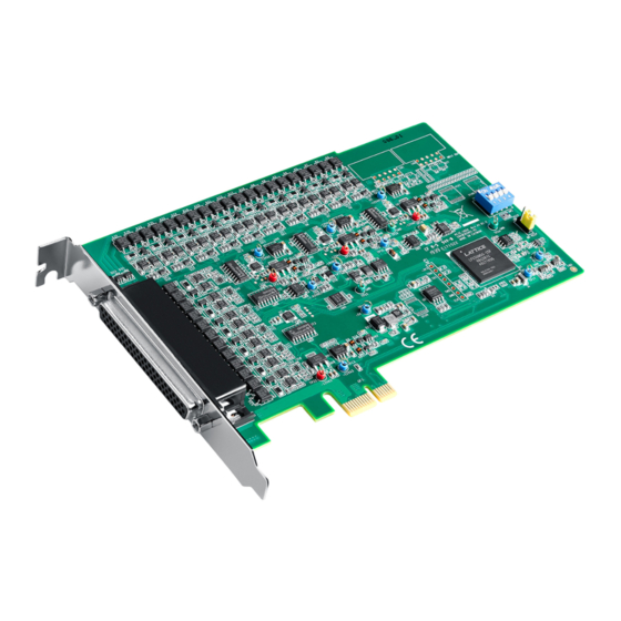
- Page 1 User Manual PCIE-1824/1824L 16-bit, 32/16-ch Analog Output PCI Express Card...
- Page 2 Because of Advantech’s high quality-control standards and rigorous testing, most of our customers never need to use our repair service. If an Advantech product is defec- tive, it will be repaired or replaced at no charge during the warranty period. For out- of-warranty repairs, you will be billed according to the cost of replacement materials, service time and freight.
- Page 3 This product has passed the CE test for environmental specifications when shielded cables are used for external wiring. We recommend the use of shielded cables. This kind of cable is available from Advantech. Please contact your local supplier for ordering information.
- Page 4 PCIE-1824 User Manual...
-
Page 5: Table Of Contents
Unpacking ....................8 Driver Installation ..................9 Hardware Installation ................9 Device Setup & Configuration ..............10 Figure 2.1 PCIE-1824 Device Settings ........10 Figure 2.2 The Device Setting Page.......... 11 Figure 2.3 PCIE-1824 Device Testing ........11 Chapter Signal Connections ......13... - Page 6 PCIE-1824 User Manual...
-
Page 7: Chapter 1 Introduction
Chapter Introduction This chapter introduces PCIE- 1824 and its typical applications. Sections include: Features Applications Installation Guide Software Overview Roadmap Accessories... -
Page 8: Features
PCIE-1824 is a high-density multiple channel analog card for the PCIE bus, where each analog output channel is equipped with a 16-bit DAC. It features optional volt- ages, current output and a Board ID switch. PCIE-1824 is an ideal solution for indus- trial applications where multiple analog output channels are required. - Page 9 Figure 1.1 on the next page provides a concise flow chart to give you a broad picture of the software and hardware installation procedures: PCIE-1824 User Manual...
- Page 10 Figure 1.1 Installation Flow Chart PCIE-1824 User Manual...
-
Page 11: Software Overview
Advantech Navigator. Programming with DAQNavi Device Drivers Function Library Advantech DAQNavi Device Drivers offer a rich function library that can be utilized in various application programs. This function library consists of numerous APIs that PCIE-1824 User Manual... -
Page 12: Accessories
Drivers error, you can pass the error, you can check the error code and error descrip- tion within the Error Control of each function in the DAQNavi SDK Manual. Accessories Advantech offers a complete set of accessory products to support the PCIE-1824 card. These accessories include: Wiring Cables ... -
Page 13: Chapter 2 Installation
Chapter Installation This chapter provides a packing item checklist, proper instructions for unpacking, and step-by-step procedures for both driver and card installation. Sections include: Unpacking Driver Installation Hardware Installation Device Setup & Configuration... -
Page 14: Unpacking
Unpacking After receiving your PCIE-1824 package, inspect the contents. The package should include the following items: PCIE-1824 card Startup Manual The PCIE-1824 card has certain electronic components vulnerable to electrostatic discharge (ESD). ESD can easily damage the integrated circuits and certain compo- nents if preventive measures are ignored. -
Page 15: Driver Installation
Touch the metal part on the surface of your computer to neutralize any static electricity that might be on your body. Insert the PCIE-1824 card into the PCI Express interface. Hold the card only by its edges and carefully align it with the slot. Insert the card firmly into place. Use of excessive force must be avoided;... -
Page 16: Device Setup & Configuration
Device Setup & Configuration The Advantech Navigator program is a utility that allows you to set up, configure and test your device, and later stores your settings on the system registry. These settings will be used when you call the APIs of Advantech Device Drivers. Take the following PCIE-1824 details as an example. - Page 17 After your card is properly installed and configured, you can go to the Device Test page to test the hardware using the testing utility supplied. Figure 2.3 PCIE-1824 Device Testing For more detailed information, please refer to the DAQNavi SDK Manual or the User Interface Manual in the Advantech Navigator.
- Page 18 PCIE-1824 User Manual...
-
Page 19: Chapter 3 Signal Connections
Chapter Signal Connections This chapter provides useful information about how to connect input and output signals to the PCIE-1824 card via the I/O con- nector. Sections include: Overview Board ID Settings Signal Connections Field Wiring Considerations... -
Page 20: Overview
This chapter provides useful information about how to connect input and output signals to the PCIE-1824 card via the I/O connector. Switch and Jumper Settings Please refer to Figure 3.1 for jumper and switch locations on PCIE-1824. Figure 3.1 Connector and Switch Locations PCIE-1824 User Manual... -
Page 21: Board Id (Sw1)
3.2.1 Board ID (SW1) The PCIE-1824 has a built-in DIP switch (SW1), which is used to define each card’s board ID. When there are multiple cards on the same chassis, this board ID switch is used to set each card’s device number. -
Page 22: Signal Connections
Signal Connections Pin Assignments The I/O connector on the PCIE-1824 is a 62-pin connector that enables you to con- nect to accessories with the PCL-10162 shielded cable. Figure 3.2 shows the pin assignments for the 62-pin I/O connector on the PCIE-1824, and Table 3.3 shows its I/O connector signal description. -
Page 23: I/O Connector Signal Description
Analog output channel 30 AO31 Analog output channel 31 Power and Ground +12V +12 V power supply for external use +5 V power supply for external use 43 ~ 63 Ground Others 2 ~ 5, 23 ~ 26 No connect. PCIE-1824 User Manual... -
Page 24: Analog Output Connections
3.3.2 Analog Output Connections The PCIE-1824 provides 32 channels of analog output (AO) signal generation with output ranges of ±10 V, 0 ~ 20 mA, and 4 ~ 20 mA. The output range of each channel can be configured independently by software. -
Page 25: Field Wiring Considerations
If the cable needs to unavoidably go through an area with significant electromagnetic interference, a shielded cable with twisted-pair wires should be used. Try to place the cable at a right angle to the nearby power lines to minimize any undesirable effects. PCIE-1824 User Manual... - Page 26 PCIE-1824 User Manual...
-
Page 27: Appendix A Specifications
Appendix Specifications... -
Page 28: Function Block
Operating temperature within 5 °C of last auto-calibration temperature < ±0.01% Over full operating temperature range < ±0.03% Offset error Operating temperature within 5 °C of last auto-calibration temperature < ±1 mV Over full operating temperature range < ±3 mV PCIE-1824 User Manual... -
Page 29: Current Output Accuracy
3.3 V @ 350 mA, 12 V @ 350 mA Power Consumption Max. 3.3 V @ 370 mA, 12 V @ 1000 mA Operating 0~60°C (32~140°F) Temperature Storage -40 ~ 70°C (-40 ~ 158°F) Operating 10~90%RH non-condensing Relative Humidity Storage 5~95%RH non-condensing Certifications CE/FCC certified PCIE-1824 User Manual... - Page 30 No part of this publication may be reproduced in any form or by any means, electronic, photocopying, recording or otherwise, without prior written permis- sion of the publisher. All brand and product names are trademarks or registered trademarks of their respective companies. © Advantech Co., Ltd. 2019...
Need help?
Do you have a question about the PCIE-1824 and is the answer not in the manual?
Questions and answers