Table of Contents
Advertisement
Quick Links
Advertisement
Table of Contents

Related Manuals for Advantech PCIE-1765


Summary of Contents for Advantech PCIE-1765
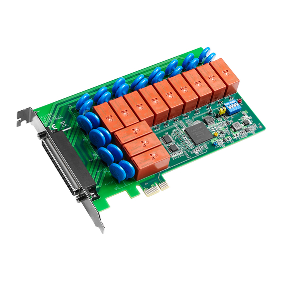
- Page 1 User Manual PCIE-1765 12-Channel Relay PCI Express Card...
- Page 2 The documentation and the software included with this product are copyrighted 2018 by Advantech Co., Ltd. All rights are reserved. Advantech Co., Ltd. reserves the right to improve the products described in this manual at any time without notice. No part of this manual may be reproduced, copied, translated, or transmitted in any form or by any means without the prior written permission of Advantech Co., Ltd.
-
Page 3: Declaration Of Conformity
CE-compliant industrial enclosure prod- ucts. Technical Support and Assistance Visit the Advantech website at www.advantech.com/support to obtain the latest product information. Contact your distributor, sales representative, or Advantech's customer service center for technical support if you need additional assistance. Please have the following information ready before calling: –... -
Page 4: Safety Instructions
In accordance with the IEC 704-1:1982 standards, the sound pressure level at the operator’s position does not exceed 70 dB (A). These instructions are provided according to IEC 704-1. Advantech disclaims all responsibility for the accuracy of any statements contained herein. -
Page 5: Table Of Contents
Signal Connections ......11 Overview ....................12 Relay Connections .................. 12 Figure 3.1 Relay output connection ........... 12 Appendix A Specifications ........13 Relay Output ................... 14 General Specifications ................14 Appendix B Block Diagram ........15 Block Diagram..................16 PCIE-1765 User Manual... - Page 6 PCIE-1765 User Manual...
-
Page 7: Chapter 1 Overview
Chapter Overview... -
Page 8: Introduction
Introduction Advantech’s PCIE-1765 is a 12-channel relay actuator card for PCIE bus. Built with 12 onboard SPDT relays, the PCIE-1765 card is ideal for applications such as device ON/OFF control and power switching. Moreover, to ensure easy monitoring, each relay is equipped with a red LED indicator to show its ON/OFF status. -
Page 9: Installation Guide
PCIE-1765 card. Software Overview Advantech offers a wide range of DLL drivers, application software, and third-party driver support to assist you with fully exploiting the functions of the PCIE-1765 card. DLL driver (Download from the product page) ... -
Page 10: Accessories
Wiring Cable The PCL-10137 shielded cable is especially designed to provide high resistance to noise for PCIE-1765 cards. To achieve superior signal quality, the signal wires are twisted to form a “twisted-pair cable”, reducing cross-talk and noise from other signal sources. -
Page 11: Chapter 2 Installation
Chapter Installation... -
Page 12: Unpacking
PCIE bus or to clear relays only as part of a system bootup. The PCIE-1765 card satisfies both of these needs with the provision of jumper JP2. Depending on the application, this may allow relay outputs to be configured as “OFF”... - Page 13 Board ID (SW1) The PCIE-1765 card features a built-in DIP switch (SW1) that is used to define the board ID for each card. When multiple cards are installed on the same chassis, the board ID switch is useful for identifying each card’s device number. After installing PCIE-1765 cards, users can identify each card using their different device numbers.
-
Page 14: I/O Connectors
I/O Connectors Pin Assignments The pin assignments for the 37-pin I/O connector on the PCIE-1765 card are shown in Figure 2.2. -NOn (n = 0 ~ 11): Normally open pin of the relay output -COMn (n = 0 ~ 11):... -
Page 15: Device Setup And Configuration
After which, the device settings are stored on the system registry and used when Advantech device driver APIs are employed. Setting Up the Device To install the I/O device for the PCIE-1765 card, run the Advantech Device Man- ager program (accessible via Start/Programs/Advantech Automation/Device Manager/Advantech Device Manager). - Page 16 PCIE-1765 User Manual...
-
Page 17: Chapter 3 Signal Connections
Chapter Signal Connections... -
Page 18: Overview
A good signal connection can prevent unnecessary and costly damage to your PC and other hardware devices. Relay Connections After system power on, the initial relay output status of the PCIE-1765 card should be as shown below: Figure 3.1 Relay output connection... -
Page 19: Appendix A Specifications
Appendix Specifications... -
Page 20: Relay Output
Power Consumption +3.3V @ 2500mA (max.) Operating: 0 ~ 60 °C (32 ~ 140 °F) Temperature Storage: -40 ~ 70 °C(-40 ~ 158 °F) Relative Humidity 5 ~ 95% RH non-condensing (refer to IEC 68-2-3) Certifications CE, FCC PCIE-1765 User Manual... -
Page 21: Appendix B Block Diagram
Appendix Block Diagram... -
Page 22: Block Diagram
Block Diagram Appendix PCIE-1765 User Manual... - Page 23 PCIE-1765 User Manual...
- Page 24 No part of this publication may be reproduced in any form or by any means, such as electronically, by photocopying, recording, or otherwise, without prior written permission from the publisher. All brand and product names are trademarks or registered trademarks of their respective companies. © Advantech Co., Ltd. 2018...
Need help?
Do you have a question about the PCIE-1765 and is the answer not in the manual?
Questions and answers