Table of Contents
Advertisement
Quick Links
Advertisement
Table of Contents

Related Manuals for Advantech PCIE-1753


Summary of Contents for Advantech PCIE-1753
- Page 1 User Manual PCIE-1753 96-ch Digital I/O PCI Express Card...
- Page 2 No part of this manual may be reproduced, copied, translated or transmitted in any form or by any means without the prior written permission of Advantech Co., Ltd. Information provided in this manual is intended to be accurate and reliable. How- ever, Advantech Co., Ltd.
-
Page 3: Declaration Of Conformity
This product has passed the CE test for environmental specifications when shielded cables are used for external wiring. We recommend the use of shielded cables. This kind of cable is available from Advantech. Please contact your local supplier for ordering information. -
Page 4: Safety Instructions
Warnings, Cautions and Notes Warning! Warnings indicate conditions, which if not observed, can cause personal injury! Caution! Cautions are included to help you avoid damaging hardware or losing data. e.g. There is a danger of a new battery exploding if it is incorrectly installed. Do not attempt to recharge, force open, or heat the battery. - Page 5 The sound pressure level at the operator's position according to IEC 704-1:1982 is no more than 70 dB (A). Safety Precaution - Static Electricity DISCLAIMER: This set of instructions is given according to IEC 704-1. Advantech disclaims all responsibility for the accuracy of any statements contained herein.Safety Precaution - Static Electricity Follow these simple precautions to protect yourself from harm and the products from damage.
- Page 6 PCIE-1753User Manual...
-
Page 7: Table Of Contents
Table 3.2: Board ID setting (SW1)..........11 Table 3.3: Summary of Jumper Settings ........12 Signal Connections ................. 13 Appendix A Specifications ........15 Specifications ..................16 A.1.1 PCIE-1753 .................. 16 Appendix B Block Diagram ........17 PCIE-1753....................18 PCIE-1753 User Manual... - Page 8 PCIE-1753 User Manual viii...
-
Page 9: Chapter 1 Overview
Chapter Overview... -
Page 10: Introduction
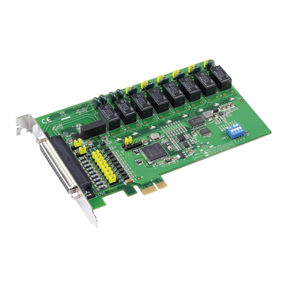
Introduction The PCIE-1753 is a 96-ch DI/O card with PCI Express bus. It provides 96 channel of parallel digital input/output compatible with 5V/TTL. It emulates mode 0 of the 8255 PPI chip, but the buffered circuits offer a higher driving capability than the 8255. -
Page 11: Applications
Digital Filter for Digital Input Channels The PCIE-1753 includes a programmable digital filter on channel 0 (bit 0) on each port to eliminate the unexpected signal or noise from the card's inputs. When the dig- ital filter is enabled, the state of the corresponding input channel will not update immediately until the signal is stable for a period of time which is programmed by the user. -
Page 12: Accessories
Accessories Advantech offers a complete set of accessory products to support the PCIE-1753 card. These accessories include: Wiring Cable The PCL-10268 shielded cable is specially designed for PCIE-1753 cards to provide high resistance to noise. To achieve better signal quality, the signal wires are twisted in such a way as to form a “twisted-pair cable”, reducing cross-talk and noise from... -
Page 13: Chapter 2 Hardware Installation
Chapter Hardware Installation... -
Page 14: Installation
This chapter gives users a package item checklist, proper instructions about unpack- ing and step-by-step procedures for both driver and card installation. Unpacking After receiving your PCIE-1753 package, please inspect its contents first. The pack- age should contain the following items: ... -
Page 15: Driver Installation
Make sure you have installed the driver first before you install the card. After the device driver installation is completed, you can now go on to install the PCIE-1753 card in any PCI Express slot on your computer. Follow the steps below to install the card on your system. -
Page 16: Figure 2.1 Device Manager
After the PCIE-1753 card is installed, you can verify whether it is properly installed on your system through the Device Manager: 1. Access the Device Manager through Control Panel/System/Device Manager. 2. The device name of the PCIE-1753 should be listed on the Device Manager tab as follows. Figure 2.1 Device Manager... -
Page 17: Chapter 3 Signal Connections
Chapter Signal Connections... -
Page 18: Overview
PC and other hardware devices. This chapter provides useful information about how to connect input and output signals to the PCIE-1753 via the I/O connector. Switch and Jumper Settings Figure 3.1 Card Connector, Jumper and Switches... -
Page 19: Jumper Jp1 Restores Ports To Their Condition Prior To Reset
Jumper JP1 gives the PCIE-1753 a new and valuable function. With JP1 enabled, the PCIE-1753 “memorizes” all port I/O settings and output values, and, in the event of a “hot” reset, the settings and output values present at the port just prior to reset are restored to each port following reset. -
Page 20: Table 3.3: Summary Of Jumper Settings
Set bit 4, 5, 6, 7 of port n as software-configurable input or out- put (default) Set bit 0, 1, 2, 3 of port n as output port Set bit 4, 5, 6, 7 of port n as output port PCIE-1753 User Manual... -
Page 21: Signal Connections
Signal Connections PCIE-1753 Pin Assignments Name Pin Description P0_0-7 I/O pins of Port 0 P1_0-7 I/O pins of Port 1 P2_0-7 I/O pins of Port 2 P3_0-7 I/O pins of Port 3 P4_0-7 I/O pins of Port 4 P5_0-7 I/O pins of Port 5... - Page 22 TTL Digital Input/Output The PCIE-1753 has 96 TTL-level digital inputs and outputs. The following figure shows connections to exchange digital signals with other TTL devices: If you want to receive an OPEN/SHORT signal from a switch or relay. See the figure...
- Page 23 Appendix Specifications...
-
Page 24: Appendix A Specifications
167.7 mm x 100 mm (6.6" x 3.9") Power Consumption Typical: 3.3V @ 1 A Maximum: 3.3 V @ 3 A 12 V @ 0.25 A Operating Temperature 0~60°C (32~140°F) Storage Temperature -25~85°C (-4~185°F) Storage Humidity 5~95%RH,non-condensing (refer to IEC 68-2-3) PCIE-1753 User Manual... -
Page 25: Appendix B Block Diagram
Appendix Block Diagram... -
Page 26: Pcie-1753
PCIE-1753 PCIE-1753 User Manual... - Page 27 PCIE-1753 User Manual...
- Page 28 No part of this publication may be reproduced in any form or by any means, electronic, photocopying, recording or otherwise, without prior written permis- sion of the publisher. All brand and product names are trademarks or registered trademarks of their respective companies. © Advantech Co., Ltd. 2013...
Need help?
Do you have a question about the PCIE-1753 and is the answer not in the manual?
Questions and answers