Advertisement
Quick Links
Installation Manual
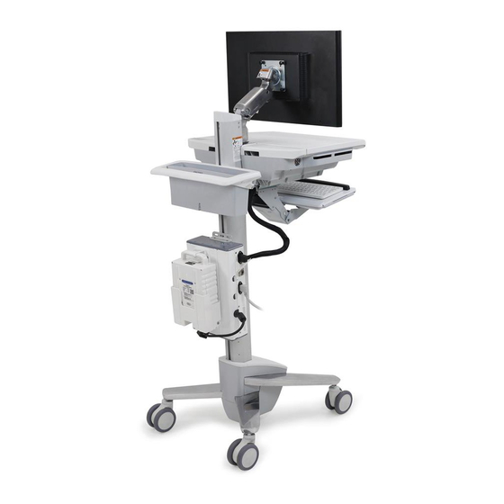
StyleView LiFe Power Upgrade System
330Wh LiFe battery
The StyleView LiFe Power Upgrade System is intended to provide AC power to
support AC powered computer equipment.
This installation manual is only for installation onto an Ergotron cart. For power
system information, please see provided operations manual.
For the latest User Installation Guide please visit: www.ergotron.com
User's Guide - English
Guía del usuario - Español
Manuel de l'utilisateur - Français
Gebruikersgids - Nederlands
Benutzerhandbuch - Deutsch
Guida per l'utente - Italiano
Användarhandbok - svenska
ユーザーガイ ド : 日本語
用户指南 : 汉语
888-83-072-G-01 rev. D• 01/15
1 of 17
Advertisement

Subscribe to Our Youtube Channel
Related Manuals for Ergotron StyleView LiFe Power Upgrade System


Summary of Contents for Ergotron StyleView LiFe Power Upgrade System
- Page 1 Installation Manual StyleView LiFe Power Upgrade System 330Wh LiFe battery The StyleView LiFe Power Upgrade System is intended to provide AC power to support AC powered computer equipment. This installation manual is only for installation onto an Ergotron cart. For power system information, please see provided operations manual.
- Page 2 Moving Cart components too high or too low on the Riser may create an unstable condition, leading to equipment damage or even personal injury. Contact Ergotron Customer Care for information about moving Cart components.
- Page 3 Safety CAUTION! CAUTION! Do not let battery Do not move cart while battery bump into anything. is unlatched to harness. Make Failure to follow sure battery is fully secure these instructions in the bottom of the harness may cause as well as attached securely equipment damage.
- Page 4 Components 8-32 x 5/8" M5 x 10mm 8-32 x 3/8" Tools Needed Attach mounting brackets to power module. 8-32 x 5/8" a. Remove these four screws from the power module. b. Attach battery holder to power module. 8-32 x 3/8" 8-32 x 3/8"...
- Page 5 Attach power module to cart. CART ATTACHMENT OPTIONS SV40/SV41 CART CART WITH DUAL T-SLOTS NEO-FLEX CART ON REAR OF CART: Mounting brackets SV31 sold separately NEO-FLEX WIDEVIEW WORKFIT C Double T-slot bracket - sold separately 888-83-072-G-01 rev. D• 01/15 5 of 17...
- Page 6 SV40/SV41 180˚ M5 x 10mm 32" (813 mm) 888-83-072-G-01 rev. D • 01/15 6 of 17...
- Page 7 SV40/SV41 Remove power module cover and plug power and comm cables into BATTERY 1 POWER and COMM ports on the power module. Open worksurface. Attach SOCI to worksurface as shown for each configuration. 888-83-072-G-01 rev. D• 01/15 7 of 17...
- Page 8 SV40/SV41 Route SOCI cable down through bottom of enclosure and plug into power module. Leave enough slack in cable to allow full range of motion. Replace power module cover. Route power strip from inside enclosure down to power module. Power strip should be used to plug your equipment into. Leave enough slack in cable to allow full range of motion.
- Page 9 SV40/SV41 Close worksurface. 43" (1092 mm) 888-83-072-G-01 rev. D• 01/15 9 of 17...
-
Page 10: End Of Installation
SV40/SV41 Attach the coiled power cord to the power module and hang cord on rear handle. Plug coiled cord into wall outlet to charge battery. BATTERY ATTACHMENT/REMOVAL Battery Removal END OF INSTALLATION 888-83-072-G-01 rev. D • 01/15 10 of 17... - Page 11 CARTS WITH DUAL T-SLOTS ON REAR OF CART: SV31 NEO-FLEX WIDEVIEW WORKFIT C CAUTION: TIPPING HAZARD DO NOT mount off-center on either rear corner of cart. Doing so will create an unstable situation and may result in personal injury or equipment damage.
- Page 12 CARTS WITH DUAL T-SLOTS ON REAR OF CART: Remove power module cover and plug in battery cable. Attach SOCI to worksurface, then route cable down and plug into power module. Leave enough slack in cable to allow full range of motion. Replace power module cover.
- Page 13 CARTS WITH DUAL T-SLOTS ON REAR OF CART: Attach power strip. Power strip should be used to plug your equipment into. Leave enough slack in cable to allow full range of motion. WARNING! Connecting electrical equipment to the outlet effectively leads to creating a medical system and the result can be a reduced level of safety.
- Page 14 NEO-FLEX NEO-FLEX Mounting brackets ordered separately Follow instructions provided with the mounting brackets. 32" (813 mm) Attach power module to mounting brackets. 15.25" (387 mm) Remove power module cover and plug in battery cable. 888-83-072-G-01 rev. D • 01/15 14 of 17...
- Page 15 NEO-FLEX Attach SOCI to worksurface, then route cable down and plug into power module. Leave enough slack in cable to allow full range of motion. Replace power module cover. Attach power strip. Power strip should be used to plug your equipment into. Leave enough slack in cable to allow full range of motion.
- Page 16 NEO-FLEX Attach coiled cord. Plug coiled cord into wall outlet to charge battery. BATTERY ATTACHMENT/REMOVAL Battery Removal END OF INSTALLATION 888-83-072-G-01 rev. D • 01/15 16 of 17...
- Page 17 For local customer care phone numbers visit: http://contact.ergotron.com NOTE: When contacting customer service, refer- ence the serial number. © 2015 Ergotron, Inc. 888-83-072-G-01 rev. D• 01/15 17 of 17...
Need help?
Do you have a question about the StyleView LiFe Power Upgrade System and is the answer not in the manual?
Questions and answers