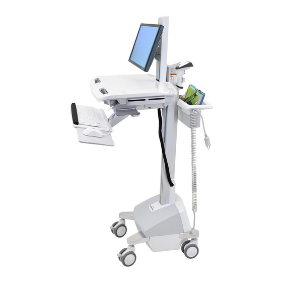
Ergotron StyleView SV42 Tech Sheet
Lift engine replacement for carts powered with sla
Hide thumbs
Also See for StyleView SV42:
- User manual (23 pages) ,
- Tech sheet (19 pages) ,
- Installation manual (10 pages)
Advertisement
Quick Links
Tech Sheet
StyleView SV42 SLA, LCD
Lift Engine Replacement for Carts powered with SLA
1x
1
Turn off all mounted equipment.
4
Remove monitor.
5
Remove front base cover.
888-05-051-G-00 rev. A • 02/15
2
Disconnect Power System
from power source.
WARNING
Impact Hazard!
Moving Parts can Crush and Cut.
Raise monitor to top of vertical
adjustment BEFORE removing.
Failure to heed this warning may result in
serious personal injury or property damage!
822-310
Estimated Completion Time
5/32" (4mm)
13mm
3
60
minutes
Turn power system off by
holding down the AC Outlet
Power button for 1 - 3 seconds.
Power light will shut off .
1/21
Advertisement

Related Manuals for Ergotron StyleView SV42


Summary of Contents for Ergotron StyleView SV42
- Page 1 Tech Sheet StyleView SV42 SLA, LCD Lift Engine Replacement for Carts powered with SLA Estimated Completion Time minutes 5/32" (4mm) 13mm Turn off all mounted equipment. Disconnect Power System Turn power system off by from power source. holding down the AC Outlet Power button for 1 - 3 seconds.
- Page 2 Tech Sheet StyleView SV42 SLA, LCD Remove rear base cover. Remove power module Loosen T-Slot retainer bracket and slide up. Do not remove screw, only loosen. Cut the table tie. 888-05-051-G-00 rev. A • 02/15 2/21...
- Page 3 Tech Sheet StyleView SV42 SLA, LCD Detach all cables from power module. Remove power module. Remove brackets, cam cover and cable routing channels 888-05-051-G-00 rev. A • 02/15 3/21...
- Page 4 Tech Sheet StyleView SV42 SLA, LCD Remove basket and handle. 180˚ 888-05-051-G-00 rev. A • 02/15 4/21...
- Page 5 Tech Sheet StyleView SV42 SLA, LCD Open worksurface. Unlock CPU and remove all contents in the storage area. Remove ground wire if present, then remove the four screws and Arm or Lift. If removed, save the star washer from the ground wire for reattachment.
- Page 6 Tech Sheet StyleView SV42 SLA, LCD Remove left rear worksurface portion and save for attachment to the new head unit. If present, disconnect the two UI cables and pull them down and out through the bottom of the head unit.
- Page 7 Tech Sheet StyleView SV42 SLA, LCD Unplug all cables from drawer controller. Pull cable up into storage area. Disconnect power cable. 888-05-051-G-00 rev. A • 02/15 7/21...
- Page 8 Tech Sheet StyleView SV42 SLA, LCD Remove bottom drawer cabinet. If you do not have a bottom drawer - continue to step 18. Remove the top drawer(s). Unscrew the bottom cabinet M4 x 12mm Slide bottom cabinet off . 888-05-051-G-00 rev. A • 02/15...
- Page 9 Tech Sheet StyleView SV42 SLA, LCD Remove drawer cabinet. If you do not have a drawer - continue to step 19. Disengage brake cable. Remove brake cover. 888-05-051-G-00 rev. A • 02/15 9/21...
- Page 10 Tech Sheet StyleView SV42 SLA, LCD Loosen nut. 13mm Remove ball end of cable from brake. Remove the bottom 2 screws from the head unit. 888-05-051-G-00 rev. A • 02/15 10/21...
- Page 11 Tech Sheet StyleView SV42 SLA, LCD 5/32" (4mm) Loosen screws Lift head unit off Remove screws. Unscrew and remove lift engine. 888-05-051-G-00 rev. A • 02/15 11/21...
- Page 12 Tech Sheet StyleView SV42 SLA, LCD Insert new lift engine and screw in. Hang head unit on screws. Insert two screws and leave them protruding to allow head unit to hang on them. Attach the two bottom screws and then tighten top two screws.
- Page 13 Tech Sheet StyleView SV42 SLA, LCD Engage brake cable. Insert ball end of cable into brake. 13mm Tighten cable tension tighten nut. (do not tigthten nut at this time). Replace brake cover. 888-05-051-G-00 rev. A • 02/15 13/21...
- Page 14 Tech Sheet StyleView SV42 SLA, LCD Attach drawer cabinet to lift engine. If you do not have a drawer - skip to step 30. Slide the bottom drawer cabinet only halfway onto the bottom tracks of the top drawer. If you do not have a bottom drawer - skip to step 29.
- Page 15 Tech Sheet StyleView SV42 SLA, LCD Screw in bottom cabinet. Slide bottom drawer on all the way. M4 x 12mm Slide all drawers into the cabinet. Pull cable down through storage area. Plug in drawer keypad cable, and USB cable.
- Page 16 Tech Sheet StyleView SV42 SLA, LCD Replace drawer controller cover. Reconnect power cable. If you disconnected the 2 UI cables, route them up into the new head unit and connect to the left rear worksurface portion you previously removed. 888-05-051-G-00 rev. A • 02/15...
- Page 17 Tech Sheet StyleView SV42 SLA, LCD Attach the left rear worksurface portion to the new head unit. Plug in all cables from the USB hub. Reattach arm or lift with the 4 screws and ground wire with star washer. 5/32" (4mm) 888-05-051-G-00 rev.
- Page 18 Tech Sheet StyleView SV42 SLA, LCD Replace basket and handle. Attach cable routing cables, cam cover and brackets 888-05-051-G-00 rev. A • 02/15 18/21...
- Page 19 Tech Sheet StyleView SV42 SLA, LCD Install power module Place power module in base. Attach all cables from power module. Loosen T-Slot retainer bracket and slide down. Do not remove screw, only loosen. 888-05-051-G-00 rev. A • 02/15 19/21...
- Page 20 Tech Sheet StyleView SV42 SLA, LCD Replace rear base cover. Replace front base cover. WARNING Reattach monitor. Impact Hazard! Moving Parts can Crush and Cut. Raise monitor to top of vertical adjustment BEFORE removing. Failure to heed this warning may result in...
- Page 21 Tech Sheet StyleView SV42 SLA, LCD Replace all contents in the storage area. Attach CPU lock cable. © 2015 Ergotron, Inc. 888-05-051-G-00 rev. A • 02/15 21/21...
Need help?
Do you have a question about the StyleView SV42 and is the answer not in the manual?
Questions and answers