Advertisement
Quick Links
Features & Specifi cations .................................................... 3
Set-up .............................................................................. 4 - 8
Adjustment ................................................................... 9 - 10
Ergonomics ........................................................................ 11
Maintenance & Safety ................................................ 11 - 12
Dimensions ........................................................................ 13
For the latest User Installation Guide and StyleLink Software Download please visit: www.ergotron.com
English, Español, Français, Deutsch, Nederlands, Italiano, Svenska, 日本語, 汉语
www.ergotron.com |
USA: 1-800-888-8458
888-24-257-G-00 rev. D • 06/19
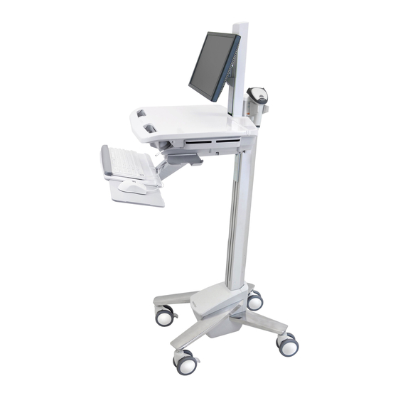
Electronic Medical Records (EMR Cart)
|
Europe: +31 (0)33-45 45 600
StyleView
|
|
China: 400-120-3051
Japan: japansupport@ergotron.com
SV40
®
with LCD Mount
English
1 of 13
Advertisement

Related Manuals for Ergotron StyleView SV40


Summary of Contents for Ergotron StyleView SV40
-
Page 1: Table Of Contents
Ergonomics ................ 11 Maintenance & Safety ..........11 - 12 Dimensions ................ 13 English For the latest User Installation Guide and StyleLink Software Download please visit: www.ergotron.com English, Español, Français, Deutsch, Nederlands, Italiano, Svenska, 日本語, 汉语 www.ergotron.com | USA: 1-800-888-8458... - Page 2 Set-up M5 x 12mm M4 x 5mm M4 x 10mm M4 x 10mm M4 x 8mm M4 x 8mm Tools Needed 10mm 14mm (9/16") 2 of 13 888-24-257-G-00 rev. D • 06/19...
-
Page 3: Features & Specifi Cations
Minimisez la tension d’ é lévation AVANT : de retirer l’ é quipement fixé, d’ e xpédier le chariot, de stocker le chariot www.ergotron.com 826-501 Height Adjustable LCD Mount attaches LCDs or tablet PC's with 75x75 or 100x100mm mounting interface Worksurface 2a. -
Page 4: Set-Up
Set-up Release Brake to move riser. 4 of 13 888-24-257-G-00 rev. D • 06/19... - Page 5 Set-up 0˚ 0˚ M4 x 5mm 75x75mm / 100x100mm WARNING M4 x 10mm Impact Hazard! Moving Parts can Crush and Cut. Raise monitor to top of vertical adjustment BEFORE removing. Failure to heed this warning may result in serious personal injury or property damage! 822-310 5 of 13 888-24-257-G-00 rev.
- Page 6 Set-up Place computer in compartment. Do not place power bricks in compartment. M4 x 10mm WARNING! Power brick should be stored under the storage area. Failure to follow these instructions may cause over heating and result in product damage. M5 x 12mm 6 of 13 888-24-257-G-00 rev.
- Page 7 Set-up Route power cable down along tower. WARNING! DO NOT OPERATE WITHOUT GUARD IN PLACE. Only WARNING remove guard when routing a cable with a large connector through the bottom of the compartment. Replace guard imediately after DO NOT OPERATE routing cable.
- Page 8 Set-up OVERHEATING CAUTION: Failure to follow these cautions may cause overheating and result in equipment damage. • DO NOT OBSTRUCT AIR VENTS! • Computer Fan must face the carts ventilation openings on either side of the compartment. • If your computer does NOT have a fan, remove the 2 side covers and leave them off to increase airfl ow. If your computer has a fan, removing the 2 side covers for increased airfl ow is optional.
-
Page 9: Adjustment
Adjustment It is important that you adjust this product according to the weight of the mounted equipment as described in the following steps. Any time equipment is added or removed from this product, resulting in a change in the weight of the mounted load, you should repeat these adjustment steps to ensure safe and optimum operation. Adjustments should move smoothly and easily through the full range of motion and stay where you set it. - Page 10 Élevez l’ é cran au plus haut de l’ajustement vertical AVANT de le retirer. NE retirez PAS la vis d’arrêt avant que l’ é cran soit fixé. Dans un tel cas, le pivot d'écran se relèverait rapidement et cela pourrait engendrer des blessures. www.ergotron.com 822-055 10 of 13 888-24-257-G-00 rev. D • 06/19...
-
Page 11: Ergonomics
Ergonomics Moving Working stow - before you go customize - to your size 1 During normal movement, release brake and lower worksurface to lowest 1 Set top of monitor screen about one inch below eye level - Release brake and lift or lower riser position for optimal stability and unobstructed view. - Page 12 CAUTION: Release Lift Brake before moving work surface! Moving work surface while Lift Brake is engaged may cause serious damage to Lift Engine. WARNING: In the event that repair of the StyleView Cart is needed, contact Ergotron Customer Care immediately. Cart repair can only be performed by Ergotron, Inc. or by an Ergotron authorized agent.
-
Page 13: Dimensions
(330 mm) Side View Top View For Warranty visit: www.ergotron.com/warranty For Service visit: www.ergotron.com For local customer care phone numbers visit: http://contact.ergotron.com www.ergotron.com | USA: 1-800-888-8458 Europe: +31 (0)33-45 45 600 China: 400-120-3051 Japan: japansupport@ergotron.com © 2013 Ergotron, Inc. All rights reserved.
Need help?
Do you have a question about the StyleView SV40 and is the answer not in the manual?
Questions and answers