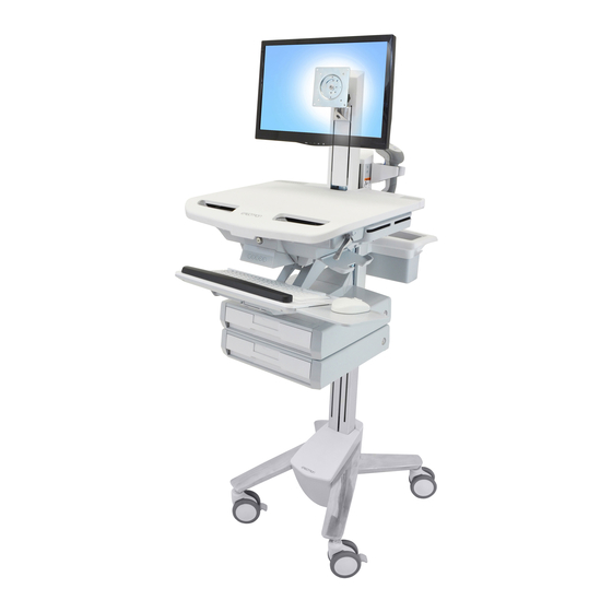
Ergotron StyleView User Manual
Telepresence kit for single lcd cart
Hide thumbs
Also See for StyleView:
- User's installation manual (40 pages) ,
- Manual (28 pages) ,
- User manual (23 pages)
Table of Contents
Advertisement
Quick Links
NOTE: This kit is intended to be attached to a cart with single LCD pivot and one drawer.
Safety ........................................................................................................................ 2
Features & Specifi cations ...................................................................................................... 3
Tools Needed & Components ................................................................................................4
Drawer ................................................................................................................................ 5 - 9
CPU Holder .....................................................................................................................10 - 12
Camera Shelf ..................................................................................................................13 - 14
Adjustment .......................................................................................................................... 15
To Stop Independent LCD Lift ..............................................................................................16
Maintenance & Safety ...................................................................................................17 - 18
For local customer care phone numbers visit: http://contact.ergotron.com
888-97-333-G-00 rev. A • 09/13
StyleView® Telepresence Kit
for Single LCD Cart
www.ergotron.com
User's Guide - English
Guía del usuario - Español
Manuel de l'utilisateur - Français
Benutzerhandbuch - Deutsch
Gebruikersgids - Nederlands
Guida per l'utente - Italiano
Användarhandbok - svenska
ユーザーガイ ド : 日本語
用户指南 : 汉语
User Guide
Reduce
Reuse
Recycle
1 of 18
Advertisement
Table of Contents

Summary of Contents for Ergotron StyleView
-
Page 1: Table Of Contents
User's Guide - English Guía del usuario - Español Manuel de l’utilisateur - Français Benutzerhandbuch - Deutsch For local customer care phone numbers visit: http://contact.ergotron.com Gebruikersgids - Nederlands Guida per l’utente - Italiano Användarhandbok - svenska ユーザーガイ ド : 日本語... -
Page 2: Safety
For More information and instructions refer to product unstable. guide at http://4support.ergotron.com or contact Ergotron Customer Care at 1-800-888-8458. 822-052 888-97-333-G-00 rev. A • 09/13 2 of 18... -
Page 3: Features & Specifi Cations
Features & Specifi cations 11.8" Weight Capacity (300 mm) With Independent LCD Lift: Without Independent LCD Lift: 6-14 lbs (2.7-6.4 kg) 20 lbs (9 kg)* * See "How To Eliminate Independent LCD Lift" section 0 lbs (0 kg) Open Worksurface <5 lbs (2.3 kg) Closed Worksurface <2 lbs (0.9 kg) -
Page 4: Tools Needed & Components
Tools Needed 10mm 14mm (9/16") Components M4 x 6mm M4 x 14mm M4 x 25mm M3 x 22mm M4 x 12mm M5 x 10mm 10-24 x 1/2” 888-97-333-G-00 rev. A • 09/13 4 of 18... -
Page 5: Drawer
Attach the Travel Stop bracket to the lift engine to keep the drawer from hitting the base. M3 x 22mm Slide the drawer only half way onto the bottom tracks of the existing top drawer. 888-97-333-G-00 rev. A • 09/13 5 of 18... - Page 6 Remove the top cover on the top drawer and route the cable attached to the bottom drawer up into the control panel on the top drawer. Powered Carts Non-Powered Carts Slide the drawer completely onto the bottom tracks of the top drawer.
- Page 7 Replace the top cover on the top drawer. Remove the top drawer(s). Secure the bottom drawer by attaching M4 x 12mm the two screws. Replace the top drawer(s). 888-97-333-G-00 rev. A • 09/13 7 of 18...
- Page 8 On Powered Carts only, reset drawer power so keypad will recognize added drawer. NOTE: This step is not needed on Non-Powered Carts. Turn power system off by Disconnect Power System from power source. Turn off all mounted equipment. holding down the AC Outlet Power button for 1 - 3 seconds.
-
Page 9: G-00 Rev. A
Insert divider. 888-97-333-G-00 rev. A • 09/13 9 of 18... -
Page 10: Cpu Holder
180˚ M5 x 10mm 888-97-333-G-00 rev. A • 09/13 10 of 18... - Page 11 888-97-333-G-00 rev. A • 09/13 11 of 18...
- Page 12 888-97-333-G-00 rev. A • 09/13 12 of 18...
-
Page 13: Camera Shelf
NOTE: camera is supplied Max weight: 2 lbs (1 kg) by customer. If your monitor has recessed mounting holes, M4 x 6mm you need to add the provided spacer between the monitor and the mounting plate. M4 x 14mm M4 x 14mm 888-97-333-G-00 rev. - Page 14 3 Mounting Options 888-97-333-G-00 rev. A • 09/13 14 of 18...
-
Page 15: Adjustment
Adjustment Step It is important that you adjust this product according to the weight of the mounted equipment as described in the following steps. Any time equipment is added or removed from this product, resulting in a change in the weight of the mounted load, you should repeat these adjustment steps to ensure safe and optimum operation. Adjustments should move smoothly and easily through the full range of motion and stay where you set it. -
Page 16: To Stop Independent Lcd Lift
3. Remove monitor. Failure to heed this warning may result in serious personal injury or property damage! For More information and instructions refer to product guide at http://4support.ergotron.com or contact Ergotron Customer Care at 1-800-888-8458. 822-055 888-97-333-G-00 rev. A • 09/13... -
Page 17: Maintenance & Safety
Guidance and Manufacturer’s Declaration – Electromagnetic Immunity Ergotron's Medical Grade Power Strip is intended for use in the Ergotron's Medical Grade Power Strip is intended for use in the electromagnetic environment electromagnetic environment specifi ed below. The customer or the user specifi ed below. - Page 18 It is recommended that any cleaning solution be tested on a small, inconspicuous area to ensure surface is not harmed. Adjustment, Service, Replacement - DO NOT attempt to adjust, service or replace any part of the Power Strip unless directed to do so through Ergotron-approved documentation (i.e.


Need help?
Do you have a question about the StyleView and is the answer not in the manual?
Questions and answers