Ergotron StyleView SV41 User Manual
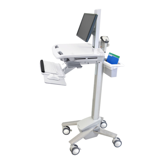
Cart with lcd mount
Hide thumbs
Also See for StyleView SV41:
- User manual (9 pages) ,
- Tech sheet (3 pages) ,
- User manual (13 pages)
Advertisement
Quick Links
For the latest User Installation Guide and StyleLink Software Download please visit:
Encontrará la versión más reciente del manual de instalación del usuario y el software de StyleLink en:
Si vous souhaitez télécharger le dernier manuel d'installation de l'utilisateur ou le logiciel StyleLink, rendez-vous sur :
Den neuesten Installationsleitfaden für Benutzer sowie den neuesten StyleLink-Softwaredownload fi nden Sie unter:
Voor de nieuwste Installatiehandleiding voor de gebruiker en voor het downloaden van StyleLink-software gaat u naar:
Per scaricare le versioni più recenti del manuale di installazione e del software StyleLink, andare al sito:
De senaste versionerna av installationshandledningen och nedladdning av programvaran för StyleLink fi nns på:
最新版ユーザインス トールガイ ドとスタイルリンク ソフ トウェアは次のサイ トでダウンロードできます。
请从下列地址获取最新版本的用户安装指南和 StyleLink 软件下载:
사용자 설치 안내서 및 StyleLink 소프트웨어 다운로드는 다음 웹 사이트에서 제공하고 있습니다.
http://4support.ergotron.com
User's Guide - English
Guía del usuario - Español
Manuel de l'utilisateur - Français
Gebruikersgids - Nederlands
Benutzerhandbuch - Deutsch
Guida per l'utente - Italiano
Användarhandbok - svenska
ユーザーガイ ド : 日本語
用户指南 : 汉语
사용자 안내서 : 대한민국
IMPORTANT! This product will need tension adjustments once installation is complete.
Make sure all equipment is properly installed on the product before attempting range
of motion or tension adjustments. Any time equipment is added or changed on this
product resulting in a diff erent mounted weight, you should repeat the adjustment
steps to ensure safe and optimum operation. This product should move smoothly and
easily through the full range of motion and stay where you set it. If movement is diffi cult
or the product does not stay where you set it, follow the adjustment instructions to
loosen or tighten the tension to create a smooth, easy motion. Depending on your
product and the adjustment, it may take many turns to notice a diff erence.
Features & Specifi cations ............................................... 2 - 4
Set-up ............................................................................ 5 - 14
Adjustment ................................................................. 11- 12
Auto-Lock Drawer ...............................................................13
Ergonomics .........................................................................14
Maintenance & Safety ................................................ 14 - 16
888-24-211-G-00 rev. C • 11/12
1x
1
1x
2
1x
3
4x
4
8x
1x
5
4x
6
1x
7
1x
8
1x
9
EN
User Guide
StyleView® SV41
Cart with LCD Mount
A
4x
12x
1x
2x
M4 x 5mm
1x
2x
M4 x 10mm
M4 x 10mm
2x
1x
M3.5 x 6mm
1x
1x
1x
1x
4mm
1x
1x
1x
M4 x 8mm
14mm (9/16")
10mm
B
3x
M4 x 8mm
3mm
2x
M4 x 12mm
1/16
Advertisement

Subscribe to Our Youtube Channel
Related Manuals for Ergotron StyleView SV41


Summary of Contents for Ergotron StyleView SV41
- Page 1 De senaste versionerna av installationshandledningen och nedladdning av programvaran för StyleLink fi nns på: 最新版ユーザインス トールガイ ドとスタイルリンク ソフ トウェアは次のサイ トでダウンロードできます。 请从下列地址获取最新版本的用户安装指南和 StyleLink 软件下载: 사용자 설치 안내서 및 StyleLink 소프트웨어 다운로드는 다음 웹 사이트에서 제공하고 있습니다. http://4support.ergotron.com User's Guide - English Guía del usuario - Español Manuel de l’utilisateur - Français...
-
Page 2: Features And Specifications
Changes or modifi cations not expressly approved by Ergotron, Inc. could void the user’s authority to operate the equipment. Please contact Ergotron for complete EMC compatibility information. - Page 3 Features & Specifi cations Part Number Auto-Lock Drawer SV41-3310-0 1 Drawer*/16 compartments SV41-3320-0 2 Drawers*/32 compartments SV41-3340-0 4 Drawers*/28 compartments SV41-3360-0 6 Drawers*/24 compartments *Auto-Lock Drawer 1 Drawer 2 Drawers 4 Drawers 6 Drawers 2.5" 10.5" 10.5" (64 mm) (267 mm) (267 mm) 3.75"...
- Page 4 Features & Specifi cations 14.63" 19.5" (372 mm) (495 mm) 7" - 12" 17" (178-305 mm) (432 mm) 13.4" 50.5" 3.27" 3.4" (340 mm) (1282 mm) (83 mm) (86 mm) 7.4" (188 mm) 31" - 51" 15.4" (787-1295 mm) 40" 2.9"...
- Page 5 Set-up CAUTION: Close worksurface before opening drawers. Open only one drawer at a time. Do Not push cart when drawers or worksurface are open. Failure to follow these instructions may cause the cart to be unstable. Release Brake to move riser.
- Page 6 Set-up 888-24-211-G-00 rev. C • 11/12 6/16...
- Page 7 Set-up Connect Keyboard and Mouse to USB Hub USB (Type A) USB (Type A) NOTE: Bar Code Scanner should be connected directly to computer USB port. DO NOT connect Bar Code Scanner to the USB Hub. 0˚ 0˚ M4 x 5mm 75x75mm / 100x100mm WARNING M4 x 10mm...
- Page 8 Set-up To increase space and improve airfl ow, power brick may be stored under the storage area. M4 x 12mm Route power cable down along tower. WARNING! DO NOT OPERATE WITHOUT GUARD IN PLACE. Only WARNING remove guard when routing a cable with a large connector through the bottom of the compartment.
- Page 9 Set-up Place computer and AC power adaptors in compartment. Do not place power bricks near computer or compartment air vents. M4 x 10mm Plug the following factory connected cables into your computer. USB: This cable runs from the USB Hub to your computer and uses your computer to power the USB Hub, Keyboard Lights and Fan. (NOTE: Your computer must be turned on for the USB Hub, Keyboard Lights and Fan to function).
- Page 10 Set-up Placement of CPU's in Secure Storage Area: USFF (Ultra Small Form Factor) Thin Client DO NOT OBSTRUCT AIR VENTS! Obstructing air vents may cause overheating and result in equipment damage. Center CPU in storage area. To increase space and improve airfl ow, power brick may be stored under the storage area.
- Page 11 Set-up Adjustment It is important that you adjust this product according to the weight of the mounted equipment as described in the following steps. Any time equipment is added or removed from this product, resulting in a change in the weight of the mounted load, you should repeat these adjustment steps to ensure safe and optimum operation.
- Page 12 3. Remove monitor. Failure to heed this warning may result in serious personal injury or property damage! For More information and instructions refer to product guide at http://4support.ergotron.com or contact Ergotron Customer Care at 1-800-888-8458. 822-055 888-24-211-G-00 rev. C • 11/12...
- Page 13 -Make sure drawer is fully closed before entering PIN. • Drawer won’t open when User PIN is entered -Test system by entering Master PIN. If drawer doesn’t unlock, contact Ergotron customer care for "Lost Master PIN" instructions. 888-24-211-G-00 rev. C • 11/12 13/16...
- Page 14 Set-up Keyboard Light 1. Turn Computer on. 2. Test Keyboard Light. Keyboard Light will automatically turn off after 15 minutes if not manually turned off . Ergonomics Moving Working stow - before you go customize - to your size 1 During normal movement, release brake and lower worksurface to 1 Set top of monitor screen about one inch below eye level - Release brake and lift or lower riser lowest position for optimal stability and unobstructed view.
-
Page 15: Maintenance And Safety
CAUTION: Release Lift Brake before moving work surface! Moving work surface while Lift Brake is engaged may cause serious damage to Lift Engine. WARNING: In the event that repair of the StyleView Cart is needed, contact Ergotron Customer Care immediately. Cart repair can only be performed by Ergotron, Inc. or by an Ergotron authorized agent. - Page 16 Maintenance & Safety Recommended Periodic Inspection and Maintenance Component Action How often By whom UI, Ethernet, USB Inspect for wear, pinching, bad Monthly Any user cables connectors Inspect for dust at intake, vacuum Fan on side of CPU as required using a vacuum cleaner Monthly Any user compartment...
Need help?
Do you have a question about the StyleView SV41 and is the answer not in the manual?
Questions and answers