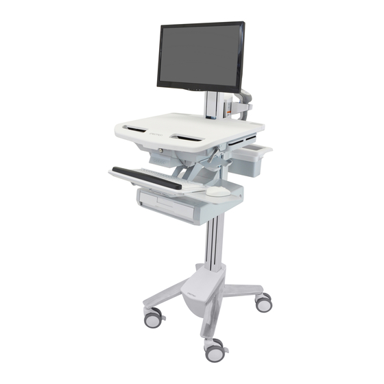
Ergotron StyleView SV43 Tech Sheet
Lift engine replacement for carts
Hide thumbs
Also See for StyleView SV43:
- User manual (20 pages) ,
- User manual (17 pages) ,
- User manual (8 pages)
Advertisement
Quick Links
Tech Sheet
StyleView SV43
Lift Engine Replacement for Carts
1x
1
Turn off all mounted equipment.
3
Remove monitor.
888-05-079-G-00 rev. A • 09/22
2
Disconnect all mounted equipment
from power source.
WARNING
Impact Hazard!
Moving Parts can Crush and Cut.
Raise monitor to top of vertical
adjustment BEFORE removing.
Failure to heed this warning may result in
serious personal injury or property damage!
822-310
Tools Needed
13mm
13mm
4mm
Estimated Completion Time
40
minutes
14mm (9/16")
1/17
Advertisement

Related Manuals for Ergotron StyleView SV43


Summary of Contents for Ergotron StyleView SV43
- Page 1 Tech Sheet StyleView SV43 Lift Engine Replacement for Carts Estimated Completion Time minutes Tools Needed 13mm 13mm 14mm (9/16") Turn off all mounted equipment. Disconnect all mounted equipment from power source. WARNING Remove monitor. Impact Hazard! Moving Parts can Crush and Cut.
- Page 2 Tech Sheet StyleView SV43 Remove rear base cover. Remove front base cover. REAR VIEW Remove basket and handle. 180˚ 888-05-079-G-00 rev. A • 09/22 2/17...
- Page 3 Tech Sheet StyleView SV43 Open worksurface. Unlock CPU and remove all contents in the storage area. Remove the four screws and Arm or Lift. Unplug all cables from the USB hub. 888-05-079-G-00 rev. A • 09/22 3/17...
- Page 4 Tech Sheet StyleView SV43 Remove drawer keypad if present. Remove drawer controller cover. Unplug all cables from drawer controller. Pull cable up into storage area. 888-05-079-G-00 rev. A • 09/22 4/17...
- Page 5 Tech Sheet StyleView SV43 Remove bottom drawer cabinet. If you do not have a bottom drawer - continue to step 13. Remove the top drawer(s). Unscrew the bottom cabinet M4 x 12mm Slide bottom cabinet off . 888-05-079-G-00 rev. A • 09/22...
- Page 6 Tech Sheet StyleView SV43 Remove bottom drawer cabinet from lift engine. If you do not have a bottom drawer - continue to step 14 Disengage brake cable. Remove brake cover. 888-05-079-G-00 rev. A • 09/22 6/17...
- Page 7 Tech Sheet StyleView SV43 Loosen nut. 13mm Remove ball end of cable from brake. Remove the bottom 2 screws from the head unit. 888-05-079-G-00 rev. A • 09/22 7/17...
- Page 8 Tech Sheet StyleView SV43 Loosen screws Lift head unit off Remove screws. Unscrew and remove lift engine. 13mm 888-05-079-G-00 rev. A • 09/22 8/17...
- Page 9 Tech Sheet StyleView SV43 Insert new lift engine and screw in. 13mm Hang head unit on screws. Insert two screws and leave them protruding to allow head unit to hang on them. Attach the two bottom screws, then tighten top two screws.
- Page 10 Tech Sheet StyleView SV43 Engage brake cable. 13mm Insert ball end of cable into brake. Tighten cable tension tighten nut. (do not tigthten nut at this time). Replace brake cover. 888-05-079-G-00 rev. A • 09/22 10/17...
- Page 11 Tech Sheet StyleView SV43 Attach drawer cabinet to lift engine. If you do not have a drawer - skip to step 27. 888-05-079-G-00 rev. A • 09/22 11/17...
- Page 12 Tech Sheet StyleView SV43 Slide the bottom drawer cabinet only halfway onto the bottom tracks of the top drawer. If you do not have a bottom drawer skip to step 24. Plug the bottom drawer cable into the top drawer interface.
- Page 13 Tech Sheet StyleView SV43 Slide all drawers into the cabinet. Pull cable down through storage area. Plug in drawer keypad cable, and USB cable. Replace drawer controller cover. 888-05-079-G-00 rev. A • 09/22 13/17...
- Page 14 Tech Sheet StyleView SV43 Plug in all cables from the USB hub. Reattach arm or lift with the 4 screws. 888-05-079-G-00 rev. A • 09/22 14/17...
- Page 15 Tech Sheet StyleView SV43 Replace basket and handle. Replace front base cover. Replace rear base cover. REAR VIEW 888-05-079-G-00 rev. A • 09/22 15/17...
- Page 16 Tech Sheet StyleView SV43 WARNING Reattach monitor. Impact Hazard! Moving Parts can Crush and Cut. Raise monitor to top of vertical adjustment BEFORE removing. Failure to heed this warning may result in serious personal injury or property damage! 822-310 Replace all contents in the storage area.
- Page 17 Tech Sheet StyleView SV43 It is important that you adjust this product according to the weight of the mounted equipment as Adjust new lift engine. described in the following steps. Any time equipment is added or removed from this product, resulting in a change in the weight of the mounted load, you should repeat these adjustment steps to ensure safe and optimum operation.
Need help?
Do you have a question about the StyleView SV43 and is the answer not in the manual?
Questions and answers