Pego ECP200 BASE 4A Use Manual
Electronics board
Hide thumbs
Also See for ECP200 BASE 4A:
- Use and maintenance manual (32 pages) ,
- User and maintenance manual (28 pages) ,
- Quick manual (16 pages)

Related Manuals for Pego ECP200 BASE 4A


Summary of Contents for Pego ECP200 BASE 4A
- Page 1 ELECTRONICS BOARD ECP200 BASE 4 / 4A Use manual READ AND KEEP ELECTRICAL BOARDS FOR REFRIGERATING INSTALLATIONS REV. 02-18...
- Page 2 E. BOARD ECP200 BASE 4/4A The ECP200 BASE 4/4A electronic board is installed in the following families of Pego standard electrical panels: 110300BVD*** 110400BVD*** 110750BVD*** 1101000BVDB* 110300BVDE** 110300BVDEM* 110400BVDE** 110750BVDE** 1101000BVDE* ...
-
Page 3: Chapter 1: Technical Characteristics
CHAP. 1 - Technical characteristics E. BOARD ECP200 BASE 4/4A CHAPTER 1: TECHNICAL CHARACTERISTICS TECHNICAL CHARACTERISTICS OF THE ELECTRONICS BOARD Power supply of the electronics board 230 V~ 10% 50-60Hz Voltage Max power (only electronics) ~ 7 VA Rated current (With all loads connected) Climatic conditions of the electronics board Working temperature... -
Page 4: Chapter 2: Parameter Programming
CHAP. 2 - Parameter programming E. BOARD ECP200 BASE 4/4A CHAPTER 2: PARAMETER PROGRAMMING CONTROL PANEL FRONT KEYPAD AUXILIARY RELAY CONTROL (on the version with alarm relay, it manually ... -
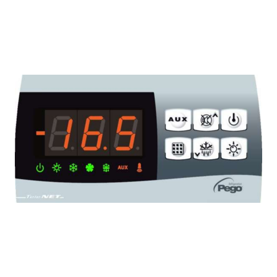
Page 5: Led Display
CHAP. 2 - Parameter programming E. BOARD ECP200 BASE 4/4A LED DISPLAY Cold room temperature / parameters Stand-by (flashes on stand-by. Outputs are deactivated) Room light (flashes if door switch activated) Cold (indicates activation of compressor) Fans Defrosting Ausiliary... -
Page 6: Key To Symbols
CHAP. 2 - Parameter programming E. BOARD ECP200 BASE 4/4A GENERAL To enhance safety and simplify the operator’s work, the ECP200 BASE has two programming levels; the first level (Level 1) is used to configure the frequently-modified SETPOINT parameters. The second programming level (Level 2) is for general parameter programming of the various controller work modes. - Page 7 CHAP. 2 - Parameter programming E. BOARD ECP200 BASE 4/4A LEVEL 1 PROGRAMMING (User level) To gain access to the Level 1 configuration menu proceed as follows: 1. Press the () and () keys simultaneously and keep them pressed for a few seconds until the first programming variable appears on the display.
- Page 8 CHAP. 2 - Parameter programming E. BOARD ECP200 BASE 4/4A LEVEL 2 PROGRAMMING (Installer level) To access the second programming level press the UP () and DOWN () keys and the LIGHT key simultaneously for a few seconds. When the first programming variable appears the system automatically goes to stand-by. 1.
- Page 9 CHAP. 2 - Parameter programming E. BOARD ECP200 BASE 4/4A 0 = NO Compressor protection contact status 0 = NO 1 = NC Compressor safety time door switch. When the door is opened the 0…5 min evaporator fans shut down and the compressor will continue working for time doC, after which it will shut down.
-
Page 10: Manual Defrosting
CHAP. 2 - Parameter programming E. BOARD ECP200 BASE 4/4A 0 = only display set point 1 = display set point, AUX, light access Password type of protection 2 = access in programming ( active when PA is not equal 0) not permitted 3 = access in second level programming not... -
Page 11: Hot Gas Defrosting
CHAP. 2 - Parameter programming E. BOARD ECP200 BASE 4/4A HOT GAS DEFROSTING 2.13 Set parameter d1=1 to defrost in cycle inversion mode. The compressor relay and defrost relay are activated throughout the defrost phase. To ensure proper control of the system the installer must use the defrost output: this must allow opening of the cycle inversion solenoid valve and closure of the liquid solenoid valve. -
Page 12: Chapter 3: Options
NET CONFIGURATION WITH MODBUS-RTU PROTOCOL For RS485 connections with Modbus-RTU protocol, to enable RS485 output as indicated at chapter 3.3 and follow the scheme below. Refer to MODBUS-RTU_ECP200T1 user manual (available on Pego Internet web site) for MODBUS-RTU communication protocol specification. USE MANUAL Page 12 Rev. - Page 13 CAP. 3 - Opzioni E. BOARD ECP200 BASE 4/4A ALARM RELAY / RS485 SWITCHING Remove power from the electrical panel, open the front panel and unscrew the 6 fixing screws of the electronic board. Configure the jumper from JUMPER JP2 (placed on the front of electrical board near the display far down on the right) following one of the ensuing options.
-
Page 14: Chapter 4: Troubleshooting
CHAP. 4 - Troubleshooting E. BOARD ECP200 BASE 4/4A CHAPTER 4: TROUBLESHOOTING TROUBLESHOOTING In the event of any anomalies the ECP200 BASE warns the operator by displaying alarm codes and sounding the warning buzzer inside the control panel. If an alarm is tripped the display will show one of the following messages. - Page 15 Appendices E. BOARD ECP200 BASE 4/4A APPENDICES ECP200 BASE4 WIRING DIAGRAM Voltage free contact ECP200 BASE4A WIRING DIAGRAM Voltage free contact USE MANUAL Page 15 Rev. 02-18...
- Page 16 Tel. +39 0425 762906 Fax +39 0425 762905 e.mail: info@pego.it – www.pego.it AFTER-SALES ASSISTANCE SERVICE Tel. +39 0425 762906 e.mail: tecnico@pego.it Distributor: USE MANUAL Page 16 Rev. 02-18 PEGO s.r.l. reserves the right to make amendments to this user manual at any moment.
Need help?
Do you have a question about the ECP200 BASE 4A and is the answer not in the manual?
Questions and answers