Pego ECP200 BASE 2 Use And Maintenance Manual
Hide thumbs
Also See for ECP200 BASE 2:
- Use and maintenance manual (32 pages) ,
- User and maintenance manual (28 pages) ,
- Use manual (17 pages)

Related Manuals for Pego ECP200 BASE 2


Summary of Contents for Pego ECP200 BASE 2
- Page 1 ECP200 BASE 2 / 4 Use and maintenance manual READ AND KEEP REV. 02‐09 ELECTRICAL BOARDS FOR REFRIGERATING INSTALLATIONS...
-
Page 2: Table Of Contents
EC declaration of conformity Pag. 21 ECP200 BASE 4 wiring diagram Pag. 21 ECP200 BASE 4A wiring diagram Pag. 22 ECP200 BASE 2 wiring diagram Pag. 22 ECP200 BASE 2A wiring diagram Pag. 23 Connection example (1) - ECP200 BASE4 /BASE4A Pag. 23 Connection example (2) - ECP200 BASE4 /BASE4A Pag. - Page 3 CHAP. 1 - Introduction ECP200 BASE 2/4 CHAPTER 1: INTRODUCTION GENERAL DESCRIPTION: The ECP200 BASE is a new control panel for cold rooms with a single-phase compressor up to 2 HP, specially designed to provide the user with safety, protection, control and ease of installation.
-
Page 4: Ecp200 Base
ECP200 BASE 2/4 PRODUCT ID CODES ECP200 BASE 2 controls and manages compressor and room light. ECP200 BASE 2 A controls and manages compressor and room light. Alarms relay. ECP200 BASE 4 controls and manages compressor, defrosting elements, evaporator fans and room light. -
Page 5: General
CHAP. 2 - Installation ECP200 BASE 2/4 IDENTIFICATION DATA The unit described in this manual has an ID plate on the side showing all the relevant identification data: • Name of Manufacturer • Code and model of unit electrical board •... - Page 6 CHAP. 2 - Installation ECP200 BASE 2/4 INSTALLING THE UNIT Fig. 1 : Undo the 4 screws on the front of the panel. Fig. 2 : Use the three existing holes to fix the box back panel to the wall: use three screws of a length suitable for the thickness of the wall to which the panel will be attached.
-
Page 7: Technical Characteristics
CHAP. 3 - Technical characteristics ECP200 BASE 2/4 CHAPTER 3: TECHNICAL CHARACTERISTICS TECHNICAL CHARACTERISTICS Power supply 230 V~ ± 10% 50Hz / 60Hz Voltage Max power (only electronics) ~ 7 VA Rated current (With all loads connected) Climatic conditions Working temperature -5 ÷... -
Page 8: Warranty
• Damages caused by natural phenomena as lightning, natural calamities, etc. Warranty cover may be refused if the device is modified or changed. Under no circumstances Pego S.r.l. will be responsible for possible loss of data and information, costs of substitutive goods or services, damages to things, people or animals,... -
Page 9: Control Panel
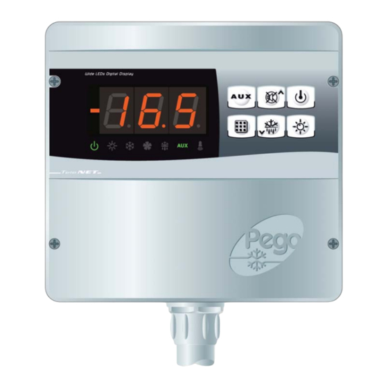
CHAP. 5 - Parameter programming ECP200 BASE 2/4 CHAPTER 5: PARAMETER PROGRAMMING CONTROL PANEL FRONT KEYPAD AUXILIARY RELAY CONTROL (on the version with alarm relay controls the relay manual if parameter AU=1) UP / MUTE BUZZER ALARM STAND BY (if the system shuts down the LED flashes) - Page 10 CHAP. 5 - Parameter programming ECP200 BASE 2/4 DOWN / MANUAL DEFROST ROOM LIGHT LED DISPLAY Cold room temperature / parameters Stand-by (flashes on stand-by. Outputs are deactivated) Room light (flashes if door switch activated) Cold (indicates activation of compressor)
- Page 11 CHAP. 5 - Parameter programming ECP200 BASE 2/4 GENERAL To enhance safety and simplify the operator’s work, the ECP200 EXPERT has two programming levels; the first level (Level 1) is used to configure the frequently-modified SETPOINT parameters. The second programming level (Level 2) is for general parameter programming of the various controller work modes.
- Page 12 ECP200 BASE 2/4 LEVEL 1 PROGRAMMING (User level) To gain access to the Level 1 configuration menu proceed as follows: 1. Press the (t) and (u) keys simultaneously and keep them pressed for a few seconds until the first programming variable appears on the display.
- Page 13 CHAP. 5 - Parameter programming ECP200 BASE 2/4 LEVEL 2 PROGRAMMING (Installer level) To access the second programming level press the UP (t) and DOWN (u) keys and the LIGHT key simultaneously for a few seconds. When the first programming variable appears the system automatically goes to stand-by.
- Page 14 ECP200 BASE 2/4 CHAP. 5 - Parameter programming Minimum and maximum temperature 1…240 min 120 min signalling and alarm display delay Minimum time between shutdown and subsequent switching on of the 0…15 min 0 min compressor. -10…+10 Cold room sensor value correction...
- Page 15 CHAP. 5 - Parameter programming ECP200 BASE 2/4 0 = only display set point 1= display set point, AUX, light access Password type of protection 2= access in programming ( active when PA is not equal 0) not permitted 3= access in second level...
- Page 16 ECP200 BASE 2/4 HOT GAS DEFROSTING 5.14 Set parameter d1 =1 to defrost in cycle inversion mode. The compressor relay and defrost relay are activated throughout the defrost phase. To ensure proper control of the system the installer must use the defrost output: this must allow opening of the cycle inversion solenoid valve and closure of the liquid solenoid valve.
-
Page 17: Telenet Monitoring / Supervision System
For RS485 connections with Modbus-RTU protocol, to enable RS485 output as indicated at chapter 6.3 and follow the scheme below. Refer to MODBUS-RTU_ECP200T1 user manual (available on Pego Internet web site) for MODBUS-RTU communication protocol specification. USE AND MAINTENANCE MANUAL Page 17 Rev. - Page 18 CAP. 6 - Opzioni ECP200 BASE 2/4 ALARM RELAY / RS485 SWITCHING Open the front of the box as described in Chap. 2.3 (page 6): rotate it downwards 180° to gain access to the electronic board Undo the 6 CPU board fixing screws: remove the board from the frontal part of the box in ABS.
-
Page 19: Troubleshooting
CHAP. 7 - Troubleshooting ECP200 BASE 2/4 CHAPTER 7: TROUBLESHOOTING TROUBLESHOOTING In the event of any anomalies the ECP200 BASE warns the operator by displaying alarm codes and sounding the warning buzzer inside the control panel. If an alarm is tripped the display will show one of the following messages. - Page 20 DENOMINAZIONE DEL PRODOTTO / NAME OF THE PRODUCT MOD.: ECP200 BASE 2 - ECP200 BASE 2 A - ECP200 BASE 4 - ECP200 BASE 4 A IL PRODOTTO E’ CONFORME ALLE SEGUENTI DIRETTIVE CE/THE PRODUCT IS IN CONFORMITY WITH THE REQUIREMENTS OF THE FOLLOWING EUROPEAN...
- Page 21 Appendices ECP200 BASE 2/4 ECP200 BASE4 WIRING DIAGRAM Voltage free contact ECP200 BASE4A WIRING DIAGRAM Optional (See option chapter) Voltage free contact USE AND MAINTENANCE MANUAL Page 21 Rev. 02-09...
- Page 22 Appendices ECP200 BASE 2/4 ECP200 BASE2 WIRING DIAGRAM Voltage free contact ECP200 BASE2A WIRING DIAGRAM Optional (See option chapter) Voltage free contact USE AND MAINTENANCE MANUAL Page 22 Rev. 02-09...
- Page 23 Appendices ECP200 BASE 2/4 CONNECTION EXAMPLE (1) - ECP200 BASE4 /BASE4A Connection with outputs powered for direct control of functions. CONNECTION EXAMPLE (2) - ECP200 BASE4 /BASE4A Mixed connection with on/off contact to enable towards condensing unit power board and fan, light and defrost outputs powered for direct control.
- Page 24 Appendices ECP200 BASE 2/4 CONNECTION EXAMPLE (3) - ECP200 BASE2 /BASE2A Connection with outputs powered for direct control of functions. CONNECTION EXAMPLE (4) - ECP200 BASE2 /BASE2A Mixed connection with on/off contact powered to enable towards room power board and light output powered for direct control.
- Page 25 ECP200 BASE 2/4 NOTE USE AND MAINTENANCE MANUAL Page 25 Rev. 02-09...
- Page 26 ECP200 BASE 2/4 NOTE USE AND MAINTENANCE MANUAL Page 26 Rev. 02-09...
- Page 27 ECP200 BASE 2/4 NOTE USE AND MAINTENANCE MANUAL Page 27 Rev. 02-09...
- Page 28 ECP200 BASE 2/4 PEGO S.r.l. Distributor: Via Piacentina, 6/b 45030 OCCHIOBELLO –ROVIGO- Tel : 0425 762906 Fax: 0425 762905 www.pego.it USE AND MAINTENANCE MANUAL Page 28 Rev. 02-09 e-mail: info@pego.it...
Need help?
Do you have a question about the ECP200 BASE 2 and is the answer not in the manual?
Questions and answers