Pego ECP200 Expert d7.5 Use And Maintenance Manual
Hide thumbs
Also See for ECP200 Expert d7.5:
- Use and maintenance manual (32 pages) ,
- User and maintenance manual (28 pages) ,
- Use manual (17 pages)

Related Manuals for Pego ECP200 Expert d7.5


Summary of Contents for Pego ECP200 Expert d7.5
- Page 1 Use and maintenance manual READ AND KEEP REV. 01-16 ELECTRICAL BOARDS FOR REFRIGERATING INSTALLATIONS...
-
Page 3: Table Of Contents
List of Level 1 variables Page 17 Level 2 programming Page 17 5.10 List of Level 2 variables Page 19 5.11 Switching on the ECP200 EXPERT D7.5 electronic controller Page 19 5.12 Compressor activation/deactivation conditions Page 19 5.13 Manual defrosting Page 20 5.14... -
Page 4: General
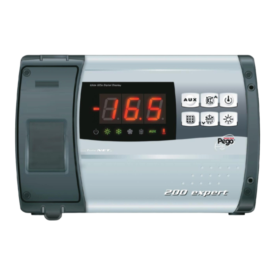
GENERAL DESCRIPTION: The ECP200 EXPERT D7.5 is a new control panel for cold rooms with a single-phase compressor up to 2 HP and three-phase+N electrical defrost up to 7500W (2500W x 3). It allows the user to control all the components on a refrigerating system: compressor, evaporator fans, defrosting elements, room light and thermostat-holder demisting element. -
Page 5: Overall Dimensions
CAP. 1 - Introduction OVERALL DIMENSIONS Dimensions in mm. IDENTIFICATION DATA The unit described in this manual has an ID plate on the side showing all the relevant identification data: • Name of Manufacturer • Code and model of unit electrical board •... -
Page 6: Important Information For The Installer
CAP. 2 - Installation CHAPTER 2: INSTALLATION IMPORTANT INFORMATION FOR THE INSTALLER 1. Install the device in places where the protection rating is observed and try not to damage the box when drilling holes for wire/pipe seats. 2. Do not use multi-polar cables in which there are wires connected to inductive/power loads or signalling wires (e.g. -
Page 7: Installing The Unit
CAP. 2 - Installation INSTALLING THE UNIT Fig. 1: Raise the transparent cover that shields the magneto-thermal cut-out switch and remove the screw cover on the right-hand side. Fig. 2: Undo the 4 fixing screws at the front of the box. Fig. - Page 8 CAP. 2 - Installation Fig. 6: Use the three existing holes to fix the box back panel to the wall: use three screws of a length suitable for the thickness of the wall to which the panel will be attached. Fit a rubber washer (supplied) between...
-
Page 9: Ecp200 Expert D7.5 Panel Functions
CAP. 3 - Functions CHAPTER 3: FUNCTIONS ECP200 EXPERT D7.5 PANEL FUNCTIONS Display and adjustment of cold room temperature accurate to 0.1 °C. Display of evaporator temperature from parameter System control activation/deactivation System warnings (probe/sensor errors, minimum and maximum temperature warnings,... -
Page 10: Technical Characteristics
NTC 10K 1% Resolution 0,1 °C. Sensor read precision ± 0,5 °C -45…+45 °C Read range ECP200 EXPERT D7.5 - Output characteristics - max applicable load (230 V AC) Compressor 1500W (AC3) Single-phase Elements 7500W (2500W 230V x 3) (AC1) Threephase+N... -
Page 11: Warranty
CAP. 4 - Technical characteristics WARRANTY The electronic controllers in the ECP200 EXPERT D7.5 are covered by a 24-month warranty against all manufacturing defects, valid from date of delivery. If the system malfunctions as a result of tampering, impact or improper installation the warranty will automatically be rendered null and void. -
Page 12: Parameter Programming
CAP. 5 - Parameter programming CHAPTER 5: PARAMETER PROGRAMMING CONTROL PANEL FRONT KEYPAD key: AUXILIARY RELAY CONTROL (on the version with alarm relay controls the relay manual if parameter AU=1) key: UP / MUTE WARNING BUZZER key: STAND BY (if the system shuts down the LED flashes) key: room temperature SETTING key: DOWN / MANUAL DEFROST... -
Page 13: Led Display
CAP. 5 - Parameter programming LED DISPLAY 1. Cold room temperature / parameters 2. Stand-by (flashes on stand-by. Outputs are deactivated) 3. Room light (flashes if door switch activated) 4. -
Page 14: General
CAP. 5 - Parameter programming GENERAL To enhance safety and simplify the operator’s work, the ECP200 EXPERT D7.5 has two programming levels; the first level (Level 1) is used to configure the frequently-modified SETPOINT parameters. The second programming level (Level 2) is for general parameter programming of the various controller work modes. -
Page 15: Level 1 Programming
CAP. 5 - Parameter programming LEVEL 1 PROGRAMMING (User level) To gain access to the Level 1 configuration menu proceed as follows: 1. Press the () and () keys simultaneously and keep them pressed for a few seconds until the first programming variable appears on the display. 2. -
Page 16: List Of Level 1 Variables
CAP. 5 - Parameter programming LIST OF LEVEL 1 VARIABLES (User level) VARIABLES MEANING VALUE DEFAULT Temperature difference compared to main SETPOINT 0.2 - 10 °C 2°C Defrost interval (hours) 0 - 24 hours 4 hours End-of-defrost setpoint. Defrost is not executed if the temperature read by the defrost sensor is greater than d2 -35 - 45 °C 15°C... -
Page 17: Level 2 Programming
CAP. 5 - Parameter programming LEVEL 2 PROGRAMMING (Installer level) To access the second programming level press the UP () and DOWN () keys and the LIGHT key simultaneously for a few seconds. When the first programming variable appears the system automatically goes to stand-by. 1. - Page 18 Compressor safety time for door switch: when the door is opened the 0…5 minutes evaporator fans shut down and the compressor will continue working for time doC, after which it will shut down. Compressor restart time after door 0…240 min opening.
-
Page 19: Switching On The Ecp200 Expert D7.5 Electronic Controller
LEDs will come on simultaneously for a few seconds. COMPRESSOR ACTIVATION/DEACTIVATION CONDITIONS 5.12 The ECP200 EXPERT D7.5 controller activates the compressor when cold room temperature exceeds setting+differential (r0); it deactivates the compressor when cold room temperature is lower than the setting. -
Page 20: Hot Gas Defrosting
CAP. 5 - Parameter programming HOT GAS DEFROSTING 5.14 Set parameter d1 =1 to defrost in cycle inversion mode. The compressor relay and defrost relay are activated throughout the defrost phase. To ensure proper control of the system the installer must use the defrost output: this must allow opening of the cycle inversion solenoid valve and closure of the liquid solenoid valve. -
Page 21: Telenet Monitoring/Supervision System
CHAPTER 6: OPTIONAL KITS TeleNET MONITORING/SUPERVISION SYSTEM For connections regarding the TeleNET monitoring/supervision system see APPENDIX A.3 a page 26 of this manual and, for the ECP200 EXPERT D7.5 jumper JP2 as described in 6.2 ON page 22. Rev. 01-16... -
Page 22: Alarm Relay / Telenet Switching
CAP. 6 - Optional kits ALARM RELAY / TeleNET SWITCHING Fig. 1: Open the front of the box as described in Chap. 2.3 (page 7): rotate it downwards 180° to gain access to the electronic board. Fig.2: Undo the 6 CPU board fixing screws: remove the board from the frontal part of the box in ABS. -
Page 23: Troubleshooting
CHAPTER 7: TROUBLESHOOTING TROUBLESHOOTING In the event of any anomalies the ECP200 EXPERT D7.5 warns the operator by displaying alarm codes and sounding the warning buzzer inside the control panel. If an alarm is tripped the display will show one of the following messages:... -
Page 24: Appendices
Appendices APPENDICES EC declaration of conformity COSTRUTTORE / MANUFACTURER: PEGO S.r.l. Via Piacentina, 6/b 45030 Occhiobello (RO) – Italy – Tel. (+39) 0425 762906 Fax. (+39) 0425 762905 DENOMINAZIONE DEL PRODOTTO / NAME OF THE PRODUCT: MOD.: ECP200 EXPERT D7.5 IL PRODOTTO E’... -
Page 25: Ecp200 Expert D7.5 Wiring Diagram
Appendices ECP200 EXPERT D7.5 WIRING DIAGRAM Rev. 01-16 Page 25... -
Page 26: Telenet Network Connection Diagram
Appendices TeleNET NETWORK CONNECTION WIRING DIAGRAM BEFORE CONNECTING UP COMMUTATE THE ALARM RELAY / TELEWIN SWITCHING FUNCTION VIA DIP-SWITCH AS INDICATED CAP. 6.2 USE AND MAINTENANCE MANUAL Page 26 Rev. 01-16... -
Page 27: Part List
Appendices PART LIST REF. DESCRIPTION BOX REAR IN ABS BOX FRONT IN ABS FRONT COVER IN TRANSPARENT POLYCARBONATE BOX FRONT OPENING HINGE BOX CLOSURE SCREWS BOARD FIXING SCREWS DEFROST CONTACTOR CPU BOARD POLYCARBONATE SCREW COVER TERMINAL BLOCK FOR ELECTRICAL PANEL POWER SUPPLY ELECTRICAL BOARD COVER Rev. - Page 28 PEGO S.r.l. Distributor: Via Piacentina, 6/b 45030 OCCHIOBELLO – RO - ITALY Tel : 0425 762906 Fax: 0425 762905 www.pego.it USE AND MAINTENANCE MANUAL Page 28 Rev. 01-16 e-mail: info@pego.it...
Need help?
Do you have a question about the ECP200 Expert d7.5 and is the answer not in the manual?
Questions and answers